EP2808104A1 - Soupape de moulage dotée d'un piston de colmatage - Google Patents
Soupape de moulage dotée d'un piston de colmatage Download PDFInfo
- Publication number
- EP2808104A1 EP2808104A1 EP14167787.2A EP14167787A EP2808104A1 EP 2808104 A1 EP2808104 A1 EP 2808104A1 EP 14167787 A EP14167787 A EP 14167787A EP 2808104 A1 EP2808104 A1 EP 2808104A1
- Authority
- EP
- European Patent Office
- Prior art keywords
- valve
- casting
- piston
- pouring
- melt
- Prior art date
- Legal status (The legal status is an assumption and is not a legal conclusion. Google has not performed a legal analysis and makes no representation as to the accuracy of the status listed.)
- Granted
Links
Images

Classifications
-
- B—PERFORMING OPERATIONS; TRANSPORTING
- B22—CASTING; POWDER METALLURGY
- B22D—CASTING OF METALS; CASTING OF OTHER SUBSTANCES BY THE SAME PROCESSES OR DEVICES
- B22D27/00—Treating the metal in the mould while it is molten or ductile ; Pressure or vacuum casting
- B22D27/09—Treating the metal in the mould while it is molten or ductile ; Pressure or vacuum casting by using pressure
- B22D27/11—Treating the metal in the mould while it is molten or ductile ; Pressure or vacuum casting by using pressure making use of mechanical pressing devices
-
- B—PERFORMING OPERATIONS; TRANSPORTING
- B22—CASTING; POWDER METALLURGY
- B22D—CASTING OF METALS; CASTING OF OTHER SUBSTANCES BY THE SAME PROCESSES OR DEVICES
- B22D17/00—Pressure die casting or injection die casting, i.e. casting in which the metal is forced into a mould under high pressure
- B22D17/20—Accessories: Details
- B22D17/2015—Means for forcing the molten metal into the die
- B22D17/2069—Exerting after-pressure on the moulding material
-
- B—PERFORMING OPERATIONS; TRANSPORTING
- B22—CASTING; POWDER METALLURGY
- B22D—CASTING OF METALS; CASTING OF OTHER SUBSTANCES BY THE SAME PROCESSES OR DEVICES
- B22D17/00—Pressure die casting or injection die casting, i.e. casting in which the metal is forced into a mould under high pressure
- B22D17/20—Accessories: Details
-
- B—PERFORMING OPERATIONS; TRANSPORTING
- B22—CASTING; POWDER METALLURGY
- B22D—CASTING OF METALS; CASTING OF OTHER SUBSTANCES BY THE SAME PROCESSES OR DEVICES
- B22D17/00—Pressure die casting or injection die casting, i.e. casting in which the metal is forced into a mould under high pressure
- B22D17/20—Accessories: Details
- B22D17/2015—Means for forcing the molten metal into the die
-
- B—PERFORMING OPERATIONS; TRANSPORTING
- B22—CASTING; POWDER METALLURGY
- B22D—CASTING OF METALS; CASTING OF OTHER SUBSTANCES BY THE SAME PROCESSES OR DEVICES
- B22D17/00—Pressure die casting or injection die casting, i.e. casting in which the metal is forced into a mould under high pressure
- B22D17/20—Accessories: Details
- B22D17/2015—Means for forcing the molten metal into the die
- B22D17/203—Injection pistons
-
- B—PERFORMING OPERATIONS; TRANSPORTING
- B22—CASTING; POWDER METALLURGY
- B22D—CASTING OF METALS; CASTING OF OTHER SUBSTANCES BY THE SAME PROCESSES OR DEVICES
- B22D17/00—Pressure die casting or injection die casting, i.e. casting in which the metal is forced into a mould under high pressure
- B22D17/20—Accessories: Details
- B22D17/2076—Cutting-off equipment for sprues or ingates
-
- B—PERFORMING OPERATIONS; TRANSPORTING
- B22—CASTING; POWDER METALLURGY
- B22D—CASTING OF METALS; CASTING OF OTHER SUBSTANCES BY THE SAME PROCESSES OR DEVICES
- B22D17/00—Pressure die casting or injection die casting, i.e. casting in which the metal is forced into a mould under high pressure
- B22D17/20—Accessories: Details
- B22D17/30—Accessories for supplying molten metal, e.g. in rations
Definitions
- the invention relates to a pouring valve for supplying melt of a casting device with a valve housing, which has a melt channel connection as inlet and a valve outlet as outlet, with a valve cell for receiving the melt and with a closing means for changing the Ventilauslassqueritess Structure.
- the invention further relates to a casting apparatus with such a casting valve and a casting method for producing castings with this casting apparatus.
- DE 10 2007 047 545 A1 discloses a pouring valve which is closable by means of a piston.
- the piston is axially movable in a valve housing. This gap accuracy due to concentricity errors of the piston does not lead to inhomogeneous mass flows and a reliable closing of the pouring valve is ensured, the piston skirt surface has a larger angle to the valve main axis than the valve housing in the outlet region. In the closed state, the piston thus forms an annular bearing surface with the housing wall.
- Both latter casting valves can be used to reliably fill a casting cavity with a predetermined amount of melt.
- melt must continue to be supplied.
- the above-mentioned pouring valves can not close until the shrinking process has been completed, which requires heating at least until they close and makes precise metering more difficult.
- a second mechanism is required which fills and recompresses the hollow volume resulting from the shrinkage process by means of a melt replenishment.
- the pouring valve and the Nachverdichtungsmechanismus must be coordinated with each other, which is complex, the caster can be built expansively and thus increases the energy required for heating.
- Object of the present invention to improve the prior art and in particular to provide a pouring valve for a casting apparatus, which avoids the disadvantages mentioned above. Furthermore, it is a particular object of the invention to provide a die-casting method for metallic melts, which enables rapid casting while minimizing the supply of heat.
- a pouring valve for supplying melt of a pouring device, wherein the pouring valve comprises a valve housing having a melt channel connection as inlet and a valve outlet as outlet, a valve cell for receiving the melt and a closing means for changing the Ventilauslassqueritess Structure and wherein the valve cell can be connected via a melt channel connection with a melt channel, which can be prestressed by means of casting pressure, and the casting valve has a recompression piston for recompressing the melt after the mold has been filled.
- the integration of the recompression piston as squeeze pin in the pouring valve space-saving arrangement is created, which emits relatively little heat due to their compactness. Due to the fact that the melt for the filling of the casting cavity and the melt for recompression come from the same valve cell or according to the valve outlet downstream of the valve cell, the number of required heating means and pipelines can also be kept low.
- the valve cell of the casting valve can be connected to a melt reservoir or a casting chamber via the melt channel connection. If the pouring valve is part of a die casting device, the melt channel connection, the valve cell and the valve outlet are pressure-resistant.
- the valve cell can also have a plurality of melt channel connections, via which the melt can flow.
- valve cell has a plurality of melt channel connections, it can be provided that the melt flows out again during casting via at least one channel.
- the valve cell thus does not form the end of the melt channel, but is also flowed through by melt during the casting process, which does not leave the pouring valve via the valve outlet.
- the heating means which is arranged in or on the casting valve can be made smaller or possibly omitted entirely.
- the pouring valve may be integrated into the die-cast channel such that the valve cell passes through a part of the melt channel can be prestressed by means of casting pressure.
- the valve cell may have a storage volume, which is advantageously completely enclosed by the valve housing, so that it can be heated as located in the casting valve hot cell. An unwanted solidification can be easily avoided.
- valve cell occupies a certain volume;
- the pouring valve can be integrated in a melt channel particularly well if the cross-sectional area of the valve cell corresponds to the sum of the cross-sectional areas of the feeding melt channel connections. In this case, it is not enlarged in diameter compared to the melt channel and thus provides no additional volume
- the pouring valve preferably has as closing means a valve piston which is movable axially in the direction of the valve outlet and can close it.
- the valve housing and the valve piston are preferably designed so that the diameter of the effective Ventilauslassqueritess founded is steadily reduced when ancestors of the valve piston.
- the effective Ventilauslassqueritess simulation is the surface which is flowed through during the casting vertically from the melt.
- valve piston and the valve piston enclosing housing portion preferably form a conical valve seat.
- At least one of the two components valve piston or housing wall thus has a chamfer or a chamfer in such a way that the Ventilauslassqueritess Structure tapers in the direction of the valve outlet.
- the melt flow can take place through an annular opening which allows a relatively vortex-free melt flow. The effect is exacerbated when both components, the valve piston lateral surface and the housing bottom are seen in the sectional view provided with bevels.
- the bevels do not necessarily have to be conical.
- the housing inner wall or the piston skirt surface may be partially conical or curved in the axial direction. If the piston skirt surface or the valve seat are crowned, concentricity errors of the valve piston can be compensated particularly well, so that despite possible gap dimensions, the mass flow in the closed state is minimized.
- the crown also causes a line contact to form between these components when closing. Jamming of the valve piston can be reliably prevented by the thus lack of surface contact and possibly remaining between the surfaces solidifying melt material, which prevents damage to the valve piston and the valve housing. In the valve gap may have penetrated melt material due to the temperature gradient to the environment cool down and melted at the valve opening for the next casting process again.
- valve piston and the housing wall may be formed in the axial direction specific to the casting so that the tapering valve outlet cross-sectional area formed by the two components is designed so that the desired mold filling speed can be influenced by moving the valve piston.
- a large flow cross-section may be provided, which is required for the rapid filling of the casting cavity and to avoid trapped air, which is reduced with increasing degree of filling according to the shape of the casting cavity.
- the valve piston has a variable diameter over its axial length, with a correspondingly shaped valve housing, only a temporary reduction in the flow cross-section can take place, which is widened again before the final closing of the pouring valve.
- valve piston and the valve outlet are preferably arranged centrally in the valve housing.
- the valve piston drive can connect to the side facing away from the valve outlet and be integrated into the housing of the pouring valve. If the secondary compression piston can be moved via a separate drive, this can also be integrated into the valve housing.
- the melt channel connection In order to prevent a temperature drop of the melt and thus unwanted crystallization processes, can the melt channel connection, the valve outlet or other melt-contacting areas can be made heatable in the pouring valve. Each melting section is preferably heated separately.
- An electrically operated heater has a low inertia behavior and allows good control or regulation of the heating power.
- the channel walls themselves may be heated or covered by coils.
- the valve cell can also be heated.
- the valve piston also takes over the function of Nachverêtns.
- the same component then forms both the closing piston and the Nachverdichtungskolben.
- the valve piston is designed, for example, as a circular cylinder which forms a valve seat with a valve housing wall.
- the valve housing wall can initially be conical and then tubular, so that the valve piston initially throttles the melt flow when moving into the tubular section, closes the valve upon reaching the tubular section, and then recompresses during the process within the tubular section.
- the casting valve on two pistons which are at least temporarily movable relative to each other.
- the first piston is formed by the valve piston, with which the pouring valve is closable, and the second piston is designed as a secondary compression piston separately from the valve piston.
- the two pistons are arranged coaxially with each other, wherein the Nachverdichtungskolben is located inside.
- the housing wall is designed so that the valve piston in this Can move arrangement on the valve wall, is prevented from further movement and due to the smaller diameter of the Nachverdichtungskolbens whose further movement still possible.
- the secondary compression piston may have its own piston drive for the relative movement to the valve piston. As a result, it can be controlled separately from the valve piston, and it can be matched in its performance to the recompression.
- piston actuators for the Nachverdichtungskolben and the valve piston for example, hydraulic drives or electric spindles come into question.
- the two piston drives can also be formed by different drive types.
- a particularly compact pouring valve can be achieved if both pistons are movable by the same drive. Via drive valves or other control mechanisms it can be provided that only one of the pistons or both pistons are displaced simultaneously at a certain point in time. If a relative displacement is undesirable, at least in phases, as in the closing of the pouring valve, both pistons can also be connected to one another by suitable coupling means, so that they can only be moved together.
- the two pistons are coupled to each other and can only be moved to each other by increased effort. As long as the valve piston has not moved to block and thus closes the valve seat on the valve, then move both pistons together. By the then leaps and bounds increasing force dissolves the Nachverdichtungskolben of the valve piston and can then be moved alone. A piston drive is sufficient for this variant. A complex control unit is not required in this embodiment.
- the piston drive is preferably carried out hydraulically and is arranged for thermal reasons on the opposite side of the valve outlet.
- the pouring valve may have the pressure force transmitting decoupling means.
- the decoupling means are disposed between the piston heads and the piston drives and may be formed by ceramic layers or other sufficiently strong thermal insulators.
- the heat transfer can be reduced by a suitable mechanical structure.
- thin-walled intermediate bolts which connect the piston head to the piston drive, transmit less total heat and allow the arrangement of coolants in the spaces thus created.
- the pouring valve according to the invention is preferably installed in a die casting apparatus for metallic melts, but can also be used in other casting methods, such as in continuous casting or casting of non-metallic melts.
- the amount of circulating material is thereby reduces filling and recompression via the same pouring valve.
- a casting device preferably has the pouring valve according to the invention directly on the gate area of the casting or on the casting itself.
- the proportion of Sprue and the amount of circulating material can be further reduced.
- casting compositions of less than 20% of the casting mass can be achieved thereby.
- the sprue system can be compact.
- the sprue material can be reused as circulating material. The fact that less sprue material must be melted and the hot melt in the loop is always close to the mold cavity available, less time for the casting cycle is required, so that the timing is improved.
- the invention also relates to a method for die casting with a die casting device and a valve piston having a casting valve, which provides the following steps: providing a cleaned and prepared for a mold filling casting cavity with a closed pouring valve, opening the pouring valve for pouring, closing the pouring valve after Form Sprintde, removing the Casting and re-compression during the cooling process and before the removal of the casting by means of a built-in the pouring valve piston.
- the proposed method allows the filling and the recompression via the same gate opening, so that the number of gate areas is reduced compared to separately arranged to the casting valve squeeze pins.
- the required post-processing of the casting is thus reduced.
- FIG. 1 schematically shows a part of a casting apparatus 1 for die casting of metallic melts 2 such as magnesium or aluminum melts.
- the casting apparatus 1 has a casting chamber 4, which can be filled from a melt reservoir, not shown, via a melt valve 19.
- the melt 2 is conveyed from the horizontally oriented casting chamber 4 by a hydraulically moved, in the horizontal advancing casting piston 6 in a melt channel 11 and pressurized.
- the melt channel 11 is surrounded by heating means 5 in the form of coils, which prevent cooling of the melt 2. From the heated melt channel 11, the melt 2 passes through a melt channel connection 12 into the valve cell 8 (FIG. FIG. 2 ) of the pouring valve 7 and from there via the valve outlet 10 into the casting cavity 3.
- the casting cavity 3 itself is formed by two half-molds 15, 16 and is formed in a known manner by the enlarged by the Schwindmann negative mold of the casting to be produced.
- the half-molds 15, 16 are separable from each other at a parting surface 9, so that the finished casting can be removed.
- FIG. 2 shows a pouring valve 7 with a valve housing 13 which has a fillable via the melt channel connection 12 valve cell 8, which is part of the melt channel 11 itself and in comparison to this and the melt channel connection 12 has no enlarged cross-section.
- the valve piston 14 Centrally in the valve housing 13, the valve piston 14 is arranged, via which the valve outlet 10 is closed.
- the inner wall 21 of the valve housing 13, which adjoins the Ventilauslass 10 has an inclination relative to the main valve axis 22, which is greater than that of the lateral surface 18.
- valve piston 14 is driven by a first piston drive 24, which operates hydraulically and is arranged axially offset from the valve piston 14. Since the valve piston 14 is in contact with the hot melt 2, decoupling means 26 are provided in the form of intermediate bolts as spacers mechanically and thus thermally decouple the piston drive 24 with the piston plate 28 from the piston head 29 of the valve piston 14, but the pressure force on the Nevertheless, piston head 29 is transferred.
- the valve piston 14 is formed as a hollow cylinder and has co-axial to the direction of a Nachverdichtungskolben 23.
- the recompression piston 23 has a second piston drive 25 which is operable independently of the first piston drive 24. Its hydraulic chambers 30 are connected axially to those of the first piston drive 24.
- the casting cavity 3 is closed so tightly that it withstands the melt pressure of the subsequent die casting process.
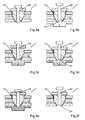
- the inner recompression piston 23 returns to its starting position, which is set back so far from the valve piston 14 closing the valve outlet 10 that a blind hole 27 is created between the inner walls of the valve piston 14.
- the blind hole depth corresponds approximately to the stroke of the valve piston 14th
- valve piston 14 By retracting the valve piston 14, the actual casting process is initiated as a third phase.
- the valve piston 14 releases from its annular valve seat, and by the now flowing, hot melt 2 is possibly at this point cooled material melted. Due to the ring-line contact and any heating located on the pouring valve 7, the solidified amount of melt is so small that it is completely melted and does not make opening the valve piston 14 difficult or only insignificantly difficult.
- the valve outlet 10 is opened to the maximum, and the melt 2 can flow annularly between the pistons 14, 23 and the inner wall 21 of the valve housing 13 in the Gussteilkavmaschine 3. The envisaged for filling amount of melt is pushed by the advancing casting piston 6 via the melt channel 11.
- the casting solidifies and the casting chamber 4 is prepared for a new mold filling operation.
- the consequent shrinkage of material is compensated for by the secondary compression piston 23 which presses the melt 2 located in the blind hole 27 and the immediately adjacent region into the casting cavity. If the amount of melt required for the re-compaction 2 the Blind hole volume corresponds, the adjoining the valve outlet 10 runner can be particularly short or possibly even eliminated.
- the solidification process can be accelerated by supplying cooling power via cooling channels.
Landscapes
- Engineering & Computer Science (AREA)
- Mechanical Engineering (AREA)
- Molds, Cores, And Manufacturing Methods Thereof (AREA)
- Moulds For Moulding Plastics Or The Like (AREA)
- Fuel Cell (AREA)
Applications Claiming Priority (1)
| Application Number | Priority Date | Filing Date | Title |
|---|---|---|---|
| DE102013105435.8A DE102013105435B3 (de) | 2013-05-27 | 2013-05-27 | Gießventil mit einem Nachverdichtungskolben |
Publications (2)
| Publication Number | Publication Date |
|---|---|
| EP2808104A1 true EP2808104A1 (fr) | 2014-12-03 |
| EP2808104B1 EP2808104B1 (fr) | 2016-11-23 |
Family
ID=50679946
Family Applications (1)
| Application Number | Title | Priority Date | Filing Date |
|---|---|---|---|
| EP14167787.2A Active EP2808104B1 (fr) | 2013-05-27 | 2014-05-09 | Soupape de moulage dotée d'un piston de colmatage |
Country Status (5)
| Country | Link |
|---|---|
| US (2) | US9457400B2 (fr) |
| EP (1) | EP2808104B1 (fr) |
| CN (1) | CN104308115B (fr) |
| DE (1) | DE102013105435B3 (fr) |
| ES (1) | ES2609381T3 (fr) |
Cited By (1)
| Publication number | Priority date | Publication date | Assignee | Title |
|---|---|---|---|---|
| DE102020215665A1 (de) | 2020-12-10 | 2022-06-15 | Oskar Frech Gmbh + Co. Kg | Druckgießmaschine mit Absperrventil im Schmelzeeinlasskanal und Betriebsverfahren |
Families Citing this family (8)
| Publication number | Priority date | Publication date | Assignee | Title |
|---|---|---|---|---|
| DE102013105435B3 (de) * | 2013-05-27 | 2014-07-10 | Schuler Pressen Gmbh | Gießventil mit einem Nachverdichtungskolben |
| DE102013105433B3 (de) | 2013-05-27 | 2014-05-22 | Schuler Pressen Gmbh | Gießvorrichtung mit einer Ringleitung und Gießverfahren |
| DE102014205388A1 (de) * | 2014-03-24 | 2015-09-24 | Bayerische Motoren Werke Aktiengesellschaft | Vorrichtung zum Druckgießen eines metallischen Bauteils |
| DE102014111032B3 (de) * | 2014-08-04 | 2015-10-01 | Schuler Pressen Gmbh | Gießventil und Gießvorrichtung |
| JP6455840B2 (ja) * | 2015-09-07 | 2019-01-23 | 株式会社アルテックス | スクイズピン動作判定装置及びスクイズピン動作判定方法 |
| JP7254619B2 (ja) * | 2019-05-17 | 2023-04-10 | 芝浦機械株式会社 | ダイカストマシン |
| JP7556710B2 (ja) * | 2020-06-30 | 2024-09-26 | 株式会社キッツ | バルブのボデーとバルブのボデーの製造方法 |
| CN114030143B (zh) * | 2021-11-17 | 2022-07-22 | 徐州云泰精密技术有限公司 | 一种冲裁集电环水口装置 |
Citations (5)
| Publication number | Priority date | Publication date | Assignee | Title |
|---|---|---|---|---|
| DE3427940A1 (de) | 1984-07-28 | 1986-02-06 | Friedhelm Prof.Dr.-Ing. 6332 Ehringshausen Kahn | Verfahren und vorrichtungen zur steuerung einer raumausfuellung durch metallschmelzen mit hilfe von elektromagnetischen feldern |
| DE19508867A1 (de) * | 1994-06-01 | 1995-12-07 | Buehler Ag | Druckgießmaschine |
| DE19533447C1 (de) * | 1995-09-09 | 1996-12-05 | Bbs Kraftfahrzeugtechnik | Verfahren und Vorrichtung zum Befüllen eines Gießwerkzeugs mit einer Metallschmelze |
| DE102007047545A1 (de) | 2007-09-29 | 2009-04-02 | Eglass Production & Trade Gmbh | Vorrichtung zur Dosierung und zur Zuführung niedrigviskoser Schmelzen |
| DE102011050149A1 (de) | 2010-11-17 | 2012-05-24 | Ferrofacta Gmbh | Druckgussdüse und Druckgussverfahren |
Family Cites Families (13)
| Publication number | Priority date | Publication date | Assignee | Title |
|---|---|---|---|---|
| DE1847509U (de) * | 1961-09-12 | 1962-03-01 | Odenwaelder Kunststoffwerk Dr | Schiebeduese mit nadelverschlub fuer spritzgussmaschinen. |
| US3960201A (en) * | 1974-12-13 | 1976-06-01 | Societe De Vente De L'aluminium Pechiney | Injection device for molding machines |
| JP2504099B2 (ja) * | 1987-02-28 | 1996-06-05 | 日本電装株式会社 | ダイカスト方法およびダイカスト装置 |
| DE3831938A1 (de) * | 1987-09-21 | 1989-04-06 | Ube Industries | Giessvorrichtung |
| JP3477124B2 (ja) * | 1999-10-21 | 2003-12-10 | 株式会社日本製鋼所 | 金属射出成形機における離型剤の塗布方法および金属射出成形用金型 |
| DE10001088A1 (de) * | 2000-01-13 | 2001-07-19 | Bayerische Motoren Werke Ag | Druckgiesswerkzeug |
| DE10305756A1 (de) * | 2003-02-11 | 2004-08-19 | Günther Gmbh & Co., Metallverarbeitung | Verfahren zum Herstellen von Spritzgießartikeln und Nadelverschlußdüse für ein Spritzgießwerkzeug |
| DE20302845U1 (de) * | 2003-02-20 | 2003-05-22 | Günther GmbH & Co., Metallverarbeitung, 35066 Frankenberg | Nadelverschlußdüse |
| EP1524048B1 (fr) * | 2003-10-15 | 2007-02-28 | Fondarex S.A. | Appareil de moulage sous presssion ou par injection |
| DE102006049073A1 (de) * | 2006-10-13 | 2008-04-17 | Hasco Hasenclever Gmbh + Co Kg | Einspritzdüse zur Führung von Schmelzemasse in einer Kunststoffspritzgießform |
| DE102009057197B3 (de) * | 2009-11-30 | 2011-05-19 | Oskar Frech Gmbh + Co. Kg | Gießeinheit für eine Druckgießmaschine |
| JP5120429B2 (ja) * | 2010-08-24 | 2013-01-16 | 株式会社デンソー | 真空ダイカスト装置 |
| DE102013105435B3 (de) * | 2013-05-27 | 2014-07-10 | Schuler Pressen Gmbh | Gießventil mit einem Nachverdichtungskolben |
-
2013
- 2013-05-27 DE DE102013105435.8A patent/DE102013105435B3/de not_active Expired - Fee Related
-
2014
- 2014-04-21 CN CN201410160136.9A patent/CN104308115B/zh not_active Expired - Fee Related
- 2014-05-09 EP EP14167787.2A patent/EP2808104B1/fr active Active
- 2014-05-09 ES ES14167787.2T patent/ES2609381T3/es active Active
- 2014-05-19 US US14/280,679 patent/US9457400B2/en not_active Expired - Fee Related
-
2016
- 2016-01-21 US US15/002,406 patent/US9643245B2/en not_active Expired - Fee Related
Patent Citations (5)
| Publication number | Priority date | Publication date | Assignee | Title |
|---|---|---|---|---|
| DE3427940A1 (de) | 1984-07-28 | 1986-02-06 | Friedhelm Prof.Dr.-Ing. 6332 Ehringshausen Kahn | Verfahren und vorrichtungen zur steuerung einer raumausfuellung durch metallschmelzen mit hilfe von elektromagnetischen feldern |
| DE19508867A1 (de) * | 1994-06-01 | 1995-12-07 | Buehler Ag | Druckgießmaschine |
| DE19533447C1 (de) * | 1995-09-09 | 1996-12-05 | Bbs Kraftfahrzeugtechnik | Verfahren und Vorrichtung zum Befüllen eines Gießwerkzeugs mit einer Metallschmelze |
| DE102007047545A1 (de) | 2007-09-29 | 2009-04-02 | Eglass Production & Trade Gmbh | Vorrichtung zur Dosierung und zur Zuführung niedrigviskoser Schmelzen |
| DE102011050149A1 (de) | 2010-11-17 | 2012-05-24 | Ferrofacta Gmbh | Druckgussdüse und Druckgussverfahren |
Cited By (2)
| Publication number | Priority date | Publication date | Assignee | Title |
|---|---|---|---|---|
| DE102020215665A1 (de) | 2020-12-10 | 2022-06-15 | Oskar Frech Gmbh + Co. Kg | Druckgießmaschine mit Absperrventil im Schmelzeeinlasskanal und Betriebsverfahren |
| US12121961B2 (en) | 2020-12-10 | 2024-10-22 | Oskar Frech Gmbh + Co. Kg | Die-casting machine having a shut-off valve in the melt inlet channel and operating method |
Also Published As
| Publication number | Publication date |
|---|---|
| EP2808104B1 (fr) | 2016-11-23 |
| US9643245B2 (en) | 2017-05-09 |
| CN104308115B (zh) | 2018-11-09 |
| US9457400B2 (en) | 2016-10-04 |
| DE102013105435B3 (de) | 2014-07-10 |
| CN104308115A (zh) | 2015-01-28 |
| ES2609381T3 (es) | 2017-04-20 |
| US20140345824A1 (en) | 2014-11-27 |
| US20160129500A1 (en) | 2016-05-12 |
Similar Documents
| Publication | Publication Date | Title |
|---|---|---|
| EP2808104B1 (fr) | Soupape de moulage dotée d'un piston de colmatage | |
| EP1201335B1 (fr) | Procédé pour la fabrication de pièces coulées sous pression , en particulier à partir de metaux non-ferreux | |
| DE19717381B4 (de) | Spritzgießventil mit Kopf- und Halsbereich | |
| DE69100888T2 (de) | Etagenform mit isoliertem Einspritzkanal. | |
| EP0781640B1 (fr) | Buse obturatrice à aiguille chauffée | |
| DE3926357A1 (de) | Spritzgiesseinrichtung mit einem nadelverschluss | |
| DE2753157A1 (de) | Druckgussmaschine | |
| DE60209505T3 (de) | Verfahren zum spritzgiessen | |
| DE10393767T5 (de) | Spritzgießeinheit in einer Kaltkammer-Druckgussmaschine und darin angewandtes Dosierverfahren | |
| AT512229B1 (de) | Vorrichtung, anlage und verfahren zum druckgiessen von metallischem material im thixotropen zustand | |
| DE4137664B4 (de) | Spritzgießvorrichtung mit gesondertem Heizelement im den Formhohlraum bildenden Einsatz | |
| DE69812502T2 (de) | Giesskammer für eine Druckgiessmaschine und ein Verfahren zum Entfernen von Verunreinigungen | |
| EP2929957A1 (fr) | Machine et procédé de coulée sous pression pour la fabrication de plusieurs pièces de fonderie | |
| EP2145747B1 (fr) | Dispositif et procédé de moulage destinés à la fabrication d'objets creux dotés d'un projectile formé lors du processus de moulage | |
| DE102012203039B4 (de) | Verfahren zum Betreiben einer Druckgussmaschine mit einer Schmelzetransportvorrichtung | |
| DE3780067T2 (de) | Verfahren und vorrichtung zum formen felgenaehnlicher formstuecke. | |
| EP3122494B1 (fr) | Dispositif de coulée sous pression d'une pièce métallique | |
| EP3697554B1 (fr) | Moule de coulée sous pression pour la coulée de carters-cylindres ou de parties inférieures de carters de vilebrequin | |
| EP3523069A1 (fr) | Cloison à insérer dans une lingotière | |
| EP3423215B1 (fr) | Système de buses pour coulée sous pression | |
| EP3771506B1 (fr) | Procédé de coulée au moyen d'un contour de moulage destiné à la fabrication d'un noyau, composant et système de fabrication d'un composant | |
| DE102014111032B3 (de) | Gießventil und Gießvorrichtung | |
| WO2016000006A1 (fr) | Dispositif et procédé pour la réalisation d'au moins une pièce métallique | |
| EP3790689B1 (fr) | Module d'un dispositif de moulage sous pression | |
| EP1713602B1 (fr) | Machine a couler pour produire des pieces coulees en fonte |
Legal Events
| Date | Code | Title | Description |
|---|---|---|---|
| PUAI | Public reference made under article 153(3) epc to a published international application that has entered the european phase |
Free format text: ORIGINAL CODE: 0009012 |
|
| 17P | Request for examination filed |
Effective date: 20140509 |
|
| AK | Designated contracting states |
Kind code of ref document: A1 Designated state(s): AL AT BE BG CH CY CZ DE DK EE ES FI FR GB GR HR HU IE IS IT LI LT LU LV MC MK MT NL NO PL PT RO RS SE SI SK SM TR |
|
| AX | Request for extension of the european patent |
Extension state: BA ME |
|
| R17P | Request for examination filed (corrected) |
Effective date: 20141208 |
|
| RBV | Designated contracting states (corrected) |
Designated state(s): AL AT BE BG CH CY CZ DE DK EE ES FI FR GB GR HR HU IE IS IT LI LT LU LV MC MK MT NL NO PL PT RO RS SE SI SK SM TR |
|
| GRAP | Despatch of communication of intention to grant a patent |
Free format text: ORIGINAL CODE: EPIDOSNIGR1 |
|
| RIC1 | Information provided on ipc code assigned before grant |
Ipc: B22D 27/11 20060101ALI20160603BHEP Ipc: B22D 17/20 20060101AFI20160603BHEP Ipc: B22D 17/30 20060101ALI20160603BHEP |
|
| INTG | Intention to grant announced |
Effective date: 20160622 |
|
| GRAS | Grant fee paid |
Free format text: ORIGINAL CODE: EPIDOSNIGR3 |
|
| GRAA | (expected) grant |
Free format text: ORIGINAL CODE: 0009210 |
|
| AK | Designated contracting states |
Kind code of ref document: B1 Designated state(s): AL AT BE BG CH CY CZ DE DK EE ES FI FR GB GR HR HU IE IS IT LI LT LU LV MC MK MT NL NO PL PT RO RS SE SI SK SM TR |
|
| REG | Reference to a national code |
Ref country code: GB Ref legal event code: FG4D Free format text: NOT ENGLISH |
|
| REG | Reference to a national code |
Ref country code: CH Ref legal event code: EP |
|
| REG | Reference to a national code |
Ref country code: IE Ref legal event code: FG4D Free format text: LANGUAGE OF EP DOCUMENT: GERMAN |
|
| REG | Reference to a national code |
Ref country code: AT Ref legal event code: REF Ref document number: 847407 Country of ref document: AT Kind code of ref document: T Effective date: 20161215 |
|
| REG | Reference to a national code |
Ref country code: DE Ref legal event code: R096 Ref document number: 502014002021 Country of ref document: DE |
|
| REG | Reference to a national code |
Ref country code: DE Ref legal event code: R096 Ref document number: 502014002021 Country of ref document: DE |
|
| PG25 | Lapsed in a contracting state [announced via postgrant information from national office to epo] |
Ref country code: LV Free format text: LAPSE BECAUSE OF FAILURE TO SUBMIT A TRANSLATION OF THE DESCRIPTION OR TO PAY THE FEE WITHIN THE PRESCRIBED TIME-LIMIT Effective date: 20161123 |
|
| REG | Reference to a national code |
Ref country code: LT Ref legal event code: MG4D |
|
| REG | Reference to a national code |
Ref country code: NL Ref legal event code: MP Effective date: 20161123 |
|
| REG | Reference to a national code |
Ref country code: ES Ref legal event code: FG2A Ref document number: 2609381 Country of ref document: ES Kind code of ref document: T3 Effective date: 20170420 |
|
| PG25 | Lapsed in a contracting state [announced via postgrant information from national office to epo] |
Ref country code: SE Free format text: LAPSE BECAUSE OF FAILURE TO SUBMIT A TRANSLATION OF THE DESCRIPTION OR TO PAY THE FEE WITHIN THE PRESCRIBED TIME-LIMIT Effective date: 20161123 Ref country code: GR Free format text: LAPSE BECAUSE OF FAILURE TO SUBMIT A TRANSLATION OF THE DESCRIPTION OR TO PAY THE FEE WITHIN THE PRESCRIBED TIME-LIMIT Effective date: 20170224 Ref country code: LT Free format text: LAPSE BECAUSE OF FAILURE TO SUBMIT A TRANSLATION OF THE DESCRIPTION OR TO PAY THE FEE WITHIN THE PRESCRIBED TIME-LIMIT Effective date: 20161123 Ref country code: NL Free format text: LAPSE BECAUSE OF FAILURE TO SUBMIT A TRANSLATION OF THE DESCRIPTION OR TO PAY THE FEE WITHIN THE PRESCRIBED TIME-LIMIT Effective date: 20161123 Ref country code: NO Free format text: LAPSE BECAUSE OF FAILURE TO SUBMIT A TRANSLATION OF THE DESCRIPTION OR TO PAY THE FEE WITHIN THE PRESCRIBED TIME-LIMIT Effective date: 20170223 |
|
| REG | Reference to a national code |
Ref country code: FR Ref legal event code: PLFP Year of fee payment: 4 |
|
| PG25 | Lapsed in a contracting state [announced via postgrant information from national office to epo] |
Ref country code: PL Free format text: LAPSE BECAUSE OF FAILURE TO SUBMIT A TRANSLATION OF THE DESCRIPTION OR TO PAY THE FEE WITHIN THE PRESCRIBED TIME-LIMIT Effective date: 20161123 Ref country code: PT Free format text: LAPSE BECAUSE OF FAILURE TO SUBMIT A TRANSLATION OF THE DESCRIPTION OR TO PAY THE FEE WITHIN THE PRESCRIBED TIME-LIMIT Effective date: 20170323 Ref country code: FI Free format text: LAPSE BECAUSE OF FAILURE TO SUBMIT A TRANSLATION OF THE DESCRIPTION OR TO PAY THE FEE WITHIN THE PRESCRIBED TIME-LIMIT Effective date: 20161123 Ref country code: HR Free format text: LAPSE BECAUSE OF FAILURE TO SUBMIT A TRANSLATION OF THE DESCRIPTION OR TO PAY THE FEE WITHIN THE PRESCRIBED TIME-LIMIT Effective date: 20161123 Ref country code: RS Free format text: LAPSE BECAUSE OF FAILURE TO SUBMIT A TRANSLATION OF THE DESCRIPTION OR TO PAY THE FEE WITHIN THE PRESCRIBED TIME-LIMIT Effective date: 20161123 |
|
| PG25 | Lapsed in a contracting state [announced via postgrant information from national office to epo] |
Ref country code: EE Free format text: LAPSE BECAUSE OF FAILURE TO SUBMIT A TRANSLATION OF THE DESCRIPTION OR TO PAY THE FEE WITHIN THE PRESCRIBED TIME-LIMIT Effective date: 20161123 Ref country code: SK Free format text: LAPSE BECAUSE OF FAILURE TO SUBMIT A TRANSLATION OF THE DESCRIPTION OR TO PAY THE FEE WITHIN THE PRESCRIBED TIME-LIMIT Effective date: 20161123 Ref country code: DK Free format text: LAPSE BECAUSE OF FAILURE TO SUBMIT A TRANSLATION OF THE DESCRIPTION OR TO PAY THE FEE WITHIN THE PRESCRIBED TIME-LIMIT Effective date: 20161123 Ref country code: RO Free format text: LAPSE BECAUSE OF FAILURE TO SUBMIT A TRANSLATION OF THE DESCRIPTION OR TO PAY THE FEE WITHIN THE PRESCRIBED TIME-LIMIT Effective date: 20161123 Ref country code: CZ Free format text: LAPSE BECAUSE OF FAILURE TO SUBMIT A TRANSLATION OF THE DESCRIPTION OR TO PAY THE FEE WITHIN THE PRESCRIBED TIME-LIMIT Effective date: 20161123 |
|
| REG | Reference to a national code |
Ref country code: DE Ref legal event code: R097 Ref document number: 502014002021 Country of ref document: DE |
|
| PG25 | Lapsed in a contracting state [announced via postgrant information from national office to epo] |
Ref country code: LU Free format text: LAPSE BECAUSE OF NON-PAYMENT OF DUE FEES Effective date: 20170531 Ref country code: BG Free format text: LAPSE BECAUSE OF FAILURE TO SUBMIT A TRANSLATION OF THE DESCRIPTION OR TO PAY THE FEE WITHIN THE PRESCRIBED TIME-LIMIT Effective date: 20170223 Ref country code: SM Free format text: LAPSE BECAUSE OF FAILURE TO SUBMIT A TRANSLATION OF THE DESCRIPTION OR TO PAY THE FEE WITHIN THE PRESCRIBED TIME-LIMIT Effective date: 20161123 |
|
| PLBE | No opposition filed within time limit |
Free format text: ORIGINAL CODE: 0009261 |
|
| STAA | Information on the status of an ep patent application or granted ep patent |
Free format text: STATUS: NO OPPOSITION FILED WITHIN TIME LIMIT |
|
| 26N | No opposition filed |
Effective date: 20170824 |
|
| PG25 | Lapsed in a contracting state [announced via postgrant information from national office to epo] |
Ref country code: SI Free format text: LAPSE BECAUSE OF FAILURE TO SUBMIT A TRANSLATION OF THE DESCRIPTION OR TO PAY THE FEE WITHIN THE PRESCRIBED TIME-LIMIT Effective date: 20161123 |
|
| PG25 | Lapsed in a contracting state [announced via postgrant information from national office to epo] |
Ref country code: MC Free format text: LAPSE BECAUSE OF FAILURE TO SUBMIT A TRANSLATION OF THE DESCRIPTION OR TO PAY THE FEE WITHIN THE PRESCRIBED TIME-LIMIT Effective date: 20161123 |
|
| REG | Reference to a national code |
Ref country code: IE Ref legal event code: MM4A |
|
| PG25 | Lapsed in a contracting state [announced via postgrant information from national office to epo] |
Ref country code: LU Free format text: LAPSE BECAUSE OF NON-PAYMENT OF DUE FEES Effective date: 20170509 |
|
| REG | Reference to a national code |
Ref country code: BE Ref legal event code: MM Effective date: 20170531 |
|
| PG25 | Lapsed in a contracting state [announced via postgrant information from national office to epo] |
Ref country code: IE Free format text: LAPSE BECAUSE OF NON-PAYMENT OF DUE FEES Effective date: 20170509 |
|
| REG | Reference to a national code |
Ref country code: FR Ref legal event code: PLFP Year of fee payment: 5 |
|
| PG25 | Lapsed in a contracting state [announced via postgrant information from national office to epo] |
Ref country code: BE Free format text: LAPSE BECAUSE OF NON-PAYMENT OF DUE FEES Effective date: 20170531 |
|
| PG25 | Lapsed in a contracting state [announced via postgrant information from national office to epo] |
Ref country code: MT Free format text: LAPSE BECAUSE OF FAILURE TO SUBMIT A TRANSLATION OF THE DESCRIPTION OR TO PAY THE FEE WITHIN THE PRESCRIBED TIME-LIMIT Effective date: 20161123 |
|
| GBPC | Gb: european patent ceased through non-payment of renewal fee |
Effective date: 20180509 |
|
| PG25 | Lapsed in a contracting state [announced via postgrant information from national office to epo] |
Ref country code: GB Free format text: LAPSE BECAUSE OF NON-PAYMENT OF DUE FEES Effective date: 20180509 |
|
| PG25 | Lapsed in a contracting state [announced via postgrant information from national office to epo] |
Ref country code: HU Free format text: LAPSE BECAUSE OF FAILURE TO SUBMIT A TRANSLATION OF THE DESCRIPTION OR TO PAY THE FEE WITHIN THE PRESCRIBED TIME-LIMIT; INVALID AB INITIO Effective date: 20140509 |
|
| PG25 | Lapsed in a contracting state [announced via postgrant information from national office to epo] |
Ref country code: CY Free format text: LAPSE BECAUSE OF FAILURE TO SUBMIT A TRANSLATION OF THE DESCRIPTION OR TO PAY THE FEE WITHIN THE PRESCRIBED TIME-LIMIT Effective date: 20161123 |
|
| PG25 | Lapsed in a contracting state [announced via postgrant information from national office to epo] |
Ref country code: MK Free format text: LAPSE BECAUSE OF FAILURE TO SUBMIT A TRANSLATION OF THE DESCRIPTION OR TO PAY THE FEE WITHIN THE PRESCRIBED TIME-LIMIT Effective date: 20161123 |
|
| PG25 | Lapsed in a contracting state [announced via postgrant information from national office to epo] |
Ref country code: TR Free format text: LAPSE BECAUSE OF FAILURE TO SUBMIT A TRANSLATION OF THE DESCRIPTION OR TO PAY THE FEE WITHIN THE PRESCRIBED TIME-LIMIT Effective date: 20161123 |
|
| PG25 | Lapsed in a contracting state [announced via postgrant information from national office to epo] |
Ref country code: AL Free format text: LAPSE BECAUSE OF FAILURE TO SUBMIT A TRANSLATION OF THE DESCRIPTION OR TO PAY THE FEE WITHIN THE PRESCRIBED TIME-LIMIT Effective date: 20161123 Ref country code: IS Free format text: LAPSE BECAUSE OF FAILURE TO SUBMIT A TRANSLATION OF THE DESCRIPTION OR TO PAY THE FEE WITHIN THE PRESCRIBED TIME-LIMIT Effective date: 20170323 |
|
| P01 | Opt-out of the competence of the unified patent court (upc) registered |
Effective date: 20230524 |
|
| PGFP | Annual fee paid to national office [announced via postgrant information from national office to epo] |
Ref country code: IT Payment date: 20230531 Year of fee payment: 10 Ref country code: FR Payment date: 20230517 Year of fee payment: 10 Ref country code: ES Payment date: 20230621 Year of fee payment: 10 Ref country code: DE Payment date: 20230421 Year of fee payment: 10 Ref country code: CH Payment date: 20230605 Year of fee payment: 10 |
|
| PGFP | Annual fee paid to national office [announced via postgrant information from national office to epo] |
Ref country code: AT Payment date: 20230516 Year of fee payment: 10 |
|
| REG | Reference to a national code |
Ref country code: DE Ref legal event code: R119 Ref document number: 502014002021 Country of ref document: DE |
|
| REG | Reference to a national code |
Ref country code: CH Ref legal event code: PL |
|
| REG | Reference to a national code |
Ref country code: AT Ref legal event code: MM01 Ref document number: 847407 Country of ref document: AT Kind code of ref document: T Effective date: 20240509 |
|
| PG25 | Lapsed in a contracting state [announced via postgrant information from national office to epo] |
Ref country code: AT Free format text: LAPSE BECAUSE OF NON-PAYMENT OF DUE FEES Effective date: 20240509 |
|
| PG25 | Lapsed in a contracting state [announced via postgrant information from national office to epo] |
Ref country code: AT Free format text: LAPSE BECAUSE OF NON-PAYMENT OF DUE FEES Effective date: 20240509 Ref country code: CH Free format text: LAPSE BECAUSE OF NON-PAYMENT OF DUE FEES Effective date: 20240531 |
|
| PG25 | Lapsed in a contracting state [announced via postgrant information from national office to epo] |
Ref country code: DE Free format text: LAPSE BECAUSE OF NON-PAYMENT OF DUE FEES Effective date: 20241203 |
|
| PG25 | Lapsed in a contracting state [announced via postgrant information from national office to epo] |
Ref country code: FR Free format text: LAPSE BECAUSE OF NON-PAYMENT OF DUE FEES Effective date: 20240531 |
|
| PG25 | Lapsed in a contracting state [announced via postgrant information from national office to epo] |
Ref country code: IT Free format text: LAPSE BECAUSE OF NON-PAYMENT OF DUE FEES Effective date: 20240509 |
|
| REG | Reference to a national code |
Ref country code: ES Ref legal event code: FD2A Effective date: 20250627 |
|
| PG25 | Lapsed in a contracting state [announced via postgrant information from national office to epo] |
Ref country code: ES Free format text: LAPSE BECAUSE OF NON-PAYMENT OF DUE FEES Effective date: 20240510 |