EP2808184B1 - Doppelanhängerkupplungseinheit für Fahrzeug - Google Patents
Doppelanhängerkupplungseinheit für Fahrzeug Download PDFInfo
- Publication number
- EP2808184B1 EP2808184B1 EP14170316.5A EP14170316A EP2808184B1 EP 2808184 B1 EP2808184 B1 EP 2808184B1 EP 14170316 A EP14170316 A EP 14170316A EP 2808184 B1 EP2808184 B1 EP 2808184B1
- Authority
- EP
- European Patent Office
- Prior art keywords
- flange
- hitch
- hitch assembly
- assembly according
- vehicle
- Prior art date
- Legal status (The legal status is an assumption and is not a legal conclusion. Google has not performed a legal analysis and makes no representation as to the accuracy of the status listed.)
- Active
Links
Images


Classifications
-
- B—PERFORMING OPERATIONS; TRANSPORTING
- B60—VEHICLES IN GENERAL
- B60D—VEHICLE CONNECTIONS
- B60D1/00—Traction couplings; Hitches; Draw-gear; Towing devices
- B60D1/01—Traction couplings or hitches characterised by their type
- B60D1/07—Multi-hitch devices, i.e. comprising several hitches of the same or of a different type; Hitch-adaptors, i.e. for converting hitches from one type to another
-
- B—PERFORMING OPERATIONS; TRANSPORTING
- B60—VEHICLES IN GENERAL
- B60D—VEHICLE CONNECTIONS
- B60D1/00—Traction couplings; Hitches; Draw-gear; Towing devices
- B60D1/01—Traction couplings or hitches characterised by their type
- B60D1/02—Bolt or shackle-type couplings
-
- B—PERFORMING OPERATIONS; TRANSPORTING
- B60—VEHICLES IN GENERAL
- B60D—VEHICLE CONNECTIONS
- B60D1/00—Traction couplings; Hitches; Draw-gear; Towing devices
- B60D1/01—Traction couplings or hitches characterised by their type
- B60D1/06—Ball-and-socket hitches
-
- B—PERFORMING OPERATIONS; TRANSPORTING
- B60—VEHICLES IN GENERAL
- B60D—VEHICLE CONNECTIONS
- B60D1/00—Traction couplings; Hitches; Draw-gear; Towing devices
- B60D1/48—Traction couplings; Hitches; Draw-gear; Towing devices characterised by the mounting
- B60D1/485—Traction couplings; Hitches; Draw-gear; Towing devices characterised by the mounting mounted by means of transversal members attached to the frame of a vehicle
-
- B—PERFORMING OPERATIONS; TRANSPORTING
- B60—VEHICLES IN GENERAL
- B60D—VEHICLE CONNECTIONS
- B60D1/00—Traction couplings; Hitches; Draw-gear; Towing devices
- B60D1/48—Traction couplings; Hitches; Draw-gear; Towing devices characterised by the mounting
- B60D1/52—Traction couplings; Hitches; Draw-gear; Towing devices characterised by the mounting removably mounted
Definitions
- the present invention relates to a dual hitch assembly for a vehicle, in particular a traction motor vehicle.
- the hitch assemblies concerned by the present invention are more particularly the assemblies comprising two distinct coupling modes for towing a towed vehicle so as to be able to couple two different types of trailers.
- the document FR-2,740,079 discloses a horse drawn carriage which has two coupling means of the same type.
- the assembly proposed in this document requires an adaptation of both the towing vehicle and the towed assembly.
- the object of the invention is therefore to provide a hitch assembly offering two different coupling modes at specific mounting heights while having a unique mode of connection with a traction vehicle chassis.
- the invention also aims to provide such a coupling assembly wherein the traction of the trailer is carried out in all cases in the median plane of the vehicle. As a result, there is a braking torque and acceleration torque in the hitch. The latter must be designed to withstand this cyclic torque, including fatigue.
- the document EP-2,596,966 discloses a coupling assembly with first coupling means and second coupling means arranged one above the other.
- the first coupling means and the second coupling means are fixed on a mounting plate and the mounting plate is fixed on a drawbar by means of fixing means comprising two brackets each having a first wing and a second wing, the first wings of the brackets being fixed on two opposite faces of the drawbar and the two second wings defining a plane on which is fixed the mounting plate.
- An object of the present invention is to provide a compact hitch device so as to limit the size of the hitch at the rear of the vehicle to which the hitch device is intended.
- the vertically measured distance (or altitude) between a first coupling means corresponding to a first coupling mode and a second coupling means corresponding to a second coupling mode is preferably reduced.
- the coupling device will preferably further easy to integrate on a vehicle and ergonomic.
- the invention will allow coupling to the choice of a trailer having a standard ball hitch system, or a non-standard hitch coupling system.
- the invention also aims to provide a traction motor vehicle with a hitch assembly that allows to hitch the choice of trailers with different types of hitch.
- a double hitch assembly for a vehicle comprising first hitching means, second hitching means and two brackets each having a first wing and a second wing.
- the first wings are fixed parallel to each other vis-à-vis; the second wings are arranged such that they extend from the corresponding first wing away from the other square and so that the second wings are parallel but offset, and the first coupling means and the second coupling means are each fixed to a second wing of a square.
- This new structure makes it possible, thanks to the offset of the second wings, to no longer have the coupling means one above the other. As a result, the hitching means can be brought together, thus making it possible to produce a compact hitch assembly.
- a hitch assembly according to the invention may further comprise a drawbar.
- the brackets are for example bolted to the drawbar sandwiched between the first two wings of the brackets.
- “Drawbar” means any beam, beam, crosshead type, hitch function, attached to the chassis of the vehicle or making integral part of it.
- the frame may be a frame-type chassis, or mechanically welded, tubular, or chassis-hull type, or more generally any vehicle supporting structure.
- brackets are advantageously fixed on the drawbar with bolts passing through the drawbar vertically from one side to the other. This solution simplifies the assembly of the assembly according to the invention.
- first coupling means and the second coupling means are bolted to the second wings of the brackets.
- At least one bracket has an additional face extending from the first wing parallel to the second wing but in the opposite direction. We can then provide a fixation of this additional face on a drawbar or other in a direction perpendicular to the attachment of the first wings.
- the first wing of said bracket preferably comprises a first edge from which the second wing extends and a second edge opposite to the first edge and from which the additional face extends.
- the bracket then has a Z shape.
- the additional face is in the extension of the second wing. We would then have a T-section of the square, the base of the T being formed by the first wing.
- a preferred embodiment provides for the two brackets of the hitch assembly to have a Z-shape.
- a hitch assembly which has two brackets each having an additional face extending from the first wing parallel to one another. to the second wing but in the opposite direction, the first wing of each bracket having a first edge from which extends the second wing and a second edge opposite the first edge and from which the additional face extends.
- each additional face extends so as to face the second wing of the other bracket against this second wing.
- a fixing between the additional faces and the second wings of the two brackets can then be considered to form a set both rigid and easy to assemble.
- Such a hitch assembly can then provide, to further facilitate mounting, that bolts provide both a fixing of a coupling means on a second wing of a square and a connection between the second wing and the face additional the other square.
- a hitch assembly also comprises a drawbar as mentioned above, it may be provided that it further comprises means for fixing the drawbar, that said fixing means comprise two fastening assemblies each having a mounting flange substantially perpendicular to the drawbar, said mounting flange having on one side means for mounting to a traction motor vehicle frame and, on the other hand, clamping means on the drawbar, and that the clamping means comprises a support plate for receiving the drawbar and a clamping flange bolted to the support plate.
- the first coupling means are for example in the form of a ball coupling and / or the second coupling means are in the form of a clevis hitch.
- the present invention also relates to a traction motor vehicle, characterized in that it comprises a coupling assembly as described above.
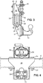
- FIGS. 1 and 2 illustrate at different angles a hitch assembly to be mounted at the rear of a traction vehicle not shown.
- the hitch assembly comprises a drawbar 4, a first part, hereinafter referred to as a top bracket 6, a second part subsequently referred to as the lower bracket 8, a standard ball hitch 14, a clevis hitch 16 as well as means for fixing these various elements.
- the drawbar 4 is formed here of a tubular section section, for example rectangular but other types of profile sections could be used.
- the drawbar 4 is preferably dimensioned to further provide a rear underrun function of the towing vehicle. It can be reported on a chassis of the vehicle or be an integral part of this frame and / or vehicle.
- the drawbar 4 is arranged horizontally, that is to say that its longitudinal axis is horizontal. As illustrated in the drawing, this bar has a rectangular section and it is assumed that this section is oriented so as to have a horizontal upper face, a lower face also horizontal and two vertical side faces connecting the upper face to the lower face.
- the chosen orientation is the "natural" orientation that corresponds to the orientation that is found when the drawbar 4 is mounted on a vehicle. This defines a relative concept up / down which will be used in the following description.
- FIG 5 proposes for example to fix said bar to frame side members.
- a fixing assembly in the illustrated embodiment, comprises a mounting flange 9 formed of an angled plate having at one of its ends frame mounting means which have holes 10 allowing a bolting on a spar 3.
- the figure 5 illustrates in exploded perspective attachment of a cheek 9 externally to a chassis spar.
- the cheek 9 has a welded support plate 11 which is perpendicular thereto and which is pierced with holes 12, thus forming means used to effect a tightening of the drawbar 4.
- the cheek 9 is fastened in parallel at the median plane of the vehicle so that the support plate 11 faces the rear of the vehicle. It is adapted to a recovery interface on the chassis, or an integration interface to it if necessary.
- Each fixing assembly (such as the one illustrated on the figure 5 ) further comprises two flanges 13 U-section bolted in the holes 12 of the corresponding support plate 11 so as to trap and tighten the drawbar 4.
- the latter can be positioned at will perpendicular to the median plane of the vehicle so that the coupling means (ball hitch 14 and clevis hitch 16) are in this median plane, regardless of the spacing of the frame members of the vehicle chassis.
- the fastening flanges 13 may take the form of one or more wire-section stirrups for example.
- the mounting flanges 9 are preferably sized so that the drawbar 4 is positioned to additionally provide the rear underrun function of the towing vehicle.
- the hitching means (ball hitch 14 and clevis hitch 16) are mounted on the hitching bar 4 by mounting means essentially comprising the upper bracket 6 and the lower bracket 8.
- the upper bracket 6 is similar to the lower bracket 8 in the preferred embodiment illustrated in the figures.
- Each bracket has a first wing 18 and a second wing 20. Ribs 21 are provided here between each first wing 18 and the corresponding second wing 20.
- the drawbar 4 is pierced on its horizontal faces with holes 22 for the vertical passage of bolts (screws 24 and nuts 24 '). Holes are also drilled in the first flange 18 of each bracket to fix each bracket by its first flange 18 on the drawbar 4. The first flanges 18 are then arranged horizontally. The screws 24 are long enough to completely cross the drawbar 4 and thus simultaneously ensure the fixing of the two squares on it.
- the brackets are positioned so that the second wings 20 extend vertically and are both parallel.
- the second wing 20 of the upper bracket 6 extends upwardly (thus away from the drawbar 4 and the lower bracket 8) and the second wing 20 of the lower bracket 8 s' extends downwards (thus moving away from the drawbar 4 and the upper bracket 6).
- the second wing 20 of the upper bracket 6 extends in a plane slightly forward of the drawbar 4 while the second wing 20 of the lower bracket 8 is slightly behind the drawbar 4.
- the forward / reverse orientation here corresponds to the orientation of the vehicle on which the drawbar 4 is mounted, the couplings (ball hitch 14 and clevis hitch 16 at the rear of the vehicle).
- Each bracket further comprises an additional face 26 extending in a vertical plane at height including the drawbar 4.
- the additional face 26 of the upper bracket 6 extends from the first flange 18 of this bracket down while the additional face 26 of the lower bracket 8 extends from the first flange 18 of this bracket upwards.
- each bracket thus has a Z-shape which can be obtained by two bends at 90 ° in two opposite directions and around two parallel fold lines, the fold lines corresponding substantially to two edges, so-called edges. longitudinals, the first wing 18.
- Each bracket can thus be obtained by cutting and folding a sheet. A welding operation can also be envisaged to weld the ribs 21.
- each additional face 26 preferably extends sufficiently to be able to face the second flange 20 of the other square and in contact with this second flange 20.
- oblong holes oriented vertically are provided . In the figures, these oblong holes are provided on the additional faces 26 but could also take place on the second wings 20.
- the screws 28 and the associated nuts 28 ' are also used for fixing the hitches.
- the clevis hitch 16 is fixed on the second flange 20 of the upper bracket 6. This second flange 20 is positioned forward with respect to the other second flange 20 (of the lower bracket 8).
- the ball hitch 14 is fixed on the second flange 20 of the lower bracket 8. It is noted here that the additional face 26 of the upper bracket 6 is interposed between the second flange 20 and the ball hitch 14.
- Mounting the hitch assembly on the drawbar 4 is quick and easy to achieve. First of all, fasten the two brackets on the drawbar with screws 24 and nuts 24 '. The brackets are then positioned and you just have to mount the hitches on the second wings of the brackets.
- the couplings are offset, the upper hitch (clevis hitch 16) being shifted forward relative to the lower hitch (ball hitch 14).
- This configuration minimizes the distance measured vertically (or altitude) between the hitches. Indeed, the space above the ball hitch 14 is entirely free and when a trailer comes to tackle this hitch, she is not bothered by the other team. Similarly, the ball hitch 14 does not interfere with the coupling of a trailer on the clevis hitch 16.
- the brackets can also act as reinforcement pieces whose inertia is appropriate according to the needs, in particular as a function of the load to be towed.
- the brackets can be made by folding as mentioned above but also for example by forging.
- a device provides two attachment points for two different coupling modes and this at different specific mounting heights while having a single mode of connection with a chassis of a towing vehicle.
- This provides the advantage for towing vehicles with only one towing beam location to be able to couple two types of trailers optimally (for example standard height "caravan” type hitch and non-standard altitude eye hitch and usually much higher).
- the described device has, on the one hand, a rectangular crossbar (the drawbar) and, secondly, a support that doubles the coupling fixings. These two parts are preferably linked by two bolts passing through the rectangular cross vertically from one side to the other.
- the clamping system with mounting flanges for fixing the drawbar on the vehicle, or more precisely the side rails of a vehicle in the mode described and illustrated, allows to perform continuously all the spacings of "plays "chassis” to fit any width of the towing vehicle frame and can be attached to the inner side or outer side of the side members that constitute the frame of the towing vehicle.
- the latter can fulfill in addition to its support function for the coupling device, the function of rear underrun device for the towing vehicle (height 100 mm, altitude of the lower surface to less than 550 mm from the ground, ends less than 100 mm from the width of the tires).
- the two through bolts determine the mounting position of the hitches so that they are located exactly on the longitudinal median plane of the towing vehicle.
- the device according to the invention has the advantage of allowing attachment by bolting an additional support to provide a fixing to an electrical coupling and a hook for the brake cable of relief, this at different positions to fit the trailer to tow.
- a device according to the invention makes it possible to adapt the relative position of two coupling modes so that it is compatible with the clearance zones required by the coupling standards of each of the coupling modes.
- the invention also makes it possible, by means of a clamping system similar to that of the rectangular crossbar, to simply provide a support for towing vehicle lights, speeding radars, a license plate or additional signage.
Landscapes
- Engineering & Computer Science (AREA)
- Transportation (AREA)
- Mechanical Engineering (AREA)
- Body Structure For Vehicles (AREA)
Claims (12)
- Doppelanhängerkupplungseinheit für ein Fahrzeug, umfassend erste Kupplungsmittel (14), zweite Kupplungsmittel (16) sowie zwei Winkel (6, 8), die jeweils einen ersten Flügel (18) und einen zweiten Flügel (20) aufweisen,
dadurch gekennzeichnet, dass die ersten Flügel (18) parallel zueinander gegenüberliegend befestigt sind,
dass die zweiten Flügel (20) derart angeordnet sind, dass sie sich ausgehend von dem entsprechenden ersten Flügel (18) erstrecken, wobei sie sich von dem anderen Winkel entfernen, und derart, dass die zweiten Flügel (20) parallel, aber versetzt sind, und
dass die ersten Kupplungsmittel (14) und die zweiten Kupplungsmittel (16) jeweils an einem zweiten Flügel (20) eines Winkels befestigt sind. - Anhängerkupplungseinheit nach Anspruch 1, dadurch gekennzeichnet, dass die Winkel (6, 8) mit einer Kupplungsstange (4) verschraubt sind, die sich sandwichartig zwischen den zwei ersten Flügeln der Winkel (6, 8) befindet.
- Anhängerkupplungseinheit nach Anspruch 2, dadurch gekennzeichnet, dass die Winkel (6, 8) an der Kupplungsstange (4) mithilfe von Schrauben (24, 24') befestigt sind, welche die Kupplungsstange (4) vertikal von einer Seite zur anderen durchqueren.
- Anhängerkupplungseinheit nach einem der Ansprüche 1 bis 3, dadurch gekennzeichnet, dass die ersten Kupplungsmittel (14) und die zweiten Kupplungsmittel (16) mit den zweiten Flügeln (20) der Winkel (6, 8) verschraubt sind.
- Anhängerkupplungseinheit nach einem der Ansprüche 1 bis 4, dadurch gekennzeichnet, dass wenigstens ein Winkel (6, 8) eine zusätzliche Fläche (26) aufweist, die sich ausgehend von dem ersten Flügel (18) parallel zum zweiten Flügel (20), aber in entgegengesetzter Richtung, erstreckt.
- Anhängerkupplungseinheit nach Anspruch 5, dadurch gekennzeichnet, dass der erste Flügel (18) des Winkels Folgendes umfasst: einen ersten Rand, von dem aus sich der zweite Flügel (20) erstreckt, sowie einen zweiten Rand, der dem ersten Rand entgegengesetzt ist und von dem aus sich die zusätzliche Fläche (26) erstreckt.
- Anhängerkupplungseinheit nach einem der Ansprüche 1 bis 6, dadurch gekennzeichnet, dass sie zwei Winkel (6, 8) umfasst, die jeweils eine zusätzliche Fläche (26) aufweisen, die sich ausgehend von dem ersten Flügel (18) parallel zum zweiten Flügel (20), aber in entgegengesetzter Richtung, erstreckt, wobei der erste Flügel jedes Winkels (6, 8) Folgendes umfasst: einen ersten Rand, von dem aus sich der zweite Flügel (20) erstreckt, sowie einen zweiten Rand, der dem ersten Rand entgegengesetzt ist und von dem aus sich die zusätzliche Fläche (26) erstreckt, und dass jede zusätzliche Fläche (26) derart verlängert ist, dass sie gegenüber dem zweiten Flügel (20) des anderen Winkels an diesem zweiten Flügel (20) zur Anlage kommt.
- Anhängerkupplungseinheit nach Anspruch 7, dadurch gekennzeichnet, dass Schrauben (28, 28') gleichzeitig eine Befestigung eines Kupplungsmittels an einem zweiten Flügel (20) eines Winkels (6, 8) und eine Verbindung zwischen diesem zweiten Flügel (20) und der zusätzlichen Fläche (26) des anderen Winkels gewährleisten.
- Anhängerkupplungseinheit nach einem der Ansprüche 2 oder 3, dadurch gekennzeichnet, dass sie ferner Mittel zur Befestigung der Kupplungsstange (4) umfasst, dass diese Befestigungsmittel zwei Befestigungseinheiten umfassen, die jeweils eine Montagebacke (9) aufweisen, die im Wesentlichen senkrecht zur Kupplungsstange ist, wobei die Montagebacke auf einer Seite Mittel (10) zur Montage an einem Fahrgestell eines Zugkraftfahrzeugs und auf einer anderen Seite Mittel (11, 13) zum Festklemmen an der Kupplungsstange (4) aufweist, und dass die Festklemmmittel eine Auflageplatte (11) zur Aufnahme der Kupplungsstange (4) und einen mit der Auflageplatte (11) verschraubten Klemmflansch (13) umfassen.
- Anhängerkupplungseinheit nach einem der Ansprüche 1 bis 9, dadurch gekennzeichnet, dass die ersten Kupplungsmittel in Form einer Kugelkupplung (14) vorliegen.
- Anhängerkupplungseinheit nach einem der Ansprüche 1 bis 10, dadurch gekennzeichnet, dass die zweiten Kupplungsmittel in Form einer Fangmaulkupplung (16) vorliegen.
- Zugkraftfahrzeug, dadurch gekennzeichnet, dass es eine Anhängerkupplungseinheit nach einem der vorhergehenden Ansprüche umfasst.
Applications Claiming Priority (1)
| Application Number | Priority Date | Filing Date | Title |
|---|---|---|---|
| FR1354810A FR3006243B1 (fr) | 2013-05-28 | 2013-05-28 | Ensemble d'attelage double pour vehicule |
Publications (2)
| Publication Number | Publication Date |
|---|---|
| EP2808184A1 EP2808184A1 (de) | 2014-12-03 |
| EP2808184B1 true EP2808184B1 (de) | 2018-06-06 |
Family
ID=49209497
Family Applications (1)
| Application Number | Title | Priority Date | Filing Date |
|---|---|---|---|
| EP14170316.5A Active EP2808184B1 (de) | 2013-05-28 | 2014-05-28 | Doppelanhängerkupplungseinheit für Fahrzeug |
Country Status (2)
| Country | Link |
|---|---|
| EP (1) | EP2808184B1 (de) |
| FR (1) | FR3006243B1 (de) |
Families Citing this family (4)
| Publication number | Priority date | Publication date | Assignee | Title |
|---|---|---|---|---|
| DE202015104491U1 (de) | 2015-08-25 | 2016-11-28 | Alois Kober Gmbh | Zugeinrichtung |
| DE102016124562A1 (de) * | 2016-09-30 | 2018-04-05 | Westfalia-Automotive Gmbh | Anhängekupplung mit einem Zuganker |
| DE102021113350A1 (de) | 2021-05-21 | 2022-11-24 | Bayerische Motoren Werke Aktiengesellschaft | Kraftfahrzeug mit einem Federbein |
| FR3152738A1 (fr) * | 2023-09-11 | 2025-03-14 | Renault S.A.S | Agencement pour un attelage de véhicule comprenant un support, une rotule et des moyens de fixation. |
Family Cites Families (5)
| Publication number | Priority date | Publication date | Assignee | Title |
|---|---|---|---|---|
| GB1405499A (en) | 1972-11-08 | 1975-09-10 | Coker K G | Towing hitches |
| NL7901094A (nl) * | 1979-02-12 | 1980-08-14 | Hendrikus Jan Zwaantinus Klein | Koppeling, in het bijzonder voor het verbinden van een trekkend voertuig met een getrokken inrichting. |
| GB2167365A (en) | 1984-11-27 | 1986-05-29 | Kenneth George Coker | A trailer coupling hitch |
| FR2740079B1 (fr) * | 1995-10-23 | 1998-01-16 | Sarl Etablissements Goutorbe & | Dispositif d'attelage entre deux parties roulantes d'un vehicule hippomobile notamment |
| FR2983125B1 (fr) * | 2011-11-25 | 2014-05-02 | Ur Ben | Ensemble d'attelage pour vehicule automobile de traction |
-
2013
- 2013-05-28 FR FR1354810A patent/FR3006243B1/fr not_active Expired - Fee Related
-
2014
- 2014-05-28 EP EP14170316.5A patent/EP2808184B1/de active Active
Non-Patent Citations (1)
| Title |
|---|
| None * |
Also Published As
| Publication number | Publication date |
|---|---|
| FR3006243A1 (fr) | 2014-12-05 |
| EP2808184A1 (de) | 2014-12-03 |
| FR3006243B1 (fr) | 2016-08-26 |
Similar Documents
| Publication | Publication Date | Title |
|---|---|---|
| EP2596966B1 (de) | Anhängerkupplungsanordnung für Zugkraftfahrzeug | |
| FR2922823A1 (fr) | Agencement pour le montage d'un echangeur thermique sur un element de structure vertical formant une face avant technique de vehicule automobile. | |
| FR3090505A1 (fr) | Structure de partie laterale de vehicule | |
| EP2808184A1 (de) | Doppelanhängerkupplungseinheit für Fahrzeug | |
| EP3261860B1 (de) | Anhängesystem | |
| EP2836378B1 (de) | Befestigung einer abschleppvorrichtung mit einem kraftverteilungsträger | |
| EP3459767A1 (de) | Anordnung zur montage eines querträgers an einer kraftfahrzeugkarosserie | |
| FR2474988A1 (fr) | Chassis modulaire, notamment pour les caravanes ou autres remorques routieres | |
| FR2749262A1 (fr) | Chassis de vehicule | |
| EP2424768B1 (de) | Vorrichtung zur befestigung eines motorträgers an einem fahrzeugkarosserieunterbau, verwendung der befestigungsvorrichtung und sich ergebendes fahrzeug | |
| EP3050758B1 (de) | Strukturelle untereinheit eines kraftfahrzeugs, und montageverfahren dieses unterelements | |
| WO2024062165A1 (fr) | Vehicule electrique avec train arrière a traverse déformable et support de déflecteur aérodynamique | |
| FR3140016A1 (fr) | Châssis pour véhicule automobile comprenant des bras de liaison destinés à être solidaires d’une traverse d’attelage | |
| FR3118607A1 (fr) | Dispositif d’attelage à protubérance(s) de pré-maintien, pour un véhicule | |
| FR3141665A1 (fr) | Structure de véhicule automobile avec points de levage | |
| FR3141097A1 (fr) | Système d’attelage de véhicule automobile pourvu de moyens de retenue en cas de choc et à faible encombrement longitudinal | |
| WO2015075333A1 (fr) | Structure de vehicule avec support metallique pour anneau de remorquage de vehicule automobile et vehicule equipes d'une telle structure | |
| EP3119620B1 (de) | System zur kopplung einer reihe von trägern mit einem an der heckstruktur eines kraftfahrzeugs befestigten wirbelhaken | |
| FR3147735A1 (fr) | Pièce de fixation pour fixer une traverse d’attelage à un longeronnet d’un véhicule | |
| EP3686093B1 (de) | Heckstruktur eines kraftfahrzeugs, die mit einer haltestruktur einer ersatzradaufnahmevorrichtung unter dem boden ausgestattet ist | |
| FR3162173A1 (fr) | Ensemble structurel de véhicule comportant un réservoir de carburant et véhicule associé | |
| FR2956064A1 (fr) | Dispositif d'attelage pour vehicule automobile et vehicule equipe d'un tel dispositif d'attelage. | |
| FR3152738A1 (fr) | Agencement pour un attelage de véhicule comprenant un support, une rotule et des moyens de fixation. | |
| EP3152100B1 (de) | Anordnung zum halten eines reservereifens in einem unterboden, kraftfahrzeug mit solch einer anordnung, verfahren zur herstellung derselben und verfahren zur montage einer derartigen anordnung an einem fahrzeug | |
| FR3014809A1 (fr) | Structure de chassis arriere de vehicule a longeronnets relies l'un a l'autre par un support liberable de l'un des longeronnets en cas de choc arriere |
Legal Events
| Date | Code | Title | Description |
|---|---|---|---|
| PUAI | Public reference made under article 153(3) epc to a published international application that has entered the european phase |
Free format text: ORIGINAL CODE: 0009012 |
|
| 17P | Request for examination filed |
Effective date: 20140528 |
|
| AK | Designated contracting states |
Kind code of ref document: A1 Designated state(s): AL AT BE BG CH CY CZ DE DK EE ES FI FR GB GR HR HU IE IS IT LI LT LU LV MC MK MT NL NO PL PT RO RS SE SI SK SM TR |
|
| AX | Request for extension of the european patent |
Extension state: BA ME |
|
| R17P | Request for examination filed (corrected) |
Effective date: 20150529 |
|
| RBV | Designated contracting states (corrected) |
Designated state(s): AL AT BE BG CH CY CZ DE DK EE ES FI FR GB GR HR HU IE IS IT LI LT LU LV MC MK MT NL NO PL PT RO RS SE SI SK SM TR |
|
| GRAP | Despatch of communication of intention to grant a patent |
Free format text: ORIGINAL CODE: EPIDOSNIGR1 |
|
| STAA | Information on the status of an ep patent application or granted ep patent |
Free format text: STATUS: GRANT OF PATENT IS INTENDED |
|
| INTG | Intention to grant announced |
Effective date: 20171122 |
|
| GRAS | Grant fee paid |
Free format text: ORIGINAL CODE: EPIDOSNIGR3 |
|
| GRAJ | Information related to disapproval of communication of intention to grant by the applicant or resumption of examination proceedings by the epo deleted |
Free format text: ORIGINAL CODE: EPIDOSDIGR1 |
|
| GRAL | Information related to payment of fee for publishing/printing deleted |
Free format text: ORIGINAL CODE: EPIDOSDIGR3 |
|
| STAA | Information on the status of an ep patent application or granted ep patent |
Free format text: STATUS: REQUEST FOR EXAMINATION WAS MADE |
|
| RIN1 | Information on inventor provided before grant (corrected) |
Inventor name: FLOTTES, JOEL Inventor name: GAFFARD, BENJAMIN Inventor name: CAVALLARI, PHILIPPE Inventor name: FERAL, JEAN-MARC |
|
| INTC | Intention to grant announced (deleted) | ||
| GRAJ | Information related to disapproval of communication of intention to grant by the applicant or resumption of examination proceedings by the epo deleted |
Free format text: ORIGINAL CODE: EPIDOSDIGR1 |
|
| GRAR | Information related to intention to grant a patent recorded |
Free format text: ORIGINAL CODE: EPIDOSNIGR71 |
|
| STAA | Information on the status of an ep patent application or granted ep patent |
Free format text: STATUS: GRANT OF PATENT IS INTENDED |
|
| GRAA | (expected) grant |
Free format text: ORIGINAL CODE: 0009210 |
|
| STAA | Information on the status of an ep patent application or granted ep patent |
Free format text: STATUS: THE PATENT HAS BEEN GRANTED |
|
| AK | Designated contracting states |
Kind code of ref document: B1 Designated state(s): AL AT BE BG CH CY CZ DE DK EE ES FI FR GB GR HR HU IE IS IT LI LT LU LV MC MK MT NL NO PL PT RO RS SE SI SK SM TR |
|
| INTG | Intention to grant announced |
Effective date: 20180427 |
|
| REG | Reference to a national code |
Ref country code: GB Ref legal event code: FG4D Free format text: NOT ENGLISH |
|
| RIN1 | Information on inventor provided before grant (corrected) |
Inventor name: GAFFARD, BENJAMIN Inventor name: FLOTTES, JOEL Inventor name: FERAL, JEAN-MARC Inventor name: CAVALLARI, PHILIPPE |
|
| REG | Reference to a national code |
Ref country code: CH Ref legal event code: EP Ref country code: AT Ref legal event code: REF Ref document number: 1005667 Country of ref document: AT Kind code of ref document: T Effective date: 20180615 |
|
| REG | Reference to a national code |
Ref country code: IE Ref legal event code: FG4D Free format text: LANGUAGE OF EP DOCUMENT: FRENCH |
|
| REG | Reference to a national code |
Ref country code: DE Ref legal event code: R096 Ref document number: 602014026561 Country of ref document: DE |
|
| REG | Reference to a national code |
Ref country code: NL Ref legal event code: MP Effective date: 20180606 |
|
| REG | Reference to a national code |
Ref country code: LT Ref legal event code: MG4D |
|
| PG25 | Lapsed in a contracting state [announced via postgrant information from national office to epo] |
Ref country code: BG Free format text: LAPSE BECAUSE OF FAILURE TO SUBMIT A TRANSLATION OF THE DESCRIPTION OR TO PAY THE FEE WITHIN THE PRESCRIBED TIME-LIMIT Effective date: 20180906 Ref country code: NO Free format text: LAPSE BECAUSE OF FAILURE TO SUBMIT A TRANSLATION OF THE DESCRIPTION OR TO PAY THE FEE WITHIN THE PRESCRIBED TIME-LIMIT Effective date: 20180906 Ref country code: FI Free format text: LAPSE BECAUSE OF FAILURE TO SUBMIT A TRANSLATION OF THE DESCRIPTION OR TO PAY THE FEE WITHIN THE PRESCRIBED TIME-LIMIT Effective date: 20180606 Ref country code: SE Free format text: LAPSE BECAUSE OF FAILURE TO SUBMIT A TRANSLATION OF THE DESCRIPTION OR TO PAY THE FEE WITHIN THE PRESCRIBED TIME-LIMIT Effective date: 20180606 Ref country code: CY Free format text: LAPSE BECAUSE OF FAILURE TO SUBMIT A TRANSLATION OF THE DESCRIPTION OR TO PAY THE FEE WITHIN THE PRESCRIBED TIME-LIMIT Effective date: 20180606 Ref country code: LT Free format text: LAPSE BECAUSE OF FAILURE TO SUBMIT A TRANSLATION OF THE DESCRIPTION OR TO PAY THE FEE WITHIN THE PRESCRIBED TIME-LIMIT Effective date: 20180606 Ref country code: ES Free format text: LAPSE BECAUSE OF FAILURE TO SUBMIT A TRANSLATION OF THE DESCRIPTION OR TO PAY THE FEE WITHIN THE PRESCRIBED TIME-LIMIT Effective date: 20180606 |
|
| PG25 | Lapsed in a contracting state [announced via postgrant information from national office to epo] |
Ref country code: LV Free format text: LAPSE BECAUSE OF FAILURE TO SUBMIT A TRANSLATION OF THE DESCRIPTION OR TO PAY THE FEE WITHIN THE PRESCRIBED TIME-LIMIT Effective date: 20180606 Ref country code: HR Free format text: LAPSE BECAUSE OF FAILURE TO SUBMIT A TRANSLATION OF THE DESCRIPTION OR TO PAY THE FEE WITHIN THE PRESCRIBED TIME-LIMIT Effective date: 20180606 Ref country code: GR Free format text: LAPSE BECAUSE OF FAILURE TO SUBMIT A TRANSLATION OF THE DESCRIPTION OR TO PAY THE FEE WITHIN THE PRESCRIBED TIME-LIMIT Effective date: 20180907 Ref country code: RS Free format text: LAPSE BECAUSE OF FAILURE TO SUBMIT A TRANSLATION OF THE DESCRIPTION OR TO PAY THE FEE WITHIN THE PRESCRIBED TIME-LIMIT Effective date: 20180606 |
|
| REG | Reference to a national code |
Ref country code: AT Ref legal event code: MK05 Ref document number: 1005667 Country of ref document: AT Kind code of ref document: T Effective date: 20180606 |
|
| PG25 | Lapsed in a contracting state [announced via postgrant information from national office to epo] |
Ref country code: NL Free format text: LAPSE BECAUSE OF FAILURE TO SUBMIT A TRANSLATION OF THE DESCRIPTION OR TO PAY THE FEE WITHIN THE PRESCRIBED TIME-LIMIT Effective date: 20180606 |
|
| PG25 | Lapsed in a contracting state [announced via postgrant information from national office to epo] |
Ref country code: EE Free format text: LAPSE BECAUSE OF FAILURE TO SUBMIT A TRANSLATION OF THE DESCRIPTION OR TO PAY THE FEE WITHIN THE PRESCRIBED TIME-LIMIT Effective date: 20180606 Ref country code: PL Free format text: LAPSE BECAUSE OF FAILURE TO SUBMIT A TRANSLATION OF THE DESCRIPTION OR TO PAY THE FEE WITHIN THE PRESCRIBED TIME-LIMIT Effective date: 20180606 Ref country code: RO Free format text: LAPSE BECAUSE OF FAILURE TO SUBMIT A TRANSLATION OF THE DESCRIPTION OR TO PAY THE FEE WITHIN THE PRESCRIBED TIME-LIMIT Effective date: 20180606 Ref country code: AT Free format text: LAPSE BECAUSE OF FAILURE TO SUBMIT A TRANSLATION OF THE DESCRIPTION OR TO PAY THE FEE WITHIN THE PRESCRIBED TIME-LIMIT Effective date: 20180606 Ref country code: IS Free format text: LAPSE BECAUSE OF FAILURE TO SUBMIT A TRANSLATION OF THE DESCRIPTION OR TO PAY THE FEE WITHIN THE PRESCRIBED TIME-LIMIT Effective date: 20181006 Ref country code: CZ Free format text: LAPSE BECAUSE OF FAILURE TO SUBMIT A TRANSLATION OF THE DESCRIPTION OR TO PAY THE FEE WITHIN THE PRESCRIBED TIME-LIMIT Effective date: 20180606 Ref country code: SK Free format text: LAPSE BECAUSE OF FAILURE TO SUBMIT A TRANSLATION OF THE DESCRIPTION OR TO PAY THE FEE WITHIN THE PRESCRIBED TIME-LIMIT Effective date: 20180606 |
|
| PG25 | Lapsed in a contracting state [announced via postgrant information from national office to epo] |
Ref country code: SM Free format text: LAPSE BECAUSE OF FAILURE TO SUBMIT A TRANSLATION OF THE DESCRIPTION OR TO PAY THE FEE WITHIN THE PRESCRIBED TIME-LIMIT Effective date: 20180606 Ref country code: IT Free format text: LAPSE BECAUSE OF FAILURE TO SUBMIT A TRANSLATION OF THE DESCRIPTION OR TO PAY THE FEE WITHIN THE PRESCRIBED TIME-LIMIT Effective date: 20180606 |
|
| REG | Reference to a national code |
Ref country code: DE Ref legal event code: R097 Ref document number: 602014026561 Country of ref document: DE |
|
| PLBE | No opposition filed within time limit |
Free format text: ORIGINAL CODE: 0009261 |
|
| STAA | Information on the status of an ep patent application or granted ep patent |
Free format text: STATUS: NO OPPOSITION FILED WITHIN TIME LIMIT |
|
| 26N | No opposition filed |
Effective date: 20190307 |
|
| PG25 | Lapsed in a contracting state [announced via postgrant information from national office to epo] |
Ref country code: DK Free format text: LAPSE BECAUSE OF FAILURE TO SUBMIT A TRANSLATION OF THE DESCRIPTION OR TO PAY THE FEE WITHIN THE PRESCRIBED TIME-LIMIT Effective date: 20180606 Ref country code: SI Free format text: LAPSE BECAUSE OF FAILURE TO SUBMIT A TRANSLATION OF THE DESCRIPTION OR TO PAY THE FEE WITHIN THE PRESCRIBED TIME-LIMIT Effective date: 20180606 |
|
| PG25 | Lapsed in a contracting state [announced via postgrant information from national office to epo] |
Ref country code: AL Free format text: LAPSE BECAUSE OF FAILURE TO SUBMIT A TRANSLATION OF THE DESCRIPTION OR TO PAY THE FEE WITHIN THE PRESCRIBED TIME-LIMIT Effective date: 20180606 |
|
| PG25 | Lapsed in a contracting state [announced via postgrant information from national office to epo] |
Ref country code: MC Free format text: LAPSE BECAUSE OF FAILURE TO SUBMIT A TRANSLATION OF THE DESCRIPTION OR TO PAY THE FEE WITHIN THE PRESCRIBED TIME-LIMIT Effective date: 20180606 |
|
| PG25 | Lapsed in a contracting state [announced via postgrant information from national office to epo] |
Ref country code: LU Free format text: LAPSE BECAUSE OF NON-PAYMENT OF DUE FEES Effective date: 20190528 |
|
| PG25 | Lapsed in a contracting state [announced via postgrant information from national office to epo] |
Ref country code: TR Free format text: LAPSE BECAUSE OF FAILURE TO SUBMIT A TRANSLATION OF THE DESCRIPTION OR TO PAY THE FEE WITHIN THE PRESCRIBED TIME-LIMIT Effective date: 20180606 |
|
| PG25 | Lapsed in a contracting state [announced via postgrant information from national office to epo] |
Ref country code: IE Free format text: LAPSE BECAUSE OF NON-PAYMENT OF DUE FEES Effective date: 20190528 |
|
| PG25 | Lapsed in a contracting state [announced via postgrant information from national office to epo] |
Ref country code: PT Free format text: LAPSE BECAUSE OF FAILURE TO SUBMIT A TRANSLATION OF THE DESCRIPTION OR TO PAY THE FEE WITHIN THE PRESCRIBED TIME-LIMIT Effective date: 20181008 |
|
| PG25 | Lapsed in a contracting state [announced via postgrant information from national office to epo] |
Ref country code: MT Free format text: LAPSE BECAUSE OF FAILURE TO SUBMIT A TRANSLATION OF THE DESCRIPTION OR TO PAY THE FEE WITHIN THE PRESCRIBED TIME-LIMIT Effective date: 20180606 Ref country code: HU Free format text: LAPSE BECAUSE OF FAILURE TO SUBMIT A TRANSLATION OF THE DESCRIPTION OR TO PAY THE FEE WITHIN THE PRESCRIBED TIME-LIMIT; INVALID AB INITIO Effective date: 20140528 |
|
| PG25 | Lapsed in a contracting state [announced via postgrant information from national office to epo] |
Ref country code: MK Free format text: LAPSE BECAUSE OF FAILURE TO SUBMIT A TRANSLATION OF THE DESCRIPTION OR TO PAY THE FEE WITHIN THE PRESCRIBED TIME-LIMIT Effective date: 20180606 |
|
| PGFP | Annual fee paid to national office [announced via postgrant information from national office to epo] |
Ref country code: DE Payment date: 20250513 Year of fee payment: 12 |
|
| PGFP | Annual fee paid to national office [announced via postgrant information from national office to epo] |
Ref country code: GB Payment date: 20250521 Year of fee payment: 12 |
|
| PGFP | Annual fee paid to national office [announced via postgrant information from national office to epo] |
Ref country code: BE Payment date: 20250527 Year of fee payment: 12 |
|
| PGFP | Annual fee paid to national office [announced via postgrant information from national office to epo] |
Ref country code: FR Payment date: 20250415 Year of fee payment: 12 |
|
| PGFP | Annual fee paid to national office [announced via postgrant information from national office to epo] |
Ref country code: CH Payment date: 20250601 Year of fee payment: 12 |