EP2808185A1 - Verbesserte Anhängerkupplung und Verfahren zum Anhängen eines Anhängers an ein Fahrzeug - Google Patents
Verbesserte Anhängerkupplung und Verfahren zum Anhängen eines Anhängers an ein Fahrzeug Download PDFInfo
- Publication number
- EP2808185A1 EP2808185A1 EP13169813.6A EP13169813A EP2808185A1 EP 2808185 A1 EP2808185 A1 EP 2808185A1 EP 13169813 A EP13169813 A EP 13169813A EP 2808185 A1 EP2808185 A1 EP 2808185A1
- Authority
- EP
- European Patent Office
- Prior art keywords
- trailer
- link
- tow
- hitch
- connection
- Prior art date
- Legal status (The legal status is an assumption and is not a legal conclusion. Google has not performed a legal analysis and makes no representation as to the accuracy of the status listed.)
- Withdrawn
Links
Images



Classifications
-
- B—PERFORMING OPERATIONS; TRANSPORTING
- B60—VEHICLES IN GENERAL
- B60D—VEHICLE CONNECTIONS
- B60D1/00—Traction couplings; Hitches; Draw-gear; Towing devices
- B60D1/14—Draw-gear or towing devices characterised by their type
- B60D1/173—Draw-gear or towing devices characterised by their type consisting of at least two bars which are not connected or articulated to each other
-
- B—PERFORMING OPERATIONS; TRANSPORTING
- B60—VEHICLES IN GENERAL
- B60D—VEHICLE CONNECTIONS
- B60D1/00—Traction couplings; Hitches; Draw-gear; Towing devices
- B60D1/24—Traction couplings; Hitches; Draw-gear; Towing devices characterised by arrangements for particular functions
- B60D1/30—Traction couplings; Hitches; Draw-gear; Towing devices characterised by arrangements for particular functions for sway control ; Sway alarm means
Definitions
- the present invention relates to an improved trailer coupling and method of hitching a trailer to a tow vehicle, and in particular, to an improved trailer coupling that improves the stability of the tow vehicle and trailer when the trailer coupling is coupled to a tow hitch of the tow vehicle.
- trailer is used to denote a wheeled structure which can be towed behind a vehicle, and is directionally controlled by the direction of travel of the tow vehicle.
- a specific example would be a caravan for instance.
- the tow vehicle has a trailer hitch mounted at the centre of the rear end of the vehicle to which the trailer coupling is attached.
- Typical trailer hitches are towing balls to which a trailer coupling is attached to allow rotation about all three axis of movement. Typically the rotation is referred to as pitch about the sideways axis, roll about the front-to-back axis and yaw about the vertical axis and that terminology is used throughout.
- the invention relates to the operation of a mechanical device built in to a trailer coupling to enhance towing stability, in particular for prevention of oscillation known as snaking.
- the propensity to which this may occur is primarily dependent on speed, the weight and moment of inertia of the trailer, the length of overhand from vehicle back axle to the hitch point and also the weight and suspension stability of the tow vehicle. Applying the vehicle brakes when snaking occurs can exacerbate the condition.
- the effect can be reduced to some extent by adding friction to angular movement at the hitch point. This is commonly achieved either by use of a friction pad of an accessory unit that connects between the vehicle towbar mounting and the trailer chassis, or by application of a strong clamping force on the ball-hitch of the tow vehicle. Although both methods do delay the onset of snaking, it is not prevented at higher speeds or loads, and it can still occur very suddenly without warning.
- Conventional devices to achieve an effective pivot point close to the rear axle do not directly connect a rigid towbar on the trailer to a tow hitch at the rear of the tow vehicle, but use instead two links from tow vehicle to trailer, each pivoted at both ends, and where the distance between the two connection points on the tow vehicle are closer together then the corresponding connections on the trailer.
- This forms a trapezium configuration and creates an effective pivot point at the intersection of the two links. For small angles of turn this causes the trailer to move laterally to keep its centre line approximately aligned with the centre of the rear axle of the tow vehicle, rather than to pivot about the ball hitch point.
- any lateral force applied to the tow vehicle from the trailer will not appreciably affect the direction of travel of the tow vehicle and thus cause snaking to occur.
- These two linkages are normally of identical length and arranged symmetrically either side from the centre line of the trailer.
- a towing system comprises a tow vehicle having a tow hitch and a trailer having a trailer coupling.
- the trailer coupling couples to the tow hitch.
- the trailer coupling has a first link and a second link.
- the first link is coupled to the tow hitch at a centre of the tow vehicle and to the centre of the trailer by first and second respective connections.
- the second link is coupled to the tow hitch and trailer offset from the first link by third and fourth respective connections.
- the first and third connections to the trailer hitch are spaced closer to each other than the second and forth connections to the trailer.
- at least one of the first and second couplings of the first link can be rigid about the pitch axis. This removes the need for complicated arrangements to counteract the downthrust from a nose of the trailer.
- the first or main link connected to the trailer and tow vehicle centrally pivots at the trailer end about a vertical axis only, thus enabling support of any nose weight of the trailer on the main tow-hitch.
- Roll and pitch of the trailer relative to the tow vehicle is achieved via a three-axis joint, such as a ball joint at the tow vehicle.
- the second link or offset link is provided, which is arranged to one side and of greater length than the central link. In the preferred embodiments both ends of this offset link use ball joints so that they can pivot in all directions. By this means any normal rolling movements between tow vehicle and trailer can be accommodated.
- the towing system of the exemplary embodiments achieves the improved stability by creating an effective pivot between the trailer and tow vehicle forward of the actual tow hitch.
- the effective pivot is formed at the intersection of two lines drawn through the first and second connections and the third and fourth connections respectively.
- the effective pivot point can be altered. It has been found that sufficient stability is achieved by arrangeing the effective pivot at or around the rear axle, though in other embodiments, the effective pivot is brought further forwards still and towards the centre of gravity of the tow vehicle. Although this is an asymmetric arrangement the effect for turns of opposite directions is very similar to that of a symmetrical trapezium linkage, and such differences as there are have little effect.
- the centre line of the trailer is offset from the centre line of the tow vehicle such that the assembly acts as if the hitch point is further forward of the actual hitch point, thus achieving the resistance to snaking as required.
- the tow hitch is preferably a standard tow ball. That is, the first connection between the tow hitch and trailer connection takes the form of a standard coupling which decreases complexity and increases ease of use for users used to hitching standard connections.
- the third connection between the offset link and tow hitch may be a second tow ball coupled to the tow vehicle. Alternatively, this second ball hitch can be either directly mounted on the towbar, or be part of a removable arm that can be inserted in the socket fitting of the towbar normally used for attaching a friction type stabiliser.
- the offset link may incorporate means of limiting the force it can apply from tow vehicle to trailer.
- a trailer coupling having a first and second link
- the first link may be centrally mounted or symmetrically mounted about the centre line with the second link
- at least the fourth connection between the second link and trailer is arranged so as to be held fast to the trailer for small angles of turn, that is, whilst the relative angle between the longitudinal centre line of the tow vehicle and the longitudinal centre line of the trailer is between zero and a first angle, and when the relative angle increase above the first angle, the fourth connection is arranged so as to be moveable relative to the trailer.
- this allows the trailer end of the offset linkage to be effectively fixed relative to the trailer during small turning angles, as in this mode the arm to which it is attached is unable to move.
- 4-link couplings as the turn angle further increases the simple trapezium linkage rapidly reaches a critical configuration which limits the maximum permissible turn angle.
- a mechanical system is used to control movement of the trailer end of the offset link by mounting this on an arm which operates in two distinct modes according to the turn angle of the main central link.
- the central link is connected to the trailer at the second connection.
- a third link such as a plate is provided.
- the second, offset link in connected by the fourth connection to the third link.
- the third link is arranged to be selectively coupled fast to either the trailer or the first, central link dependent on the rotation angle between the tow vehicle and trailer.
- the selective coupling is achieved by a selective coupling means.
- the selective coupling means fixes the third link to the trailer until the tow vehicle and trailer form an angle greater than a pre-set angle at which point, the selective coupling means decouples from being held fast to the trailer and is free to rotate about the second connection.
- selective driving means is provided on the first, central link to cause the first link to rotate the third link.
- the selective coupling means comprise followers on the third link.
- the followers abut a plate of the trailer until the angle of rotation exceed the pre-set angle.
- the third link is caused to move laterally relative to the vehicle so that the followers no longer abut the vehicle and allow rotation.
- the selective driving means comprises a follower that cooperates with a slot between the third link and first link.
- the follower and slot are shaped so that the follower can move within the slot whilst the angle between the tow vehicle and trailer is below the pre-set angle.
- the follower abuts the channel so that third link is caused to move relative to the trailer, which releases the selective coupling means.
- Further rotation of the first link cause rotation of the third link by abutment between the follower and slot of the selective driving means.
- the whole mechanical assembly can be mounted on the trailer in a manner that permits some longitudinal movement, and this movement used to operate the trailer brakes.
- At least one of the first to fourth connections is preferably a coupling so that the trailer part and the tow vehicle part can be decoupled to decouple the trailer from the tow vehicle.
- at least the second and fourth connections are permanent joints that are not designed to be readily decoupled during normal use.
- the first connection is a coupling designed to be readily decoupled in use.
- the third connection may be either a coupling or a joint designed to be readily decoupled or relatively permanent respectively during use. When the third connection is a joint, the connection should be otherwise detachable from the tow vehicle.
- a hitch assembly comprising a tow hitch and trailer coupling for retrospective attachment to a tow vehicle and trailer is also envisaged, as is a trailer coupling suitable for coupling to a tow hitch.
- a tow hitch for coupling to a trailer coupling is equally envisaged where these parts are sold, manufactured or imported separately.
- a towing system 10 comprising a tow vehicle 12 having a tow hitch 200 and a trailer 14 having a trailer coupling 100.
- the trailer 14 and tow vehicle 10 are standard and can have any known form. A detailed description is not thought necessary, but the tow vehicle generally has four wheels that support a chassis having a rear end to which the tow hitch can be coupled.
- the trailer has a set of wheels that support a chassis having a front end to which the trailer coupling 100 is attached.
- the trailer coupling 100 couples to the tow hitch 200 so that the trailer is pulled by the tow vehicle via the coupling of the tow hitch 200 and trailer coupling 100.
- the trailer coupling 100 has a first link 110 and a second link 120.
- the first link 110 is coupled to the tow hitch 200 at a centre of the tow vehicle 12 and to the centre of the trailer 14 by first 112 and second 114 respective connections.
- the second link 120 is coupled to the tow hitch 100 and trailer 14 offset from the first link 110 by third 122 and fourth 114 respective connections.
- the first 112 and third 122 connections to the trailer hitch 200 are spaced closer to each other than the second 114 and forth 124 connections to the trailer 14.
- at least one of the first 112 and second 114 couplings of the first link 100 can be rigid about the pitch axis.
- each of the four connections must provide the full three-axis range of movement to accommodate different pitch, roll, and yaw of the tow vehicle to the trailer. This requires an additional means to prevent the nose of the trailer from dropping under gravity.
- the need for this additional means is eliminated by making one of the first 112 and second 114 links rigid in the pitch axis of the trailer.
- the first, third, and fourth connections 112, 122, and 124 have 3-axis range of rotation and are, for example ball joints.
- this allows a standard, central ball hitch to be used as the first connection 112.
- the tow hitch 200 comprises a ball hitch 212 attached to the chassis of the vehicle 12.
- the third connection 122 is also shown as a ball joint and can be attached to the standard ball hitch 212, for example by connecting an arm from the stabiliser connection of the ball hitch 212, wherein said arm has a second ball hitch 222 attached thereto.
- the first and second links 110, 120 connect to the ball hitches 112, 122 in any well known manner and again, for brevity a description is omitted here.
- the second connection 114 includes a mechanism 300 that selectively couples the fourth connection to the trailer. That is, at relatively small turn angles between the tow vehicle and trailer, the fourth connection 122 is held fast to the trailer so its relative position is fixed to the trailer. However, as the angle of turn exceeds a preset angle, the fourth connection 122 is released from the fixed arrangement with the trailer and rotated about a yaw axis of the second connection 112.
- the configuration of the connections in terms of there relative locations are held constant, which allows steeper turn angles without the linkages jamming on each other.
- the mechanism 300 is shown.
- the first link 110 terminates at a plate 116.
- the plate 116 is arranged to rotate about a yaw axis Y.
- Fixed to the vehicle is a fixed plate 310.
- the plate 116 is arranged to rotate relative to the fixed plate, for instance by a rotation pin 312.
- An intermediate plate 320 is arranged between the first plate 116 and the fixed plate 310 wherein the pin 312 passes through the intermediate plate.
- the intermediate plate 320 includes a ball connection 322 for connecting to the second, offset link to form the fourth connection 122.
- the plate 320 forms an arm or third link between the second and fourth connections.
- the fixed plate includes a flat side.
- the intermediate plate includes two followers 324, 326 that in a small turn angle arrangement sit against the flat side of the fixed plate to prevent rotation about the pin 312.
- the first plate 116 selectively couples to the intermediate plate to cause the intermediate plate to shift laterally in a forward or aft direction to release one of the followers from engagement with the flat side of the fixed plate. At this point, the followers do not prevent rotation of the intermediate plate.
- the intermediate plate includes a slot within which the rotation pin 312 is located, said slot accommodating the lateral movement.
- the first plate is selectively coupled to the intermediate plate by abutment between a follower 328 and groove 118.
- the follower is shown on the intermediate plate and the groove on first plate. However, it will be appreciated that this configuration could be swapped.
- the groove allows the follower to freely move as the first plate pivots about said preset small angle relative to the trailer, wherein the follower is fixed fast to the trailer by means of the intermediate plate being held fast to the trailer.
- the groove restrains movement of the follower relative to the first plate. This restrainment causes the intermediate plate to shift forward or aft. It will be appreciated that this shifting releases the intermediate plate from being held fast to the fixed plate.
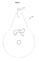
- first plate 116, intermediate plate 320 and fixed plate 310 are shown in Figures 5 , 6 and 7 respectively.
- the mechanism 300 allows free movement of plate 116, the main link to the centre hitch, around the vertical axis Y in the centre of the mechanism.
- the offset link 120 is also free to move around its mounting point 124 on the trailer, a simple trapezium configuration is created, such that a turn to the left, as illustrated in Fig 1 , causes the centre line of the trailer 14 to move left of the main tow-hitch 212, and align approximately with a point on the tow vehicle 10 well forward of this.
- any lateral forces applied by the trailer to the tow vehicle do not substantially affect the direction of travel of the tow vehicle.
- the central section of the groove in the first plate 116 of Figs 4 and 5 follows a radius of the centre pin, so that as plate 116, which is fixed to the first link, is turned small angles either way, intermediate plate 320 of Fig 6 is kept in a position halfway between its most forward and most rearward positions, so cannot pivot because of the two followers touching the fixed plate 310 shown in Fig 7 remain in close contact with the straight section of this fixed plate.
- the turn angle of plate 116 reaches a point where the follower 328 of plate 320 reaches the end of the groove in plate 116. Because the first plate 116 cannot rotate further, increased turning of the tow vehicle causes the offset link to apply a force to the end of the arm and move the entire intermediate plate 320 forwards or rearwards as appropriate. If the three followers are alternatively attached to the intermediate plate 320 on a separate assembly then the movement of this assembly is arranged to allow just the followers to move as required, but plate 320 to stay on a fixed centre.
- intermediate plate 320 enters the appropriate angled end of the groove of plate 116 thus effectively locking together plates 116 and 320, and one of the two followers 324, 326 leaves the straight section of the perimeter of the fixed plate.
- the intermediate plate 320 can now turn only in the same direction of turn as the tow vehicle, and so the assembly of plates 116 and 320 rotate in this direction locked together, enabling the tow vehicle to move to a ninety degree angle relative to the trailer. As the turn is reduced the sequence of operation is reversed, and similar operation is produced for turns in the opposite direction.
- connection 112, 114, 122, 124 can be re-arranged to suit the application. Particularly to place the effective pivot axis as far forward as required.
- cam surfaces or slotted guides are shown as simple single rollers, but these can be double rollers incorporating arrangements to avoid backlash.
- pivot points are shown as simple plain bearings and the plates are shown to contact each other directly, but ball bearing arrangements could be used to reduce friction and durability at these points.
Landscapes
- Engineering & Computer Science (AREA)
- Transportation (AREA)
- Mechanical Engineering (AREA)
- Vehicle Body Suspensions (AREA)
Priority Applications (1)
| Application Number | Priority Date | Filing Date | Title |
|---|---|---|---|
| EP13169813.6A EP2808185A1 (de) | 2013-05-29 | 2013-05-29 | Verbesserte Anhängerkupplung und Verfahren zum Anhängen eines Anhängers an ein Fahrzeug |
Applications Claiming Priority (1)
| Application Number | Priority Date | Filing Date | Title |
|---|---|---|---|
| EP13169813.6A EP2808185A1 (de) | 2013-05-29 | 2013-05-29 | Verbesserte Anhängerkupplung und Verfahren zum Anhängen eines Anhängers an ein Fahrzeug |
Publications (1)
| Publication Number | Publication Date |
|---|---|
| EP2808185A1 true EP2808185A1 (de) | 2014-12-03 |
Family
ID=48534259
Family Applications (1)
| Application Number | Title | Priority Date | Filing Date |
|---|---|---|---|
| EP13169813.6A Withdrawn EP2808185A1 (de) | 2013-05-29 | 2013-05-29 | Verbesserte Anhängerkupplung und Verfahren zum Anhängen eines Anhängers an ein Fahrzeug |
Country Status (1)
| Country | Link |
|---|---|
| EP (1) | EP2808185A1 (de) |
Citations (3)
| Publication number | Priority date | Publication date | Assignee | Title |
|---|---|---|---|---|
| DE3149700A1 (de) * | 1980-12-19 | 1982-07-29 | Alois Kober KG, 8871 Kötz | "kupplungsverbindung zwischen einem zugfahrzeug und einem anhaenger, vorzugsweise einachsanhaenger" |
| US4949987A (en) * | 1982-09-30 | 1990-08-21 | Gallatin Norman W | Asymmetrical four-bar trailer hitch |
| US6485046B1 (en) * | 2001-10-15 | 2002-11-26 | Paul Hsueh | Anti-sway trailer hitch |
-
2013
- 2013-05-29 EP EP13169813.6A patent/EP2808185A1/de not_active Withdrawn
Patent Citations (3)
| Publication number | Priority date | Publication date | Assignee | Title |
|---|---|---|---|---|
| DE3149700A1 (de) * | 1980-12-19 | 1982-07-29 | Alois Kober KG, 8871 Kötz | "kupplungsverbindung zwischen einem zugfahrzeug und einem anhaenger, vorzugsweise einachsanhaenger" |
| US4949987A (en) * | 1982-09-30 | 1990-08-21 | Gallatin Norman W | Asymmetrical four-bar trailer hitch |
| US6485046B1 (en) * | 2001-10-15 | 2002-11-26 | Paul Hsueh | Anti-sway trailer hitch |
Similar Documents
| Publication | Publication Date | Title |
|---|---|---|
| US3955831A (en) | Compound trailer hitch with gooseneck support | |
| US4722542A (en) | Trailer hitch assembly | |
| US4019754A (en) | Vehicle connecting device | |
| US9004519B1 (en) | Tow bar controlled trailer and method | |
| US3194584A (en) | Load transferring trailer hitch | |
| US5520404A (en) | Trailer hitch | |
| US7506886B2 (en) | Slidable fifth-wheel hitch | |
| US4281847A (en) | Trailer hitch | |
| US5382041A (en) | Method and apparatus for connecting a trailer with a rigid drawbar and at least one centrally positioned axle to a tow vehicle | |
| US20240336096A1 (en) | Trailer towing apparatus | |
| KR101937596B1 (ko) | 트레일러 주행 시스템 | |
| US7959179B1 (en) | Tow bar having lunette ring head and fishtail-reducing cammed equiangularly-oriented tow bar legs | |
| US7422226B2 (en) | Anti-sway trailer hitch | |
| US3430975A (en) | Trailer steering arrangement | |
| EP2808185A1 (de) | Verbesserte Anhängerkupplung und Verfahren zum Anhängen eines Anhängers an ein Fahrzeug | |
| EP1215105B1 (de) | Zugeinrichtung für einen Anhänger | |
| US4598926A (en) | Asymmetrical four-bar link trailer hitch | |
| US5320376A (en) | Trailer | |
| US8033561B2 (en) | Sway control device for trailers | |
| US20140151978A1 (en) | Reactive Steering, Instant Center, Twin Linkage System For Use With Tag Trailers For Improved Towability And Safety | |
| US9987965B2 (en) | Safety device for towing trailer | |
| GB2496842A (en) | A linkage for a trailer stabilizing system | |
| EP1368222B1 (de) | Gelenkfahrzeug | |
| US7425011B2 (en) | Trailer hitch | |
| US4191394A (en) | Trailer hitch |
Legal Events
| Date | Code | Title | Description |
|---|---|---|---|
| PUAI | Public reference made under article 153(3) epc to a published international application that has entered the european phase |
Free format text: ORIGINAL CODE: 0009012 |
|
| 17P | Request for examination filed |
Effective date: 20130529 |
|
| AK | Designated contracting states |
Kind code of ref document: A1 Designated state(s): AL AT BE BG CH CY CZ DE DK EE ES FI FR GB GR HR HU IE IS IT LI LT LU LV MC MK MT NL NO PL PT RO RS SE SI SK SM TR |
|
| AX | Request for extension of the european patent |
Extension state: BA ME |
|
| STAA | Information on the status of an ep patent application or granted ep patent |
Free format text: STATUS: THE APPLICATION IS DEEMED TO BE WITHDRAWN |
|
| 18D | Application deemed to be withdrawn |
Effective date: 20150604 |