EP2808196A1 - Elément de transmission - Google Patents
Elément de transmission Download PDFInfo
- Publication number
- EP2808196A1 EP2808196A1 EP13169731.0A EP13169731A EP2808196A1 EP 2808196 A1 EP2808196 A1 EP 2808196A1 EP 13169731 A EP13169731 A EP 13169731A EP 2808196 A1 EP2808196 A1 EP 2808196A1
- Authority
- EP
- European Patent Office
- Prior art keywords
- housing
- transformer element
- secondary part
- electronics
- element according
- Prior art date
- Legal status (The legal status is an assumption and is not a legal conclusion. Google has not performed a legal analysis and makes no representation as to the accuracy of the status listed.)
- Withdrawn
Links
Images
Classifications
-
- H—ELECTRICITY
- H01—ELECTRIC ELEMENTS
- H01F—MAGNETS; INDUCTANCES; TRANSFORMERS; SELECTION OF MATERIALS FOR THEIR MAGNETIC PROPERTIES
- H01F38/00—Adaptations of transformers or inductances for specific applications or functions
- H01F38/14—Inductive couplings
-
- B—PERFORMING OPERATIONS; TRANSPORTING
- B60—VEHICLES IN GENERAL
- B60L—PROPULSION OF ELECTRICALLY-PROPELLED VEHICLES; SUPPLYING ELECTRIC POWER FOR AUXILIARY EQUIPMENT OF ELECTRICALLY-PROPELLED VEHICLES; ELECTRODYNAMIC BRAKE SYSTEMS FOR VEHICLES IN GENERAL; MAGNETIC SUSPENSION OR LEVITATION FOR VEHICLES; MONITORING OPERATING VARIABLES OF ELECTRICALLY-PROPELLED VEHICLES; ELECTRIC SAFETY DEVICES FOR ELECTRICALLY-PROPELLED VEHICLES
- B60L53/00—Methods of charging batteries, specially adapted for electric vehicles; Charging stations or on-board charging equipment therefor; Exchange of energy storage elements in electric vehicles
- B60L53/10—Methods of charging batteries, specially adapted for electric vehicles; Charging stations or on-board charging equipment therefor; Exchange of energy storage elements in electric vehicles characterised by the energy transfer between the charging station and the vehicle
- B60L53/12—Inductive energy transfer
- B60L53/126—Methods for pairing a vehicle and a charging station, e.g. establishing a one-to-one relation between a wireless power transmitter and a wireless power receiver
-
- H—ELECTRICITY
- H01—ELECTRIC ELEMENTS
- H01F—MAGNETS; INDUCTANCES; TRANSFORMERS; SELECTION OF MATERIALS FOR THEIR MAGNETIC PROPERTIES
- H01F27/00—Details of transformers or inductances, in general
- H01F27/02—Casings
-
- H—ELECTRICITY
- H01—ELECTRIC ELEMENTS
- H01F—MAGNETS; INDUCTANCES; TRANSFORMERS; SELECTION OF MATERIALS FOR THEIR MAGNETIC PROPERTIES
- H01F27/00—Details of transformers or inductances, in general
- H01F27/34—Special means for preventing or reducing unwanted electric or magnetic effects, e.g. no-load losses, reactive currents, harmonics, oscillations, leakage fields
- H01F27/36—Electric or magnetic shields or screens
-
- H—ELECTRICITY
- H01—ELECTRIC ELEMENTS
- H01F—MAGNETS; INDUCTANCES; TRANSFORMERS; SELECTION OF MATERIALS FOR THEIR MAGNETIC PROPERTIES
- H01F27/00—Details of transformers or inductances, in general
- H01F27/34—Special means for preventing or reducing unwanted electric or magnetic effects, e.g. no-load losses, reactive currents, harmonics, oscillations, leakage fields
- H01F27/36—Electric or magnetic shields or screens
- H01F27/366—Electric or magnetic shields or screens made of ferromagnetic material
-
- H—ELECTRICITY
- H02—GENERATION; CONVERSION OR DISTRIBUTION OF ELECTRIC POWER
- H02J—ELECTRIC POWER NETWORKS; CIRCUIT ARRANGEMENTS OR SYSTEMS FOR SUPPLYING OR DISTRIBUTING ELECTRIC POWER; SYSTEMS FOR STORING ELECTRIC ENERGY
- H02J50/00—Circuit arrangements or systems for wireless supply or distribution of electric power
- H02J50/10—Circuit arrangements or systems for wireless supply or distribution of electric power using inductive coupling
-
- H—ELECTRICITY
- H02—GENERATION; CONVERSION OR DISTRIBUTION OF ELECTRIC POWER
- H02J—ELECTRIC POWER NETWORKS; CIRCUIT ARRANGEMENTS OR SYSTEMS FOR SUPPLYING OR DISTRIBUTING ELECTRIC POWER; SYSTEMS FOR STORING ELECTRIC ENERGY
- H02J50/00—Circuit arrangements or systems for wireless supply or distribution of electric power
- H02J50/005—Mechanical details of housing or structure aiming to accommodate the power transfer means, e.g. mechanical integration of coils, antennas or transducers into emitting or receiving devices
-
- H—ELECTRICITY
- H02—GENERATION; CONVERSION OR DISTRIBUTION OF ELECTRIC POWER
- H02J—ELECTRIC POWER NETWORKS; CIRCUIT ARRANGEMENTS OR SYSTEMS FOR SUPPLYING OR DISTRIBUTING ELECTRIC POWER; SYSTEMS FOR STORING ELECTRIC ENERGY
- H02J50/00—Circuit arrangements or systems for wireless supply or distribution of electric power
- H02J50/70—Circuit arrangements or systems for wireless supply or distribution of electric power involving the reduction of electric, magnetic or electromagnetic leakage fields
-
- Y—GENERAL TAGGING OF NEW TECHNOLOGICAL DEVELOPMENTS; GENERAL TAGGING OF CROSS-SECTIONAL TECHNOLOGIES SPANNING OVER SEVERAL SECTIONS OF THE IPC; TECHNICAL SUBJECTS COVERED BY FORMER USPC CROSS-REFERENCE ART COLLECTIONS [XRACs] AND DIGESTS
- Y02—TECHNOLOGIES OR APPLICATIONS FOR MITIGATION OR ADAPTATION AGAINST CLIMATE CHANGE
- Y02T—CLIMATE CHANGE MITIGATION TECHNOLOGIES RELATED TO TRANSPORTATION
- Y02T10/00—Road transport of goods or passengers
- Y02T10/60—Other road transportation technologies with climate change mitigation effect
- Y02T10/70—Energy storage systems for electromobility, e.g. batteries
-
- Y—GENERAL TAGGING OF NEW TECHNOLOGICAL DEVELOPMENTS; GENERAL TAGGING OF CROSS-SECTIONAL TECHNOLOGIES SPANNING OVER SEVERAL SECTIONS OF THE IPC; TECHNICAL SUBJECTS COVERED BY FORMER USPC CROSS-REFERENCE ART COLLECTIONS [XRACs] AND DIGESTS
- Y02—TECHNOLOGIES OR APPLICATIONS FOR MITIGATION OR ADAPTATION AGAINST CLIMATE CHANGE
- Y02T—CLIMATE CHANGE MITIGATION TECHNOLOGIES RELATED TO TRANSPORTATION
- Y02T10/00—Road transport of goods or passengers
- Y02T10/60—Other road transportation technologies with climate change mitigation effect
- Y02T10/7072—Electromobility specific charging systems or methods for batteries, ultracapacitors, supercapacitors or double-layer capacitors
-
- Y—GENERAL TAGGING OF NEW TECHNOLOGICAL DEVELOPMENTS; GENERAL TAGGING OF CROSS-SECTIONAL TECHNOLOGIES SPANNING OVER SEVERAL SECTIONS OF THE IPC; TECHNICAL SUBJECTS COVERED BY FORMER USPC CROSS-REFERENCE ART COLLECTIONS [XRACs] AND DIGESTS
- Y02—TECHNOLOGIES OR APPLICATIONS FOR MITIGATION OR ADAPTATION AGAINST CLIMATE CHANGE
- Y02T—CLIMATE CHANGE MITIGATION TECHNOLOGIES RELATED TO TRANSPORTATION
- Y02T90/00—Enabling technologies or technologies with a potential or indirect contribution to GHG emissions mitigation
- Y02T90/10—Technologies relating to charging of electric vehicles
- Y02T90/14—Plug-in electric vehicles
Definitions
- the invention relates to a transformer element for a system for contactless energy transmission between at least one primary part and at least one secondary part, according to the preamble of claim 1, as well as a system for contactless energy transmission and a vehicle with such a system.
- an electronic device in particular a transformer head for supplying the drive of an at least partially electrically operated vehicle based on inductive energy transmission.
- This device has a housing with a secondary winding and an integrated rectifier inside. The secondary winding feeds the rectifier, which is electrically connected to the secondary winding and supplied from the secondary winding.
- the EP2572427A2 Figure 12 also shows an arrangement in which a secondary winding arrangement is electrically connected to a rectifier, which is fed by the secondary winding arrangement therewith.
- Object of the present invention is therefore to provide a transformer element for a system for contactless energy transfer, which allows the use of strong alternating magnetic fields to achieve the best possible ratio of transmitted energy to transmission time and yet a high degree of integration of electrical and / or allows electronic components in the housing of the transformer element.
- the transformer element comprises at least one coil and electronics and a connection for a power supply and / or a battery to be charged, wherein at least one coil and the electronics are accommodated in a common housing.
- the housing also has a pot-like section of magnetically shielding material, preferably of ferrite, with at least one open side.
- a shielding of the sensitive electrical and electronic components can thereby be achieved without excessively hindering the transfer of energy, since the magnetic field can continue to penetrate the coil of the transfer element that surrounds the pot-like section.
- the open side of the housing is at least partially provided with a cover of magnetically shielding material.
- a cover of magnetically shielding material Such a construction provides a further improved shielding of sensitive components against strong magnetic fields, while the penetration of the coil for energy transfer is not affected.
- At least part of the electronics are surrounded by wall elements of magnetically shielding material so as to obtain an all-round shielding of the electronics of the transformer element.
- an advantageous embodiment of the invention is characterized in that a magnetically permeable region remains between the cover and the open side of the pot-like portion of the housing, preferably at least one coil in and preferably below this permeable region is arranged.
- At least one heat-conducting element preferably at least one copper plate, connects the housing to at least one of the components arranged therein, the dissipation of heat from the protected components to the outside can be ensured despite good magnetic shielding.
- the interior of the housing has a potting compound which preferably completely surrounds the components contained therein.
- a transformer element according to at least one of the preceding paragraphs is used as a secondary part for a contactless energy transfer system between at least one primary part and at least one secondary part, in particular as a secondary part mounted on a vehicle for supplying an energy storage system of the vehicle.
- the invention provides that the secondary part has at least one transformer element according to at least one of the preceding paragraphs.
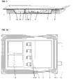
- Fig. 1 shows a first embodiment of a transformer element 1, preferably as a secondary part of an inductive charging system for electric vehicles or for at least partially electrically powered vehicles.
- the generated by a primary magnetic alternating field penetrates at least one secondary coil 2 and is then by means of an integrated in the housing 3 of the transformer element 1 electronics 4 in a charging current for in particular the traction battery 5 (see Fig. 3 ) of the vehicle.
- the housing 3 of the transformer element 1 can be made of any material, of course, with secondary coil 2 located inside the housing 3, of magnetically non-shielding material, such as plastic.
- the housing 3 also includes or includes a cup-shaped portion 6 of magnetically shielding material, preferably ferrite.
- This section 6 may be formed on the housing 3 itself or be a separately manufactured and connected to the housing 3 component.
- One side 7 of this section 6 is open and has, when the transmitter element 1 is operated as intended, away from the primary part.
- the electronics 4 located in the housing 3 is shielded from most of the magnetic field generated by the primary part.
- At least one secondary coil 2 preferably surrounds the pot-like section 6 on the outside thereof, wherein the magnetic shielding through the ferrite section 6 advantageously acts as a derivative or diversion of the magnetic field lines around sensitive components and through the secondary coil 2.
- the open side 7 of the housing 3 or its pot-like portion 6 is at least partially provided with a cover 8 also made of magnetic shielding material such as ferrite.
- the cover 8 preferably covers a larger area than the portion 6 - seen normal to the direction of the magnetic field lines - and thus surmounted both this section 6 and the secondary coil 2. If necessary, the edge of the cover 8 also on the sides of the Secondary coil 2 pulled around, in particular be pulled down, for example, applied to the underside of a vehicle, so that through the cover 8 a cup-shaped portion 6 oppositely oriented cup-shaped structure is formed.
- the secondary coil 2 and possibly also the interior of the housing 3, preferably also the interior of the pot-like portion 6, can be at least partially filled with a potting compound 9. This at least partially surrounds the components contained in the housing 3, preferably the secondary coil 2 and / or the electronics 4 in order to protect them against moisture and / or mechanical stresses, in particular bumps or vibrations during driving of the electric vehicle.
- the Fig. 2a and 2 B show a slightly different embodiment of an inventive transformer element 1a.
- the housing 3 is covered by a thin, lightweight plate 8a made of, for example, aluminum and closed to the outside.
- the cover 8 advantageously made of aluminum, copper or other good heat conducting material, the heat is dissipated by the electronics 4 in the environment and so the electronics 4 cooled.
- Such cooling arrangements can be provided in all embodiments according to the invention.
- the connections 12 for control and sensor lines from and to the electronics 4 as well as the connections 13 for the battery 5 to be charged are in the Fig. 2a and 2 B to see.
- the interior of the housing 3 may also be at least partially filled with the potting compound 9.
- This casting compound 9 at least partially surrounds the components contained in the housing 3, preferably the secondary coil 2 and / or the electronics 4.
- housing which includes the secondary coil 2 in its interior, wherein the secondary coil 2 is covered by a frame and preferably encapsulated.
- thin plates of ferrite or other magnetically shielding material may be arranged as wall and intermediate wall elements. These panels as wall elements can also form the cup-shaped shield 6 itself around the electronics 4, which is open on one side.
- the bottom of the housing adjoining the frame can also be covered with wall elements.
- the cover 8, 8a can be hinged on hinges or other suitable arrangements.
- the cover 8, 8a of whatever shape may also be provided on the inside with platelets of magnetically shielding material.
- the cover 8, 8a covers the housing 3, the pot-like portion 6 and also the secondary coil 2 and completed in the folded state an all-round shielding of the electronics 4 in the housing 3, which typically has a cuboid, preferably plate-shaped configuration to the outside.
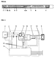
- the Fig. 3 finally shows an example of an electrical circuit diagram of a secondary part of an inductive energy transmission system using a transformer element 1, 1a according to the invention.
- the secondary coil 2 arranged in or on the housing 3, 3a is connected to a rectifier circuit 15 via at least one capacitor 14.
- a clamp circuit 16 (crowbar) is connected as overvoltage protection, further preferably an output filter 17 and finally the battery 5 to be charged, for example the traction battery of an electric vehicle.
- Via a control unit 18 parameters of said components are determined and their function controlled. Some or all of these components form the shielded electronics 4 of the transformer element. 1
Landscapes
- Engineering & Computer Science (AREA)
- Power Engineering (AREA)
- Computer Networks & Wireless Communication (AREA)
- Transportation (AREA)
- Mechanical Engineering (AREA)
- Charge And Discharge Circuits For Batteries Or The Like (AREA)
- Electric Propulsion And Braking For Vehicles (AREA)
Priority Applications (3)
| Application Number | Priority Date | Filing Date | Title |
|---|---|---|---|
| EP13169731.0A EP2808196A1 (fr) | 2013-05-29 | 2013-05-29 | Elément de transmission |
| PCT/IB2014/061653 WO2014191880A1 (fr) | 2013-05-29 | 2014-05-23 | Élément de transmission |
| EP14731377.9A EP3003773A1 (fr) | 2013-05-29 | 2014-05-23 | Élément de transmission |
Applications Claiming Priority (1)
| Application Number | Priority Date | Filing Date | Title |
|---|---|---|---|
| EP13169731.0A EP2808196A1 (fr) | 2013-05-29 | 2013-05-29 | Elément de transmission |
Publications (1)
| Publication Number | Publication Date |
|---|---|
| EP2808196A1 true EP2808196A1 (fr) | 2014-12-03 |
Family
ID=48520787
Family Applications (2)
| Application Number | Title | Priority Date | Filing Date |
|---|---|---|---|
| EP13169731.0A Withdrawn EP2808196A1 (fr) | 2013-05-29 | 2013-05-29 | Elément de transmission |
| EP14731377.9A Withdrawn EP3003773A1 (fr) | 2013-05-29 | 2014-05-23 | Élément de transmission |
Family Applications After (1)
| Application Number | Title | Priority Date | Filing Date |
|---|---|---|---|
| EP14731377.9A Withdrawn EP3003773A1 (fr) | 2013-05-29 | 2014-05-23 | Élément de transmission |
Country Status (2)
| Country | Link |
|---|---|
| EP (2) | EP2808196A1 (fr) |
| WO (1) | WO2014191880A1 (fr) |
Cited By (7)
| Publication number | Priority date | Publication date | Assignee | Title |
|---|---|---|---|---|
| DE102015214983A1 (de) * | 2015-08-06 | 2017-02-09 | Bayerische Motoren Werke Aktiengesellschaft | Integrierte Sekundärspule für induktives Laden eines Fahrzeugs |
| DE102016215503A1 (de) | 2016-08-18 | 2018-02-22 | Audi Ag | Elektromagnetisches Entkoppeln einer Antenneneinheit eines Kraftfahrzeugs von einer Energiekopplungseinrichtung |
| DE102017201433A1 (de) * | 2017-01-30 | 2018-08-02 | Bayerische Motoren Werke Aktiengesellschaft | Anordnung einer Ladeeinrichtung für eine Batterie in einem elektrisch betreibbaren Kraftwagen |
| DE102017103668A1 (de) * | 2017-02-22 | 2018-08-23 | Benteler Automobiltechnik Gmbh | Batterieträger mit Kunststoffunterschale und integrierter Induktionsleitung sowie Verfahren zu dessen Herstellung |
| DE102017214538A1 (de) * | 2017-08-21 | 2019-02-21 | Volkswagen Aktiengesellschaft | Batterie und Fahrzeug mit zumindest einer derartigen Batterie |
| DE102018201814A1 (de) * | 2018-02-06 | 2019-08-08 | Continental Automotive Gmbh | Gehäuse für eine Energieübertragungsspule und die zur Energieübertragung erforderlichen elektronischen Schaltungen |
| FR3094832A1 (fr) * | 2019-04-08 | 2020-10-09 | Institut Vedecom | Coupleur inductif et système de recharge par induction magnétique pour véhicules électriques et hybrides |
Families Citing this family (2)
| Publication number | Priority date | Publication date | Assignee | Title |
|---|---|---|---|---|
| DE102015223615B4 (de) * | 2015-11-30 | 2025-03-20 | Bayerische Motoren Werke Aktiengesellschaft | Sekundärspuleneinheit mit einer Service-Öffnung |
| DE102017207502A1 (de) * | 2017-05-04 | 2018-11-08 | Bayerische Motoren Werke Aktiengesellschaft | Spuleneinrichtung für einen Kraftwagen |
Citations (6)
| Publication number | Priority date | Publication date | Assignee | Title |
|---|---|---|---|---|
| US20110285349A1 (en) * | 2010-05-19 | 2011-11-24 | Qualcomm Incorporated | Adaptive wireless energy transfer system |
| US20120161696A1 (en) * | 2010-10-29 | 2012-06-28 | Qualcomm Incorporated | Wireless energy transfer via coupled parasitic resonators |
| EP2515314A1 (fr) * | 2009-12-17 | 2012-10-24 | Toyota Jidosha Kabushiki Kaisha | Blindage et véhicule équipé d'un tel blindage |
| WO2012144640A1 (fr) * | 2011-04-22 | 2012-10-26 | 矢崎総業株式会社 | Système d'alimentation électrique sans contact de type par résonance, dispositif du côté de la réception de puissance, et dispositif du côté de la transmission de puissance |
| WO2013017200A2 (fr) | 2011-08-02 | 2013-02-07 | Sew-Eurodrive Gmbh & Co. Kg | Appareil électronique, en particulier tête de transmission, et système de transfert d'énergie sans contact |
| EP2572427A2 (fr) | 2010-05-20 | 2013-03-27 | Sew-Eurodrive GmbH & Co. KG | Dispositif et procédé pour faire fonctionner un dispositif de transmission inductive d'énergie à un récepteur électrique |
Family Cites Families (2)
| Publication number | Priority date | Publication date | Assignee | Title |
|---|---|---|---|---|
| WO2007122788A1 (fr) * | 2006-03-24 | 2007-11-01 | Kabushiki Kaisha Toshiba | Dispositif recepteur de courant, appareil electronique l'utilisant et chargeur sans contact |
| US20120119698A1 (en) * | 2008-09-27 | 2012-05-17 | Aristeidis Karalis | Wireless energy transfer for vehicles |
-
2013
- 2013-05-29 EP EP13169731.0A patent/EP2808196A1/fr not_active Withdrawn
-
2014
- 2014-05-23 EP EP14731377.9A patent/EP3003773A1/fr not_active Withdrawn
- 2014-05-23 WO PCT/IB2014/061653 patent/WO2014191880A1/fr not_active Ceased
Patent Citations (6)
| Publication number | Priority date | Publication date | Assignee | Title |
|---|---|---|---|---|
| EP2515314A1 (fr) * | 2009-12-17 | 2012-10-24 | Toyota Jidosha Kabushiki Kaisha | Blindage et véhicule équipé d'un tel blindage |
| US20110285349A1 (en) * | 2010-05-19 | 2011-11-24 | Qualcomm Incorporated | Adaptive wireless energy transfer system |
| EP2572427A2 (fr) | 2010-05-20 | 2013-03-27 | Sew-Eurodrive GmbH & Co. KG | Dispositif et procédé pour faire fonctionner un dispositif de transmission inductive d'énergie à un récepteur électrique |
| US20120161696A1 (en) * | 2010-10-29 | 2012-06-28 | Qualcomm Incorporated | Wireless energy transfer via coupled parasitic resonators |
| WO2012144640A1 (fr) * | 2011-04-22 | 2012-10-26 | 矢崎総業株式会社 | Système d'alimentation électrique sans contact de type par résonance, dispositif du côté de la réception de puissance, et dispositif du côté de la transmission de puissance |
| WO2013017200A2 (fr) | 2011-08-02 | 2013-02-07 | Sew-Eurodrive Gmbh & Co. Kg | Appareil électronique, en particulier tête de transmission, et système de transfert d'énergie sans contact |
Cited By (11)
| Publication number | Priority date | Publication date | Assignee | Title |
|---|---|---|---|---|
| DE102015214983A1 (de) * | 2015-08-06 | 2017-02-09 | Bayerische Motoren Werke Aktiengesellschaft | Integrierte Sekundärspule für induktives Laden eines Fahrzeugs |
| DE102016215503A1 (de) | 2016-08-18 | 2018-02-22 | Audi Ag | Elektromagnetisches Entkoppeln einer Antenneneinheit eines Kraftfahrzeugs von einer Energiekopplungseinrichtung |
| US10384551B2 (en) | 2016-08-18 | 2019-08-20 | Audi Ag | Electromagnetic decoupling of an antenna unit of a motor vehicle from an energy coupling device |
| DE102017201433A1 (de) * | 2017-01-30 | 2018-08-02 | Bayerische Motoren Werke Aktiengesellschaft | Anordnung einer Ladeeinrichtung für eine Batterie in einem elektrisch betreibbaren Kraftwagen |
| DE102017103668A1 (de) * | 2017-02-22 | 2018-08-23 | Benteler Automobiltechnik Gmbh | Batterieträger mit Kunststoffunterschale und integrierter Induktionsleitung sowie Verfahren zu dessen Herstellung |
| DE102017214538A1 (de) * | 2017-08-21 | 2019-02-21 | Volkswagen Aktiengesellschaft | Batterie und Fahrzeug mit zumindest einer derartigen Batterie |
| DE102017214538B4 (de) | 2017-08-21 | 2023-10-26 | Volkswagen Aktiengesellschaft | Batterie und Fahrzeug mit zumindest einer derartigen Batterie |
| DE102018201814A1 (de) * | 2018-02-06 | 2019-08-08 | Continental Automotive Gmbh | Gehäuse für eine Energieübertragungsspule und die zur Energieübertragung erforderlichen elektronischen Schaltungen |
| DE102018201814B4 (de) | 2018-02-06 | 2024-05-16 | Vitesco Technologies GmbH | Gehäuse mit einer Energieübertragungsspule und die zur Energieübertragung erforderlichen elektronischen Schaltungen |
| FR3094832A1 (fr) * | 2019-04-08 | 2020-10-09 | Institut Vedecom | Coupleur inductif et système de recharge par induction magnétique pour véhicules électriques et hybrides |
| WO2020208313A1 (fr) * | 2019-04-08 | 2020-10-15 | Institut Vedecom | Coupleur inductif et système de recharge par induction magnétique pour véhicules électriques et hybrides |
Also Published As
| Publication number | Publication date |
|---|---|
| EP3003773A1 (fr) | 2016-04-13 |
| WO2014191880A1 (fr) | 2014-12-04 |
Similar Documents
| Publication | Publication Date | Title |
|---|---|---|
| EP2808196A1 (fr) | Elément de transmission | |
| EP3358921B1 (fr) | Dispositif électronique de puissance et véhicule correspondant | |
| DE102015201881A1 (de) | Elektrische Verbindungseinrichtung | |
| DE102014212540A1 (de) | Fahrzeug mit verbesserter Batterieabschirmung | |
| DE102017109321A1 (de) | EMV-Filter | |
| DE102016206378A1 (de) | Verbindungsanordnung eines ersten Bauelements an einem zweiten Bauelement, insbesondere für ein Fahrzeug, sowie Verbindungsvorrichtung, insbesondere für ein Fahrzeug | |
| DE102016200451A1 (de) | Berührgeschützte, verschraubbare elektrische Verbindung mit Toleranzausgleich | |
| DE102019119242A1 (de) | Akkupack | |
| DE102013217890A1 (de) | Elektromaschinengehäuse und Fahrzeugantrieb-Elektromaschine | |
| DE102016204460A1 (de) | Leistungselektronikmodul und Fahrzeugantriebsystem | |
| DE202015006792U1 (de) | Sicherheitsvorrichtung zum Schutz vor gefährlichen Berührungsspannungen an einem elektrischen Bauteil in eine relektrischen Baugruppe für ein Elektro- oder Hybridfahrzeug | |
| DE10347111B4 (de) | Integrierte Batteriemessklemme | |
| WO2016102057A1 (fr) | Module électronique pour un moteur électrique d'un entraînement de roue individuelle d'un véhicule à moteur, entraînement de roue individuelle et véhicule à moteur | |
| EP3150035B1 (fr) | Appareil électrique à conception modulaire | |
| DE102017214538B4 (de) | Batterie und Fahrzeug mit zumindest einer derartigen Batterie | |
| DE102013217836B4 (de) | Traktionsbatterie für ein Fahrzeug sowie Verfahren zur Herstellung dafür | |
| DE102016118965A1 (de) | Elektrischer Kompressor | |
| EP2710241B1 (fr) | Réservoir pour liquide | |
| DE102018215522A1 (de) | Zwischenkreiskondensator für eine Leistungselektronikanordnung sowie Leistungselektronikanordnung mit dem Zwischenkreiskondensator | |
| EP3836767A1 (fr) | Module électronique pour un outil électrique | |
| DE102018205949A1 (de) | Elektrisch antreibbares Kraftfahrzeug mit einer aus wenigstens einem Gehäuse mit Batteriezellen bestehenden Traktionsbatterie | |
| DE102014104437A1 (de) | Magnetischer Kreis zum dynamischen Laden von Elektrofahrzeugen | |
| EP3057388A1 (fr) | Boîtier pour composants haute tension | |
| DE19501895C2 (de) | Elektrische Schaltungsanordnung für Kraftfahrzeuge | |
| WO2022008210A1 (fr) | Unité électronique pour appareil électrique |
Legal Events
| Date | Code | Title | Description |
|---|---|---|---|
| PUAI | Public reference made under article 153(3) epc to a published international application that has entered the european phase |
Free format text: ORIGINAL CODE: 0009012 |
|
| 17P | Request for examination filed |
Effective date: 20130529 |
|
| AK | Designated contracting states |
Kind code of ref document: A1 Designated state(s): AL AT BE BG CH CY CZ DE DK EE ES FI FR GB GR HR HU IE IS IT LI LT LU LV MC MK MT NL NO PL PT RO RS SE SI SK SM TR |
|
| AX | Request for extension of the european patent |
Extension state: BA ME |
|
| STAA | Information on the status of an ep patent application or granted ep patent |
Free format text: STATUS: THE APPLICATION IS DEEMED TO BE WITHDRAWN |
|
| 18D | Application deemed to be withdrawn |
Effective date: 20150604 |