EP2808435A1 - Waschmaschine mit Einspritzdüse - Google Patents
Waschmaschine mit Einspritzdüse Download PDFInfo
- Publication number
- EP2808435A1 EP2808435A1 EP14170294.4A EP14170294A EP2808435A1 EP 2808435 A1 EP2808435 A1 EP 2808435A1 EP 14170294 A EP14170294 A EP 14170294A EP 2808435 A1 EP2808435 A1 EP 2808435A1
- Authority
- EP
- European Patent Office
- Prior art keywords
- injection
- fastener
- tub
- gasket
- washing machine
- Prior art date
- Legal status (The legal status is an assumption and is not a legal conclusion. Google has not performed a legal analysis and makes no representation as to the accuracy of the status listed.)
- Granted
Links
Images




Classifications
-
- D—TEXTILES; PAPER
- D06—TREATMENT OF TEXTILES OR THE LIKE; LAUNDERING; FLEXIBLE MATERIALS NOT OTHERWISE PROVIDED FOR
- D06F—LAUNDERING, DRYING, IRONING, PRESSING OR FOLDING TEXTILE ARTICLES
- D06F37/00—Details specific to washing machines covered by groups D06F21/00 - D06F25/00
- D06F37/26—Casings; Tubs
- D06F37/267—Tubs specially adapted for mounting thereto components or devices not provided for in preceding subgroups
-
- D—TEXTILES; PAPER
- D06—TREATMENT OF TEXTILES OR THE LIKE; LAUNDERING; FLEXIBLE MATERIALS NOT OTHERWISE PROVIDED FOR
- D06F—LAUNDERING, DRYING, IRONING, PRESSING OR FOLDING TEXTILE ARTICLES
- D06F39/00—Details of washing machines not specific to a single type of machines covered by groups D06F9/00 - D06F27/00
- D06F39/08—Liquid supply or discharge arrangements
- D06F39/088—Liquid supply arrangements
-
- D—TEXTILES; PAPER
- D06—TREATMENT OF TEXTILES OR THE LIKE; LAUNDERING; FLEXIBLE MATERIALS NOT OTHERWISE PROVIDED FOR
- D06F—LAUNDERING, DRYING, IRONING, PRESSING OR FOLDING TEXTILE ARTICLES
- D06F37/00—Details specific to washing machines covered by groups D06F21/00 - D06F25/00
- D06F37/26—Casings; Tubs
- D06F37/266—Gaskets mounted between tub and casing around the loading opening
-
- D—TEXTILES; PAPER
- D06—TREATMENT OF TEXTILES OR THE LIKE; LAUNDERING; FLEXIBLE MATERIALS NOT OTHERWISE PROVIDED FOR
- D06F—LAUNDERING, DRYING, IRONING, PRESSING OR FOLDING TEXTILE ARTICLES
- D06F39/00—Details of washing machines not specific to a single type of machines covered by groups D06F9/00 - D06F27/00
- D06F39/02—Devices for adding soap or other washing agents
- D06F39/024—Devices for adding soap or other washing agents mounted on the agitator or the rotating drum; Free body dispensers
-
- D—TEXTILES; PAPER
- D06—TREATMENT OF TEXTILES OR THE LIKE; LAUNDERING; FLEXIBLE MATERIALS NOT OTHERWISE PROVIDED FOR
- D06F—LAUNDERING, DRYING, IRONING, PRESSING OR FOLDING TEXTILE ARTICLES
- D06F39/00—Details of washing machines not specific to a single type of machines covered by groups D06F9/00 - D06F27/00
- D06F39/12—Casings; Tubs
-
- D—TEXTILES; PAPER
- D06—TREATMENT OF TEXTILES OR THE LIKE; LAUNDERING; FLEXIBLE MATERIALS NOT OTHERWISE PROVIDED FOR
- D06F—LAUNDERING, DRYING, IRONING, PRESSING OR FOLDING TEXTILE ARTICLES
- D06F35/00—Washing machines, apparatus, or methods not otherwise provided for
- D06F35/002—Washing machines, apparatus, or methods not otherwise provided for using bubbles
Definitions
- the present invention relates to a washing machine having an improved wash water injection configuration.
- washing machines serve to wash or dry laundry.
- wash water introduced from an external source may be subjected to circulation and injection.
- a typical washing machine includes a cabinet defining an external appearance of the washing machine, a tub placed within the cabinet, and a drum rotatably placed within the tub.
- a gasket to reduce vibration may be interposed between the tub and the cabinet.
- An injection nozzle to inject wash water may be located at the gasket. Since the gasket may be formed of a high ductility material, such as rubber, etc., installing the injection nozzle to the gasket may cause leakage of wash water from the tub due to change in the direction of the injection nozzle.
- a position of the injection nozzle may be changed by injection pressure of wash water or vibration of the drum during washing.
- a washing machine includes a cabinet having an opening, a tub placed within the cabinet, a drum rotatably placed within the tub, a gasket connecting the tub and the cabinet to each other to reduce vibration of the tub to be transmitted to the cabinet during rotation of the drum, and an injection device configured to inject wash water into the tub, wherein the injection device includes an injection nozzle into which wash water is introduced, the injection nozzle penetrating the gasket, an injection guide configured to guide wash water introduced through the injection nozzle so as to inject the wash water, and a fastener penetrating the gasket to fix a position of the injection nozzle.
- the fastener may be spaced apart from the injection nozzle in parallel.
- the fastener may be located at an exit end of the an injection flow path defined in the injection guide.
- the fastener may include a fastener flow path communicating with the interior of the tub.
- the washing machine may include a bubble generation device configured to generate and supply bubbles into the tub, and interior air of the drum may be guided to the bubble generation device through the fastener flow path.
- At least one of the injection nozzle and the fastener may include a stepped portion protruding from an outer circumference thereof to allow the injection nozzle to be supported by an outer surface of the gasket.
- the gasket may include a through-hole for penetration of at least a portion of the injection device, and a support portion protruding outward from the gasket around the through-hole to support the stepped portion.
- the injection guide may include an upper guide, by which the injection nozzle and the fastener are supported, a lower guide facing a nozzle flow path defined in the injection nozzle, the lower guide being inclined toward the drum, and a lateral guide connecting the upper guide and the lower guide to each other.
- the upper guide may include a bent surface inclined toward the drum and defining an upper boundary of wash water injected via the injection guide.
- One end of a fastener flow path defined in the fastener may be located on the bent surface.
- the injection device may include at least one injection device located in a circumferential direction of the gasket.
- a washing machine includes a cabinet, a tub placed within the cabinet, a drum rotatably placed within the tub, a gasket connecting the cabinet and the tub to each other, and an injection device penetrating the gasket, wherein the injection device includes an injection nozzle having a nozzle seat supported by a support portion protruding from the gasket to prevent the injection device from being separated in the Z-axis corresponding to a longitudinal direction of the injection nozzle, and a nozzle flow path penetrating the gasket to communicate the interior and the exterior of the gasket with each other, and a fastener spaced apart from the injection nozzle in parallel.
- the injection device may include an injection guide configured to inject wash water introduced through the nozzle flow path into the drum.
- the injection nozzle and the fastener may be spaced apart from each other and coupled to the injection guide.
- the fastener may be located closer to the exit end of the injection guide than the injection nozzle.
- the fastener may include a fastener flow path communicating with the interior of the tub.
- the washing machine may include a bubble generation device to generate and supply bubbles into the tub, and interior air of the drum may be guided to the bubble generation device through the fastener flow path.
- the injection device may include at least one injection device located in a circumferential direction of the gasket.
- FIG. 1 is a view illustrating a washing machine according to an embodiment.
- the washing machine according to an embodiment, as exemplarily illustrated in FIG. 1 , includes a cabinet 10 defining an external appearance of the washing machine, a tub 20 in which wash water is received, the tub 20 being installed within the cabinet 10 via suspension, a drum 30 rotatably installed within the tub 20, a door 12 to open or close a laundry opening 11 for introduction of laundry, and a drive motor 40 installed to a rear surface of the tub 20 to generate torque required to rotate the drum 30.
- the drum 30 is rotated by the drive motor 40 after laundry is introduced into the drum 30 through the laundry opening 11 opened by the door 12, the laundry within the drum 30 is washed by being raised upward and dropping.
- the drum 30 has communication holes 31 to allow wash water of the tub 20 to be introduced into the drum 30.
- Lifters 32 to raise laundry upward may be arranged inside the drum 30.
- the drive motor 40 includes a stator 41 installed to the tub 20, a rotor 42 to implement rotation via interaction with the stator 41, and a rotating shaft 43 having one end coupled to the rotor 42 and the other end penetrating the rear surface of the tub 20 to thereby be installed to the drum 30, the rotating shaft 43 being rotated along with the rotor 42 to rotate the drum 30.
- a water supply device 50 to supply water into the tub 20 may be disposed above the tub 20, and a drain device 60 to discharge wash water from the tub 20 may be disposed below the tub 20.
- the water supply device 50 includes a first water supply pipe 51 connected to an external water supply source, a water supply valve 52 to open or close the first water supply pipe 51, a detergent feeder 53 to mix detergent with wash water supplied through the first water supply pipe 51, a second water supply pipe 54 connecting the detergent feeder 53 and the tub 20 to each other to guide a mixture of the detergent and wash water to the tub 20, and a third water supply pipe 55 diverged from the first water supply pipe 51 and connected to an injection device 100.
- the drain device 60 includes a pump 61 to pump wash water from the tub 20, a first drainpipe 62 connecting the tub 20 and the pump 61 to each other to guide wash water of the tub 20 to the pump 61, and a second drainpipe 63 connected to the pump 61 and extending outward from the cabinet 1 to outwardly discharge wash water.
- a gasket 80 may be interposed between the cabinet 10 and the tub 20.
- the gasket 80 may be coupled at one side thereof to the cabinet 10 and at the other side thereof to the periphery of a front opening of the tub 20. This prevents wash water stored in the tub 20 from leaking from a gap between the tub 20 and the cabinet 10.
- the gasket 80 may have a corrugated peripheral portion to absorb vibration of the tub 20.
- the gasket 80 may include a tub coupling portion 81 fastened to the tub 20, a cabinet coupling portion 82 fastened to the cabinet 10, and a connection portion 83 connecting the tub coupling portion 81 and the cabinet coupling portion 82 to each other, the connection portion 83 being corrugated to absorb shock.
- the gasket 80 may be formed of an elastic material, and may contain additives to increase elasticity and rigidity thereof.
- the gasket 80 is provided with a first injection device 101 and a second injection device 102.
- injection of wash water may use the two injection devices 100, however, the disclosure is not limited thereto, and the injection devices 100 may be installed to inject wash water into the drum 30 or toward the door 12 in at least one direction.
- an embodiment may provide the gasket 80 with the two injection devices 100, the injection devices may be provided at various positions for injection of wash water into the drum 30.
- FIG. 2 is a view illustrating arrangement of the injection device according to an embodiment
- FIG. 3 is a view illustrating a coupled state of the injection device according to an embodiment
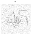
- FIG. 4 is a sectional view of the injection device according to an embodiment.
- the injection devices 100 may be provided at the gasket 80, for example, the injection devices may be provided at the connection portion 83 of the gasket 80.
- the number and position of the injection devices 100 are not limited to the above description, and one or more injection devices may be arranged in a circumferential direction of the gasket 80. According to an embodiment, for convenience of description, two first and second injection devices 101 and 102 may be arranged at symmetrical left and right positions of an upper end of the gasket 80.
- Each injection device 100 may include an injection nozzle 110, an injection guide 120, and a fastener 130.
- the injection nozzle 110, the injection guide 120, and the fastener 130 may be separate elements, or may be integrally formed via injection molding.
- the injection nozzle 110 may be connected to a water supply pipe to inject wash water into the drum 30. Although a wash water supply path to the injection nozzle 110 is not specifically defined, according to an embodiment, the injection nozzle 110 may be connected to the third water supply pipe 55 diverged from the first water supply pipe 51.
- the injection nozzle 110 has a nozzle flow path 112a for passage of wash water.
- One end of the injection nozzle 110 may be connected to the water supply pipe and the other end of the injection nozzle 110 may be coupled to the injection guide 120.
- the injection nozzle 110 may be separate from the injection guide 120, or may be integrally formed with the injection guide 120.
- the injection nozzle 110 penetrates the connection portion 83 of the gasket 80.
- the injection nozzle 110 may have a stepped portion 114 around an outer circumference thereof and may be supported by an outer surface of the gasket 80 by the stepped portion 114.
- the other end of the injection nozzle 110 may be supported by the injection guide 120 that supports an inner surface of the gasket 80.
- the injection nozzle 110 may be installed to the gasket 80 without a risk of separation.
- the stepped portion 114 may be formed at the injection nozzle 110, the stepped portion 114 may be formed at the fastener 130.
- the injection nozzle 110 and the fastener 130 may be provided respectively with a nozzle seat 116 and a seat 136, which are coupled to the gasket 80 between the respective stepped portions 114 and 134 and the injection guide 120. Lengths of the nozzle seat 116 and the seat 136 may vary based on a thickness of the gasket 80.
- the injection guide 120 may be provided at the other end of the injection nozzle 110 to inject wash water passing through the nozzle flow path 112a.
- the injection guide 120 may have a fanwise injection flow path 120a, a width of which gradually increases toward an exit end thereof. This shape ensures that wash water is injected over a wide range into the drum 30.
- the injection guide 120 may include a lower guide 122, an upper guide 124, and a lateral guide 126.
- the lower guide 122 may be located to face an exit end 112b of the nozzle flow path 112a, and may obliquely extend into the drum 30. A width of the lower guide 122 may increase toward the exit end of the injection flow path 120a.
- the upper guide 124 supports the injection nozzle 110 and the fastener 130 and defines an upper boundary of wash water.
- the lateral guide 126 may extend to connect the upper guide 124 and the lower guide 122 to each other.
- Wash water introduced into the nozzle flow path 112a may have upper and lower boundaries defined by the upper guide 124 and the lower guide 122 and a width direction boundary defined by the lateral guide 126.
- the upper guide 124 may have a bent surface 125 such that at least a portion of the upper guide 124 proximate to the injection flow path 120a is inclined into the drum 30.
- the bent surface 125 defines the upper boundary of wash water passing through the injection flow path 120a.
- Both the fastener 130 and the injection nozzle 110 may be supported by the upper guide 124 of the injection guide 120.
- the fastener 130 may be spaced apart from the injection nozzle 110 and function to prevent change in the direction of the injection nozzle 110.
- the fastener 130 may be located in parallel to the Z-axis and be integrated with the upper guide 124.
- the fastener 130 penetrates the gasket 80 to thereby be supported by the gasket 80. Consequently, the fastener 130 may prevent the injection nozzle 110 from being tilted to the X-axis or the Y-axis perpendicular to the Z-axis.
- Wash water may be injected into the drum 30 by passing through the nozzle flow path 112a of the injection nozzle 110 and the injection flow path 120a of the injection guide 120. Both the injection flow path 120a and the nozzle flow path 112a may be angled to each other, which may cause direction change due to injection pressure of wash water.
- the fastener 130 may be located at the exit end of the injection flow path 120a of the injection guide 120. That is, the fastener 130 may be positioned on the injection guide 120 so as to be spaced apart, for example, in parallel, from the injection nozzle 110 toward the exit end of the injection flow path 120a.
- the gasket 80 may have through-holes 84 such that the injection nozzle 110 and the fastener 130 penetrate the gasket 80, and support portions 85 protruding outward from the gasket 80 around the through-holes 84.
- the injection nozzle 110 and the fastener 130 may be respectively provided with the stepped portions 114 and 134, and thus are supported by the outer surface of the gasket 80.
- the stepped portions 114 and 134 may be directly supported by the through-holes 84, the stepped portions 114 and 134 may be supported by ends of the support portions 85 to allow the injection device 100 to be supported by the gasket 80.
- the stepped portions 114 and 134 of the injection device 100 may be supported by the outer surface of the gasket 80 and the inner surface of the gasket 80 may be supported by the upper guide 124.
- a positioning recess 86 may be formed in the support portion 85, and a fixing boss 118 formed at the injection nozzle 110 or the fastener 130 may be seated in the positioning recess 86.
- the positioning recess 86 is formed in one side of the support portion 85, and the fixing boss 118 is formed at an outer circumference of the injection nozzle 110 or the fastener 130 to correspond to the positioning recess 86. According to an embodiment, the fixing boss 118 is formed at the injection nozzle 110.
- the positioning recess 86 and the fixing boss 118 function to prevent change in the position of the injection nozzle 110, and to indicate a coupling position to assist the injection device 100 in being coupled to the gasket 80 at an accurate position without direction change.
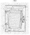
- FIG. 5 is a view illustrating a washing machine according to an embodiment
- FIG. 6 is a view illustrating arrangement of an injection device according to an embodiment
- FIG. 7 is a sectional view of the injection device according to an embodiment
- FIG. 8 is a perspective view of the injection device according to an embodiment.
- a bubble generation device 70 may be disposed below the tub 20 to generate and supply bubbles into the tub 20.
- the bubble generation device 70 may be connected to a transfer pipe 64 which may be in turn connected to the pump 61 such that wash water is supplied from the pump 61 to the transfer pipe 64.
- the bubble generation device 70 may be connected to a connection pipe 13 which may be in turn connected to the top of the tub 20 such that air may be transferred to the bubble generation device 70.
- One end of the connection pipe 13 may be connected to the bubble generation device 70, and the other end of the connection pipe 13 positioned higher than the level of wash water received in the tub 20 such that interior air of the tub 20 may be suctioned into the connection pipe 13.
- bubbles may be generated and supplied into the tub 20 as wash water transferred from the pump 61 and air transferred through the connection pipe 13 are mixed in the bubble generation device 70.
- the injection device 100 may include a third injection device 103.
- the pump 61 may be provided with a circulation pipe 65 connected to the third injection device 103. Wash water supplied from the pump 61 through the circulation pipe 65 may be directed to the injection nozzle 110 of the third injection device 103, and then may be directed into the drum 30.
- the fastener 130 may be spaced apart from the Z-axis of the injection nozzle 110 and functions to prevent change in the direction of the injection device 110.
- the fastener 130 may function to transfer interior air of the tub 20 to the bubble generation device 70 through a fastener flow path 130a formed therein.
- connection pipe 13 connected to the bubble generation device 70 may be coupled to the fastener 130 such that interior air of the tub 20 is suctioned into the bubble generation device 70.
- One end of the fastener flow path 130a may communicate with the connection pipe 13 connected to the bubble generation device 70, and the other end of the fastener flow path 130a may be located at the bent surface 125 of the upper guide 124 to communicate with the interior of the tub 20.
- the upper boundary of wash water injected through the injection flow path 120a may be defined by the bent surface 125 and the end of the fastener flow path 130a may be located on the bent surface 125, it may be possible to prevent wash water from flowing backward through the fastener flow path 130a.
- a washing machine having the above described configuration is additionally described.
- the washing machine includes the cabinet 10, the tub 20 placed within the cabinet 10, the drum 30 rotatably placed within the tub 20, the gasket 80 connecting the cabinet 10 and the tub 20 to each other, and the injection device 100 penetrating the gasket 80.
- the injection device 100 includes the injection nozzle 110, which includes the nozzle seat 116 supported by the support portion 85 protruding from the gasket 80 to prevent the injection device 100 from being separated in the Z-axis corresponding to a longitudinal direction of the injection nozzle 110 and the nozzle flow path 112a penetrating the gasket 80 to communicate the interior and the exterior of the gasket 80 with each other, and the fastener 130 spaced apart from the injection nozzle 110 to prevent the injection device 100 from being tilted to the X-axis or the Y-axis perpendicular to the Z-axis.
- the injection device 100 may include the injection guide 120 to inject wash water introduced through the nozzle flow path 112a into the drum 30.
- the injection nozzle 110 and the fastener 130 may be coupled to the injection guide 120 at positions spaced apart from each other.
- the fastener 130 may be located closer to the exit end of the injection guide 120 than the injection nozzle 110.
- the fastener 130 may include the fastener flow path 130a communicating with the interior of the tub 20.
- the bubble generation device 70 to generate and supply bubbles into the tub 30 may be provided, and interior air of the drum 30 may be directed to the bubble generation device 70 through the fastener flow path 130a.
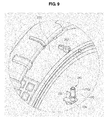
- FIG. 9 is a view illustrating a coupled state of an injection device according to an embodiment.
- An injection device 210 may include an injection nozzle 220, an injection guide 224, and a fastener 230.
- the fastener 230 may extend from the injection nozzle 220 in a radial direction from an axial nozzle flow path 220a of the injection nozzle 220.
- a through-hole 202 of a gasket 200 may have a combined shape of the circular cross section of the injection nozzle 220 and a bar-shaped cross section of the fastener 230.
- the injection device 100 may be coupled and fixed to the gasket 80, and function to inject wash water from the exterior to the interior of the gasket 80 or to discharge interior air of the drum 30 to the exterior of the gasket 80.
- the gasket 80 may have a through-hole 84 for insertion of the injection device 100.
- a plurality of through-holes 84 may be provided for injection of both the fastener 130 and the injection nozzle 110.
- the injection nozzle 110 and the fixing boss 118 may be positioned to correspond to the positioning recess 86 of the support portion 85.
- the stepped portions 114 and 134 are supported by the ends of the support portions 85 and the upper guide 124 of the injection guide 120 is supported by the inner surface of the gasket 80, it may be possible to prevent the injection device 100 from being separated from the gasket 80.
- the fastener 130 may prevent change in the direction of the injection nozzle 110.
- a technological advantage of an embodiment includes a washing machine having an improved configuration of an injection device and may ensure easy coupling of the injection device and prevent change in the direction of the installed injection device, thereby maintaining a constant wash water injection direction.
Landscapes
- Engineering & Computer Science (AREA)
- Textile Engineering (AREA)
- Detail Structures Of Washing Machines And Dryers (AREA)
- Main Body Construction Of Washing Machines And Laundry Dryers (AREA)
- Accessory Of Washing/Drying Machine, Commercial Washing/Drying Machine, Other Washing/Drying Machine (AREA)
Applications Claiming Priority (2)
| Application Number | Priority Date | Filing Date | Title |
|---|---|---|---|
| US201361828285P | 2013-05-29 | 2013-05-29 | |
| KR1020130061294A KR20140140435A (ko) | 2013-05-29 | 2013-05-29 | 세탁기 |
Publications (2)
| Publication Number | Publication Date |
|---|---|
| EP2808435A1 true EP2808435A1 (de) | 2014-12-03 |
| EP2808435B1 EP2808435B1 (de) | 2019-11-20 |
Family
ID=50828745
Family Applications (1)
| Application Number | Title | Priority Date | Filing Date |
|---|---|---|---|
| EP14170294.4A Active EP2808435B1 (de) | 2013-05-29 | 2014-05-28 | Waschmaschine mit Einspritzdüse |
Country Status (4)
| Country | Link |
|---|---|
| US (1) | US20140352363A1 (de) |
| EP (1) | EP2808435B1 (de) |
| KR (1) | KR20140140435A (de) |
| CN (1) | CN104213372A (de) |
Cited By (6)
| Publication number | Priority date | Publication date | Assignee | Title |
|---|---|---|---|---|
| WO2020015982A1 (en) | 2018-07-19 | 2020-01-23 | Arcelik Anonim Sirketi | An integrated spray head |
| RU2756501C1 (ru) * | 2018-06-27 | 2021-10-01 | ЭлДжи ЭЛЕКТРОНИКС ИНК. | Стиральная машина |
| RU2764136C1 (ru) * | 2018-06-27 | 2022-01-13 | ЭлДжи ЭЛЕКТРОНИКС ИНК. | Стиральная машина |
| CN114606721A (zh) * | 2018-06-27 | 2022-06-10 | Lg电子株式会社 | 洗衣机 |
| US11866879B2 (en) | 2017-11-09 | 2024-01-09 | Lg Electronics Inc. | Laundry treating apparatus having a nozzle |
| RU2838292C2 (ru) * | 2018-06-27 | 2025-04-14 | ЭлДжи ЭЛЕКТРОНИКС ИНК. | Стиральная машина |
Families Citing this family (28)
| Publication number | Priority date | Publication date | Assignee | Title |
|---|---|---|---|---|
| KR102549142B1 (ko) * | 2016-01-26 | 2023-06-30 | 삼성전자주식회사 | 세탁기 |
| RU2734407C1 (ru) | 2016-12-28 | 2020-10-16 | ЭлДжи ЭЛЕКТРОНИКС ИНК. | Стиральная машина |
| RU2732110C1 (ru) | 2016-12-28 | 2020-09-11 | ЭлДжи ЭЛЕКТРОНИКС ИНК. | Стиральная машина |
| KR102642445B1 (ko) * | 2016-12-28 | 2024-02-28 | 엘지전자 주식회사 | 세탁기 |
| KR102643584B1 (ko) * | 2016-12-28 | 2024-03-04 | 엘지전자 주식회사 | 세탁기 |
| KR102486309B1 (ko) * | 2017-06-28 | 2023-01-10 | 삼성전자주식회사 | 세탁기 및 세탁기의 다이어프램 조립체 |
| KR102573125B1 (ko) * | 2017-12-28 | 2023-08-30 | 엘지전자 주식회사 | 세탁기 |
| WO2019161898A1 (en) * | 2018-02-22 | 2019-08-29 | Electrolux Appliances Aktiebolag | Laundry washing machine equipped with a liquid supply line |
| CN110468558A (zh) * | 2018-05-10 | 2019-11-19 | 青岛海尔滚筒洗衣机有限公司 | 滚筒洗衣机及其喷淋系统和密封窗垫 |
| CN110607662A (zh) * | 2018-06-15 | 2019-12-24 | 青岛海尔滚筒洗衣机有限公司 | 滚筒洗衣机及其喷淋系统 |
| RU2754896C1 (ru) * | 2018-06-27 | 2021-09-08 | ЭлДжи ЭЛЕКТРОНИКС ИНК. | Стиральная машина |
| KR102655311B1 (ko) * | 2018-06-27 | 2024-04-05 | 엘지전자 주식회사 | 세탁기 |
| US11692296B2 (en) | 2018-06-27 | 2023-07-04 | Lg Electronics Inc. | Washing machine |
| JP7208268B2 (ja) * | 2018-06-27 | 2023-01-18 | エルジー エレクトロニクス インコーポレイティド | 洗濯機 |
| WO2020004911A1 (en) | 2018-06-27 | 2020-01-02 | Lg Electronics Inc. | Washing machine |
| KR102764828B1 (ko) | 2018-06-27 | 2025-02-11 | 엘지전자 주식회사 | 세탁기 |
| WO2020004905A1 (en) | 2018-06-27 | 2020-01-02 | Lg Electronics Inc. | Washing machine |
| WO2020004907A1 (en) * | 2018-06-27 | 2020-01-02 | Lg Electronics Inc. | Washing machine and method for assembling the same |
| WO2020004909A1 (en) * | 2018-06-27 | 2020-01-02 | Lg Electronics Inc. | Washing machine |
| DE102018215122A1 (de) * | 2018-09-06 | 2020-03-12 | Meiko Maschinenbau Gmbh & Co. Kg | Reinigungsvorrichtung zur Reinigung von Reinigungsgut und Verfahren zur Herstellung einer Reinigungsvorrichtung |
| AU2020200745B2 (en) * | 2019-02-01 | 2021-10-21 | Lg Electronics Inc. | Apparatus for treating laundry |
| KR102892505B1 (ko) * | 2019-12-09 | 2025-11-28 | 삼성전자주식회사 | 다이어프램 조립체 및 이를 포함하는 세탁기 |
| CN111118818A (zh) * | 2020-01-06 | 2020-05-08 | 青岛海尔滚筒洗衣机有限公司 | 用于滚筒洗衣机的蒸汽洗控制方法 |
| CN113073447A (zh) * | 2020-01-06 | 2021-07-06 | 青岛海尔滚筒洗衣机有限公司 | 滚筒洗衣机 |
| US11466393B2 (en) * | 2020-03-06 | 2022-10-11 | Whirlpool Corporation | Spray system for an appliance having a flexible spray membrane having a separable seam |
| KR20220056143A (ko) * | 2020-10-27 | 2022-05-04 | 엘지전자 주식회사 | 의류처리장치 |
| EP4008828B1 (de) * | 2020-12-02 | 2026-02-18 | LG Electronics Inc. | Wäschebehandlungsvorrichtung |
| US20240068149A1 (en) * | 2022-08-30 | 2024-02-29 | Whirlpool Corporation | Sprayer assembly for laundry appliance |
Citations (7)
| Publication number | Priority date | Publication date | Assignee | Title |
|---|---|---|---|---|
| DE4128904A1 (de) * | 1991-08-30 | 1993-03-04 | Bosch Siemens Hausgeraete | Waschmaschine mit einer faltenmanschette |
| EP1505191A1 (de) * | 2003-08-07 | 2005-02-09 | Lg Electronics Inc. | Waschmaschine |
| DE102004036672B3 (de) * | 2004-07-28 | 2005-12-29 | Miele & Cie. Kg | Stirnseitig beschickbare Trommelwaschmaschine mit Beleuchtungs- und/oder Einsprüheinrichtung der Faltenbalgdichtung |
| US20100251784A1 (en) * | 2009-04-03 | 2010-10-07 | Lg Electronics Inc. | Fabric treating machine |
| US20110099728A1 (en) * | 2009-11-02 | 2011-05-05 | Lg Electronics Inc. | Method for washing and washing machine |
| US20120204607A1 (en) * | 2011-02-15 | 2012-08-16 | Samsung Electronics Co., Ltd. | Bubble generating device and washing machine having the same |
| WO2012141411A2 (ko) * | 2011-04-14 | 2012-10-18 | 엘지전자 주식회사 | 세탁기 |
-
2013
- 2013-05-29 KR KR1020130061294A patent/KR20140140435A/ko not_active Withdrawn
-
2014
- 2014-05-28 EP EP14170294.4A patent/EP2808435B1/de active Active
- 2014-05-28 US US14/289,079 patent/US20140352363A1/en not_active Abandoned
- 2014-05-29 CN CN201410234069.0A patent/CN104213372A/zh active Pending
Patent Citations (8)
| Publication number | Priority date | Publication date | Assignee | Title |
|---|---|---|---|---|
| DE4128904A1 (de) * | 1991-08-30 | 1993-03-04 | Bosch Siemens Hausgeraete | Waschmaschine mit einer faltenmanschette |
| EP1505191A1 (de) * | 2003-08-07 | 2005-02-09 | Lg Electronics Inc. | Waschmaschine |
| DE102004036672B3 (de) * | 2004-07-28 | 2005-12-29 | Miele & Cie. Kg | Stirnseitig beschickbare Trommelwaschmaschine mit Beleuchtungs- und/oder Einsprüheinrichtung der Faltenbalgdichtung |
| US20100251784A1 (en) * | 2009-04-03 | 2010-10-07 | Lg Electronics Inc. | Fabric treating machine |
| US20110099728A1 (en) * | 2009-11-02 | 2011-05-05 | Lg Electronics Inc. | Method for washing and washing machine |
| US20120204607A1 (en) * | 2011-02-15 | 2012-08-16 | Samsung Electronics Co., Ltd. | Bubble generating device and washing machine having the same |
| WO2012141411A2 (ko) * | 2011-04-14 | 2012-10-18 | 엘지전자 주식회사 | 세탁기 |
| US20140033449A1 (en) * | 2011-04-14 | 2014-02-06 | Lg Electronics Inc. | Method for washing |
Cited By (11)
| Publication number | Priority date | Publication date | Assignee | Title |
|---|---|---|---|---|
| US11866879B2 (en) | 2017-11-09 | 2024-01-09 | Lg Electronics Inc. | Laundry treating apparatus having a nozzle |
| US11920283B2 (en) | 2017-11-09 | 2024-03-05 | Lg Electronics Inc. | Washing machine having circulation nozzles |
| US12503807B2 (en) | 2017-11-09 | 2025-12-23 | Lg Electronics Inc. | Laundry treating apparatus having a nozzle |
| RU2756501C1 (ru) * | 2018-06-27 | 2021-10-01 | ЭлДжи ЭЛЕКТРОНИКС ИНК. | Стиральная машина |
| RU2764136C1 (ru) * | 2018-06-27 | 2022-01-13 | ЭлДжи ЭЛЕКТРОНИКС ИНК. | Стиральная машина |
| CN114606721A (zh) * | 2018-06-27 | 2022-06-10 | Lg电子株式会社 | 洗衣机 |
| US11519121B2 (en) | 2018-06-27 | 2022-12-06 | Lg Electronics Inc. | Washing machine |
| CN114606721B (zh) * | 2018-06-27 | 2024-01-05 | Lg电子株式会社 | 洗衣机 |
| US11879200B2 (en) | 2018-06-27 | 2024-01-23 | Lg Electronics Inc. | Washing machine having circulation nozzles |
| RU2838292C2 (ru) * | 2018-06-27 | 2025-04-14 | ЭлДжи ЭЛЕКТРОНИКС ИНК. | Стиральная машина |
| WO2020015982A1 (en) | 2018-07-19 | 2020-01-23 | Arcelik Anonim Sirketi | An integrated spray head |
Also Published As
| Publication number | Publication date |
|---|---|
| CN104213372A (zh) | 2014-12-17 |
| KR20140140435A (ko) | 2014-12-09 |
| US20140352363A1 (en) | 2014-12-04 |
| EP2808435B1 (de) | 2019-11-20 |
Similar Documents
| Publication | Publication Date | Title |
|---|---|---|
| EP2808435B1 (de) | Waschmaschine mit Einspritzdüse | |
| CN110886064B (zh) | 衣物处理装置用提升器 | |
| CN103266453B (zh) | 织物处理机 | |
| EP2391760B1 (de) | Waschmaschine | |
| KR101692726B1 (ko) | 세탁장치 | |
| KR102448494B1 (ko) | 세탁기 | |
| KR101474501B1 (ko) | 배수펌프 및 이를 갖춘 세탁기 | |
| KR102557404B1 (ko) | 세탁기 | |
| KR20130016932A (ko) | 세탁기 | |
| KR20110020364A (ko) | 세탁기, 세탁기의 이너터브 및 그 조립방법 | |
| CN102587091A (zh) | 排水软管和具有该排水软管的洗涤机 | |
| CN202559115U (zh) | 洗衣机 | |
| CN110366617A (zh) | 洗衣机 | |
| US20060081018A1 (en) | Washing machine | |
| CN107923106A (zh) | 洗衣机 | |
| JP6936143B2 (ja) | 衣類処理装置 | |
| KR100813674B1 (ko) | 세탁기의 세탁보조제 저장장치 | |
| KR20200022691A (ko) | 세탁장치 | |
| KR20130116633A (ko) | 뎀핑장치를 구비하는 세탁기 | |
| KR102852918B1 (ko) | 송수장치 및 이를 포함하는 세탁기 | |
| KR102557577B1 (ko) | 세탁장치 | |
| CN111684120B (zh) | 洗涤物处理设备 | |
| KR20140060836A (ko) | 드럼 세탁기 | |
| KR102598162B1 (ko) | 세탁기 | |
| KR102281193B1 (ko) | 의류처리장치용 리프터 |
Legal Events
| Date | Code | Title | Description |
|---|---|---|---|
| PUAI | Public reference made under article 153(3) epc to a published international application that has entered the european phase |
Free format text: ORIGINAL CODE: 0009012 |
|
| 17P | Request for examination filed |
Effective date: 20140528 |
|
| AK | Designated contracting states |
Kind code of ref document: A1 Designated state(s): AL AT BE BG CH CY CZ DE DK EE ES FI FR GB GR HR HU IE IS IT LI LT LU LV MC MK MT NL NO PL PT RO RS SE SI SK SM TR |
|
| AX | Request for extension of the european patent |
Extension state: BA ME |
|
| R17P | Request for examination filed (corrected) |
Effective date: 20150603 |
|
| RBV | Designated contracting states (corrected) |
Designated state(s): AL AT BE BG CH CY CZ DE DK EE ES FI FR GB GR HR HU IE IS IT LI LT LU LV MC MK MT NL NO PL PT RO RS SE SI SK SM TR |
|
| GRAP | Despatch of communication of intention to grant a patent |
Free format text: ORIGINAL CODE: EPIDOSNIGR1 |
|
| STAA | Information on the status of an ep patent application or granted ep patent |
Free format text: STATUS: GRANT OF PATENT IS INTENDED |
|
| INTG | Intention to grant announced |
Effective date: 20190604 |
|
| GRAS | Grant fee paid |
Free format text: ORIGINAL CODE: EPIDOSNIGR3 |
|
| GRAA | (expected) grant |
Free format text: ORIGINAL CODE: 0009210 |
|
| STAA | Information on the status of an ep patent application or granted ep patent |
Free format text: STATUS: THE PATENT HAS BEEN GRANTED |
|
| AK | Designated contracting states |
Kind code of ref document: B1 Designated state(s): AL AT BE BG CH CY CZ DE DK EE ES FI FR GB GR HR HU IE IS IT LI LT LU LV MC MK MT NL NO PL PT RO RS SE SI SK SM TR |
|
| RAP1 | Party data changed (applicant data changed or rights of an application transferred) |
Owner name: SAMSUNG ELECTRONICS CO., LTD. |
|
| REG | Reference to a national code |
Ref country code: GB Ref legal event code: FG4D |
|
| REG | Reference to a national code |
Ref country code: CH Ref legal event code: EP |
|
| REG | Reference to a national code |
Ref country code: IE Ref legal event code: FG4D |
|
| REG | Reference to a national code |
Ref country code: DE Ref legal event code: R096 Ref document number: 602014057007 Country of ref document: DE |
|
| REG | Reference to a national code |
Ref country code: AT Ref legal event code: REF Ref document number: 1204301 Country of ref document: AT Kind code of ref document: T Effective date: 20191215 |
|
| REG | Reference to a national code |
Ref country code: NL Ref legal event code: MP Effective date: 20191120 |
|
| REG | Reference to a national code |
Ref country code: LT Ref legal event code: MG4D |
|
| PG25 | Lapsed in a contracting state [announced via postgrant information from national office to epo] |
Ref country code: NL Free format text: LAPSE BECAUSE OF FAILURE TO SUBMIT A TRANSLATION OF THE DESCRIPTION OR TO PAY THE FEE WITHIN THE PRESCRIBED TIME-LIMIT Effective date: 20191120 Ref country code: LT Free format text: LAPSE BECAUSE OF FAILURE TO SUBMIT A TRANSLATION OF THE DESCRIPTION OR TO PAY THE FEE WITHIN THE PRESCRIBED TIME-LIMIT Effective date: 20191120 Ref country code: ES Free format text: LAPSE BECAUSE OF FAILURE TO SUBMIT A TRANSLATION OF THE DESCRIPTION OR TO PAY THE FEE WITHIN THE PRESCRIBED TIME-LIMIT Effective date: 20191120 Ref country code: SE Free format text: LAPSE BECAUSE OF FAILURE TO SUBMIT A TRANSLATION OF THE DESCRIPTION OR TO PAY THE FEE WITHIN THE PRESCRIBED TIME-LIMIT Effective date: 20191120 Ref country code: LV Free format text: LAPSE BECAUSE OF FAILURE TO SUBMIT A TRANSLATION OF THE DESCRIPTION OR TO PAY THE FEE WITHIN THE PRESCRIBED TIME-LIMIT Effective date: 20191120 Ref country code: BG Free format text: LAPSE BECAUSE OF FAILURE TO SUBMIT A TRANSLATION OF THE DESCRIPTION OR TO PAY THE FEE WITHIN THE PRESCRIBED TIME-LIMIT Effective date: 20200220 Ref country code: FI Free format text: LAPSE BECAUSE OF FAILURE TO SUBMIT A TRANSLATION OF THE DESCRIPTION OR TO PAY THE FEE WITHIN THE PRESCRIBED TIME-LIMIT Effective date: 20191120 Ref country code: NO Free format text: LAPSE BECAUSE OF FAILURE TO SUBMIT A TRANSLATION OF THE DESCRIPTION OR TO PAY THE FEE WITHIN THE PRESCRIBED TIME-LIMIT Effective date: 20200220 Ref country code: GR Free format text: LAPSE BECAUSE OF FAILURE TO SUBMIT A TRANSLATION OF THE DESCRIPTION OR TO PAY THE FEE WITHIN THE PRESCRIBED TIME-LIMIT Effective date: 20200221 |
|
| PG25 | Lapsed in a contracting state [announced via postgrant information from national office to epo] |
Ref country code: RS Free format text: LAPSE BECAUSE OF FAILURE TO SUBMIT A TRANSLATION OF THE DESCRIPTION OR TO PAY THE FEE WITHIN THE PRESCRIBED TIME-LIMIT Effective date: 20191120 Ref country code: HR Free format text: LAPSE BECAUSE OF FAILURE TO SUBMIT A TRANSLATION OF THE DESCRIPTION OR TO PAY THE FEE WITHIN THE PRESCRIBED TIME-LIMIT Effective date: 20191120 Ref country code: IS Free format text: LAPSE BECAUSE OF FAILURE TO SUBMIT A TRANSLATION OF THE DESCRIPTION OR TO PAY THE FEE WITHIN THE PRESCRIBED TIME-LIMIT Effective date: 20200320 |
|
| PG25 | Lapsed in a contracting state [announced via postgrant information from national office to epo] |
Ref country code: AL Free format text: LAPSE BECAUSE OF FAILURE TO SUBMIT A TRANSLATION OF THE DESCRIPTION OR TO PAY THE FEE WITHIN THE PRESCRIBED TIME-LIMIT Effective date: 20191120 |
|
| PG25 | Lapsed in a contracting state [announced via postgrant information from national office to epo] |
Ref country code: CZ Free format text: LAPSE BECAUSE OF FAILURE TO SUBMIT A TRANSLATION OF THE DESCRIPTION OR TO PAY THE FEE WITHIN THE PRESCRIBED TIME-LIMIT Effective date: 20191120 Ref country code: RO Free format text: LAPSE BECAUSE OF FAILURE TO SUBMIT A TRANSLATION OF THE DESCRIPTION OR TO PAY THE FEE WITHIN THE PRESCRIBED TIME-LIMIT Effective date: 20191120 Ref country code: PT Free format text: LAPSE BECAUSE OF FAILURE TO SUBMIT A TRANSLATION OF THE DESCRIPTION OR TO PAY THE FEE WITHIN THE PRESCRIBED TIME-LIMIT Effective date: 20200412 Ref country code: EE Free format text: LAPSE BECAUSE OF FAILURE TO SUBMIT A TRANSLATION OF THE DESCRIPTION OR TO PAY THE FEE WITHIN THE PRESCRIBED TIME-LIMIT Effective date: 20191120 Ref country code: DK Free format text: LAPSE BECAUSE OF FAILURE TO SUBMIT A TRANSLATION OF THE DESCRIPTION OR TO PAY THE FEE WITHIN THE PRESCRIBED TIME-LIMIT Effective date: 20191120 |
|
| REG | Reference to a national code |
Ref country code: AT Ref legal event code: MK05 Ref document number: 1204301 Country of ref document: AT Kind code of ref document: T Effective date: 20191120 |
|
| REG | Reference to a national code |
Ref country code: DE Ref legal event code: R097 Ref document number: 602014057007 Country of ref document: DE |
|
| PG25 | Lapsed in a contracting state [announced via postgrant information from national office to epo] |
Ref country code: SK Free format text: LAPSE BECAUSE OF FAILURE TO SUBMIT A TRANSLATION OF THE DESCRIPTION OR TO PAY THE FEE WITHIN THE PRESCRIBED TIME-LIMIT Effective date: 20191120 Ref country code: SM Free format text: LAPSE BECAUSE OF FAILURE TO SUBMIT A TRANSLATION OF THE DESCRIPTION OR TO PAY THE FEE WITHIN THE PRESCRIBED TIME-LIMIT Effective date: 20191120 |
|
| PLBE | No opposition filed within time limit |
Free format text: ORIGINAL CODE: 0009261 |
|
| STAA | Information on the status of an ep patent application or granted ep patent |
Free format text: STATUS: NO OPPOSITION FILED WITHIN TIME LIMIT |
|
| 26N | No opposition filed |
Effective date: 20200821 |
|
| PG25 | Lapsed in a contracting state [announced via postgrant information from national office to epo] |
Ref country code: PL Free format text: LAPSE BECAUSE OF FAILURE TO SUBMIT A TRANSLATION OF THE DESCRIPTION OR TO PAY THE FEE WITHIN THE PRESCRIBED TIME-LIMIT Effective date: 20191120 Ref country code: SI Free format text: LAPSE BECAUSE OF FAILURE TO SUBMIT A TRANSLATION OF THE DESCRIPTION OR TO PAY THE FEE WITHIN THE PRESCRIBED TIME-LIMIT Effective date: 20191120 Ref country code: AT Free format text: LAPSE BECAUSE OF FAILURE TO SUBMIT A TRANSLATION OF THE DESCRIPTION OR TO PAY THE FEE WITHIN THE PRESCRIBED TIME-LIMIT Effective date: 20191120 |
|
| PG25 | Lapsed in a contracting state [announced via postgrant information from national office to epo] |
Ref country code: CH Free format text: LAPSE BECAUSE OF NON-PAYMENT OF DUE FEES Effective date: 20200531 Ref country code: IT Free format text: LAPSE BECAUSE OF FAILURE TO SUBMIT A TRANSLATION OF THE DESCRIPTION OR TO PAY THE FEE WITHIN THE PRESCRIBED TIME-LIMIT Effective date: 20191120 Ref country code: LI Free format text: LAPSE BECAUSE OF NON-PAYMENT OF DUE FEES Effective date: 20200531 Ref country code: MC Free format text: LAPSE BECAUSE OF FAILURE TO SUBMIT A TRANSLATION OF THE DESCRIPTION OR TO PAY THE FEE WITHIN THE PRESCRIBED TIME-LIMIT Effective date: 20191120 |
|
| REG | Reference to a national code |
Ref country code: BE Ref legal event code: MM Effective date: 20200531 |
|
| PG25 | Lapsed in a contracting state [announced via postgrant information from national office to epo] |
Ref country code: LU Free format text: LAPSE BECAUSE OF NON-PAYMENT OF DUE FEES Effective date: 20200528 |
|
| PG25 | Lapsed in a contracting state [announced via postgrant information from national office to epo] |
Ref country code: IE Free format text: LAPSE BECAUSE OF NON-PAYMENT OF DUE FEES Effective date: 20200528 Ref country code: FR Free format text: LAPSE BECAUSE OF NON-PAYMENT OF DUE FEES Effective date: 20200531 |
|
| PG25 | Lapsed in a contracting state [announced via postgrant information from national office to epo] |
Ref country code: BE Free format text: LAPSE BECAUSE OF NON-PAYMENT OF DUE FEES Effective date: 20200531 |
|
| PG25 | Lapsed in a contracting state [announced via postgrant information from national office to epo] |
Ref country code: TR Free format text: LAPSE BECAUSE OF FAILURE TO SUBMIT A TRANSLATION OF THE DESCRIPTION OR TO PAY THE FEE WITHIN THE PRESCRIBED TIME-LIMIT Effective date: 20191120 Ref country code: MT Free format text: LAPSE BECAUSE OF FAILURE TO SUBMIT A TRANSLATION OF THE DESCRIPTION OR TO PAY THE FEE WITHIN THE PRESCRIBED TIME-LIMIT Effective date: 20191120 Ref country code: CY Free format text: LAPSE BECAUSE OF FAILURE TO SUBMIT A TRANSLATION OF THE DESCRIPTION OR TO PAY THE FEE WITHIN THE PRESCRIBED TIME-LIMIT Effective date: 20191120 |
|
| PG25 | Lapsed in a contracting state [announced via postgrant information from national office to epo] |
Ref country code: MK Free format text: LAPSE BECAUSE OF FAILURE TO SUBMIT A TRANSLATION OF THE DESCRIPTION OR TO PAY THE FEE WITHIN THE PRESCRIBED TIME-LIMIT Effective date: 20191120 |
|
| PGFP | Annual fee paid to national office [announced via postgrant information from national office to epo] |
Ref country code: DE Payment date: 20230420 Year of fee payment: 10 |
|
| PGFP | Annual fee paid to national office [announced via postgrant information from national office to epo] |
Ref country code: GB Payment date: 20230420 Year of fee payment: 10 |
|
| REG | Reference to a national code |
Ref country code: DE Ref legal event code: R119 Ref document number: 602014057007 Country of ref document: DE |
|
| GBPC | Gb: european patent ceased through non-payment of renewal fee |
Effective date: 20240528 |
|
| PG25 | Lapsed in a contracting state [announced via postgrant information from national office to epo] |
Ref country code: DE Free format text: LAPSE BECAUSE OF NON-PAYMENT OF DUE FEES Effective date: 20241203 |
|
| PG25 | Lapsed in a contracting state [announced via postgrant information from national office to epo] |
Ref country code: GB Free format text: LAPSE BECAUSE OF NON-PAYMENT OF DUE FEES Effective date: 20240528 |