EP2808466A2 - Getriebeanordnung für einen Treibstangenbeschlag - Google Patents
Getriebeanordnung für einen Treibstangenbeschlag Download PDFInfo
- Publication number
- EP2808466A2 EP2808466A2 EP20140177749 EP14177749A EP2808466A2 EP 2808466 A2 EP2808466 A2 EP 2808466A2 EP 20140177749 EP20140177749 EP 20140177749 EP 14177749 A EP14177749 A EP 14177749A EP 2808466 A2 EP2808466 A2 EP 2808466A2
- Authority
- EP
- European Patent Office
- Prior art keywords
- drive rod
- gear
- coupling part
- housing
- locking
- Prior art date
- Legal status (The legal status is an assumption and is not a legal conclusion. Google has not performed a legal analysis and makes no representation as to the accuracy of the status listed.)
- Granted
Links
Images


Classifications
-
- E—FIXED CONSTRUCTIONS
- E05—LOCKS; KEYS; WINDOW OR DOOR FITTINGS; SAFES
- E05C—BOLTS OR FASTENING DEVICES FOR WINGS, SPECIALLY FOR DOORS OR WINDOWS
- E05C9/00—Arrangements of simultaneously actuated bolts or other securing devices at well-separated positions on the same wing
- E05C9/02—Arrangements of simultaneously actuated bolts or other securing devices at well-separated positions on the same wing with one sliding bar for fastening when moved in one direction and unfastening when moved in opposite direction; with two sliding bars moved in the same direction when fastening or unfastening
- E05C9/021—Arrangements of simultaneously actuated bolts or other securing devices at well-separated positions on the same wing with one sliding bar for fastening when moved in one direction and unfastening when moved in opposite direction; with two sliding bars moved in the same direction when fastening or unfastening with rack and pinion mechanism
-
- E—FIXED CONSTRUCTIONS
- E05—LOCKS; KEYS; WINDOW OR DOOR FITTINGS; SAFES
- E05B—LOCKS; ACCESSORIES THEREFOR; HANDCUFFS
- E05B17/00—Accessories in connection with locks
- E05B17/20—Means independent of the locking mechanism for preventing unauthorised opening, e.g. for securing the bolt in the fastening position
- E05B17/2007—Securing, deadlocking or "dogging" the bolt in the fastening position
- E05B17/2019—Securing, deadlocking or "dogging" the bolt in the fastening position elastic, i.e. the dog or detent being formed or carried by a spring
-
- E—FIXED CONSTRUCTIONS
- E05—LOCKS; KEYS; WINDOW OR DOOR FITTINGS; SAFES
- E05B—LOCKS; ACCESSORIES THEREFOR; HANDCUFFS
- E05B15/00—Other details of locks; Parts for engagement by bolts of fastening devices
- E05B15/04—Spring arrangements in locks
- E05B2015/0458—Leaf springs; Non-wound wire springs
Definitions
- the invention relates to a transmission arrangement for a drive rod fitting of a window, a door or the like.
- a gear housing in which an operable by a control gear is arranged, the teeth mesh with a toothing of a coupling part, wherein the coupling part is coupled to a drive rod of the espagnolette fitting and is movable in actuation of the gear in the drive rod movement direction, with the features of the preamble of claim 1.
- An espagnolette is usually only about an operating element from a locking position in an open position or unlocked position can be moved.
- a drive rod fitting can often be brought by unauthorized persons from the locking position into the open position, if there is no locking device in the locking position or backpressure protection is provided. Burglary protection is thus often not given. This is particularly problematic in windows, doors or the like., Which have outwardly opening wings, as is often the case in Scandinavian countries.
- Object of the present invention is in contrast to provide a simplified and reliable working, especially without or with only a small idle working gear arrangement, with the unauthorized adjustment of a drive rod fitting is prevented.
- a gear arrangement for a drive rod fitting a window, a door od is achieved according to the invention.
- the drive rod movement direction is the direction in which the drive rod extends and in which it is moved to unlock and lock.
- the coupling part is preferably arranged in the gear housing such that the end of a movement of the espagnolette fitting in a locking position, the coupling member is movable transversely to the drive rod movement direction, so that the locking contours engage each other.
- the locking contours of the coupling part and the housing abut each other, a movement of the espagnolette fitting in the unlocking direction is blocked, which is not initiated by the gear. Unauthorized opening of the espagnolette fitting is therefore not possible.
- the coupling member according to the invention is moved simultaneously transversely to the espagnolette movement direction at least at the beginning of the unlocking, so that the locking contour of the coupling part out of engagement with the locking contour of the housing.
- the gear arrangement according to the invention may be designed so that no or an unobvious idle stroke arises.
- blocking contours of the coupling part and of the housing reach the end of an unlocking movement and the coupling part is moved transversely to the drive rod movement direction. Then, if the gear is operated so that the coupling member is moved in a locking direction of the espagnolette fitting, the coupling member is also moved transversely to the drive rod movement direction at least at the beginning of the locking movement, so that the locking contour of the coupling member is disengaged from the locking contour of the housing.
- the teeth of the gear and the teeth of the coupling part are formed so that they each taper towards the end.
- the reliability can be further increased by the fact that the coupling part is supported by at least one spring element on the housing or the drive rod.
- the coupling part is a separate part which is not part of the drive rod, a spring element is not absolutely necessary.
- the functional safety is guaranteed even without spring element.
- the blocking contours can automatically engage in a locking position. This can be audible or noticeable, so that hereby also a locking indicator is realized.
- the coupling part may have a coupling projection, with which it is positively coupled to the drive rod.
- the drive rod may have an opening which is adapted to the shape of the coupling projection.
- the drive rod may have a slot.
- the coupling projection can be arranged with little play in the opening of the drive rod.
- the locking contour of the coupling part abuts in a scrubdrück Anlagens sued the espagnolette surface on the locking contour of the housing.
- a flat system reliably prevents unauthorized movement of the espagnolette fitting.
- the stability increases.
- the locking contour of the head part may have two surfaces which form an acute angle to each other.
- the blocking contour can thus be wedge-shaped be.
- the blocking contour can be provided with respect to a central longitudinal plane on two opposite sides of the coupling part or two blocking contours can be provided.
- the coupling part is part of the drive rod.
- the drive rod is floating in the housing.
- the drive rod can thereby be moved transversely to the drive rod movement direction in the housing.
- a locking contour which is arranged on the drive rod, are brought into engagement with a corresponding opening of the housing.
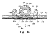
- the FIG. 1a shows a gear assembly 200 with a gear housing 202, of which only a partially sectioned gear housing shell 201 can be seen.
- a gear 203 is rotatably arranged in the gear housing 202.
- the gear 203 has a square socket 204 into which a control element can be inserted to drive the gear 203.
- the gear 203 has in the illustrated embodiment teeth 205, 207 at the end of the toothing, which are shorter than the teeth 206.
- the teeth 205, 207 adjacent teeth 206a are narrower than the teeth 206.
- the distance between the teeth 205, 207 and the adjacent teeth 206a is larger than that between the teeth 206.
- the teeth 205, 207 are formed asymmetrically.
- teeth 205, 206a, 206, 207 are provided.
- the teeth 205, 206, 206a, 207 are designed somewhat bulbous. This means that their tooth flanks are curved or bent.
- the teeth 212 with similar teeth 208, which taper towards the gear 3, is arranged on a coupling part 213, which is part of a drive rod 214.
- the drive rod 214 and in particular its coupling part 213 is arranged floating in the housing 202. This means that the drive rod 214 can move in the double arrow direction 215.
- a blocking contour 225a designed as a projection cooperates with a corresponding blocking contour 224a of the housing 2.
- a movement of the drive rod 214 in the drive rod movement direction 227 is thus blocked.
- the movement of the coupling part 213 in the upper position shown is favored by a spring element 232, which is supported on the housing 202.
- the gear 203 To the in the FIG. 1a To solve the back-up shown backup, the gear 203 must be rotated in a clockwise direction, as shown in the FIG. 1b is shown.
- the coupling part 213 By cooperation of the teeth 207, 206a of the gear 203 with the flanks of the teeth 208 of the coupling part 213, the coupling part 213 is displaced downward against the spring force of the spring element 232, so that the blocking contour 225a comes out of engagement with the locking contour 224a.
- the drive rod 214 which is part of an espagnolette fitting, displaced in the direction of arrow 226.
- the espagnolette fitting can be moved from a non-return unlocked position to a locking position.
- a loosening of the return lever is effected by a rotation of the gear 203 in the counterclockwise direction by cooperation of the teeth 205, 206, 206 a and 208.
Landscapes
- Engineering & Computer Science (AREA)
- Mechanical Engineering (AREA)
- Lock And Its Accessories (AREA)
- Power-Operated Mechanisms For Wings (AREA)
Abstract
Description
- Die Erfindung betrifft eine Getriebeanordnung für einen Treibstangenbeschlag eines Fensters, einer Tür oder dgl. mit einem Getriebegehäuse, in dem ein durch ein Bedienelement betätigbares Zahnrad angeordnet ist, dessen Zähne mit einer Zahnung eines Koppelteils kämmen, wobei das Koppelteil mit einer Treibstange des Treibstangenbeschlags gekoppelt ist und bei einer Betätigung des Zahnrads in Treibstangenbewegungsrichtung bewegbar ist, mit den Merkmalen des Oberbegriffs des Anspruchs 1.
- Ein Treibstangenbeschlag soll üblicherweise nur über ein Bedienelement aus einer Verriegelungsstellung in eine Öffnungsstellung bzw. Entriegelungsstellung bewegt werden können. Durch direkten Zugriff zur Treibstange oder zu einem daran befestigten Verriegelungselement kann ein Treibstangenbeschlag aber häufig durch Unbefugte aus der Verriegelungsstellung in die Öffnungsstellung gebracht werden, falls keine ihn in der Verriegelungsstellung sichernde Sperrvorrichtung bzw. Rückdrücksicherung vorgesehen ist. Eine Einbruchssicherung ist somit häufig nicht gegeben. Dies gestaltet sich besonders problematisch bei Fenstern, Türen oder dgl., die nach außen öffnende Flügel aufweisen, wie dies häufig in skandinavischen Ländern der Fall ist. Außerdem kann es wünschenswert sein, einen Treibstangenbeschlag in einer Entriegelungsstellung festzulegen, so dass er nicht durch eine an der Treibstange eingebrachte Kraft verstellbar ist.
- Aus der europäischen Patentanmeldung
2 581 531 A1 ist es bekannt, bei einem Getriebe für einen Treibstangenbeschlag eines Fensters, einer Tür oder dgl., mit einem Ritzel zum Antrieb einer Treibstange, sowie einem quer zur Treibstangenbewegungsrichtung bewegbaren Sperrelement, das in einer Verriegelungsstellung des Getriebes mit einer Sperrkontur derart zusammenwirkt, dass eine Treibstangenbewegung verhindert wird, ein mittels des Ritzels bei einer Bewegung aus der Verriegelungsstellung heraus bewegbares Löseelement vorzusehen, das einen Entsperrabschnitt aufweist, mit dem das Sperrelement in eine Freigabestellung verbringbar ist. - Ein solches Getriebe ist relativ aufwändig aufzubauen.
- Aufgabe der vorliegenden Erfindung ist es demgegenüber, eine vereinfachte und zuverlässig arbeitende, insbesondere ohne oder nur mit geringem Leerhub arbeitende Getriebeanordnung bereit zu stellen, mit der ein unbefugtes Verstellen eines Treibstangenbeschlags verhindert wird.
- Gelöst wird diese Aufgabe erfindungsgemäß durch eine Getriebeanordnung für einen Treibstangenbeschlag eines Fensters, einer Tür od. dgl., mit den Merkmalen des Anspruchs 1. Die Treibstangenbewegungsrichtung ist dabei die Richtung, in der sich die Treibstange erstreckt und in der sie zum Entriegeln und Verriegeln bewegt wird.
- Dabei ist das Koppelteil vorzugsweise so in dem Getriebegehäuse angeordnet, dass zum Ende einer Bewegung des Treibstangenbeschlags in eine Verriegelungsstellung das Koppelteil quer zur Treibstangenbewegungsrichtung bewegbar ist, so dass die Sperrkonturen zueinander in Eingriff gelangen. Wenn die Sperrkonturen des Koppelteils und des Gehäuses aneinander anliegen, wird eine Bewegung des Treibstangenbeschlags in Entriegelungsrichtung blockiert, die nicht durch das Zahnrad eingeleitet wird. Ein unbefugtes Öffnen des Treibstangenbeschlags ist somit nicht möglich. Wird dagegen das Zahnrad so betätigt, dass das Koppelteil in eine Entriegelungsrichtung des Treibstangenbeschlags bewegt wird, wird das Koppelteil erfindungsgemäß gleichzeitig zumindest zu Beginn der Entriegelungsbewegung auch quer zur Treibstangenbewegungsrichtung bewegt, so dass die Sperrkontur des Koppelteils außer Eingriff mit der Sperrkontur des Gehäuses gelangt. Dabei kann die erfindungsgemäße Getriebeanordnung so ausgebildet sein, dass kein oder ein nicht spürbarer Leerhub entsteht.
- Alternativ oder zusätzlich kann vorgesehen sein, dass Sperrkonturen des Koppelteils und des Gehäuses gegen Ende einer Entriegelungsbewegung in Eingriff gelangen und das Koppelteil quer zur Treibstangenbewegungsrichtung bewegt wird. Wird dann das Zahnrad so betätigt, dass das Koppelteil in eine Verriegelungsrichtung des Treibstangenbeschlags bewegt wird, wird das Koppelteil gleichzeitig zumindest zu Beginn der Verriegelungsbewegung auch quer zur Treibstangenbewegungsrichtung bewegt, so dass die Sperrkontur des Koppelteils außer Eingriff mit der Sperrkontur des Gehäuses gelangt.
- Vorzugsweise sind die Zähne des Zahnrads und die Zähne des Koppelteils so ausgebildet, dass sie sich jeweils zum Ende hin verjüngen.
- Eine zuverlässige Funktionsweise der Getriebeanordnung ergibt sich, wenn das Koppelteil in dem Getriebegehäuse geführt ist.
- Die Funktionssicherheit kann weiterhin dadurch erhöht werden, dass sich das Koppelteil über zumindest ein Federelement an dem Gehäuse oder der Treibstange abstützt. Wenn es sich bei dem Koppelteil jedoch um ein separates Teil handelt, welches nicht Bestandteil der Treibstange ist, ist ein Federelement nicht zwingend notwendig. Die Funktionssicherheit ist auch ohne Federelement gewährleistet. Insbesondere können in einer Verriegelungsstellung die Sperrkonturen selbsttätig in Eingriff gelangen. Dies kann hör- oder spürbar sein, so dass hiermit auch ein Verriegelungsindikator realisiert wird.
- Das Koppelteil kann einen Koppelvorsprung aufweisen, mit dem es formschlüssig mit der Treibstange gekoppelt ist. Insbesondere kann die Treibstange eine Öffnung aufweisen, die an die Form des Koppelvorsprungs angepasst ist. Beispielsweise kann die Treibstange ein Langloch aufweisen. Der Koppelvorsprung kann mit geringem Spiel in der Öffnung der Treibstange angeordnet sein.
- Weitere Vorteile ergeben sich, wenn die Sperrkontur des Koppelteils in einer Rückdrücksicherungsstellung des Treibstangenbeschlags flächig an der Sperrkontur des Gehäuses anliegt. Durch eine flächige Anlage wird zuverlässig ein unbefugtes Bewegen des Treibstangenbeschlags verhindert. Durch eine flächige Anlage erhöht sich die Stabilität. Insbesondere kann die Sperrkontur des Kopfteils zwei Flächen aufweisen, die einen spitzen Winkel zueinander bilden. Die Sperrkontur kann somit keilartig ausgebildet sein. Weiterhin kann die Sperrkontur bzgl. einer Mittenlängsebene auf zwei gegenüberliegenden Seiten des Koppelteils vorgesehen sein bzw. können zwei Sperrkonturen vorgesehen sein.
- Gemäß einer weiteren Ausführungsform kann vorgesehen sein, dass das Koppelteil Bestandteil der Treibstange ist. Dadurch kann die Anzahl der separaten Bauteile reduziert werden.
- Die Treibstange ist schwimmend im Gehäuse gelagert. Insbesondere kann die Treibstange dadurch quer zur Treibstangenbewegungsrichtung im Gehäuse bewegt werden. Dadurch kann eine Sperrkontur, die an der Treibstange angeordnet ist, in Eingriff mit einer entsprechenden Öffnung des Gehäuses gebracht werden.
- In den Rahmen der Erfindung fällt außerdem ein Fenster, eine Tür od. dgl. mit einer erfindungsgemäßen Getriebeanordnung.
- Weitere Merkmale und Vorteile der Erfindung ergeben sich aus der nachfolgenden Beschreibung von Ausführungsbeispielen der Erfindung, anhand der Figuren der Zeichnung, die erfindungswesentliche Einzelheiten zeigen und aus den Ansprüchen. Die einzelnen Merkmale können je einzeln für sich oder zu mehreren in beliebiger Kombination bei einer Variante der Erfindung verwirklicht sein.
- Bevorzugte Ausführungsbeispiele der Erfindung sind in der Zeichnung schematisch dargestellt und werden nachfolgend mit Bezug zu den Figuren der Zeichnung näher erläutert. Es zeigen:
- Fig. 1a bis
- eine Ausführungsform einer Getriebeanordnung
- Fig. 1e
- in unterschiedlichen Stadien der Benutzung.
- Die
Figur 1a zeigt eine Getriebeanordnung 200 mit einem Getriebegehäuse 202, von dem nur eine teilweise im Schnitt dargestellte Getriebegehäuseschale 201 zu sehen ist. In dem Getriebegehäuse 202 ist ein Zahnrad 203 drehbar angeordnet. Das Zahnrad 203 weist einen Innenvierkant 204 auf, in den ein Bedienelement eingesteckt werden kann, um das Zahnrad 203 anzutreiben. Das Zahnrad 203 weist im gezeigten Ausführungsbeispiel Zähne 205, 207 am Ende der Verzahnung auf, die kürzer sind als die Zähne 206. Die den Zähnen 205, 207 benachbarten Zähne 206a sind schmaler als die Zähne 206. Der Abstand zwischen den Zähnen 205, 207 und den benachbarten Zähnen 206a ist größer als der zwischen den Zähnen 206. Die Zähne 205, 207 sind unsymmetrisch ausgebildet. - Insgesamt sind etwa über die Hälfte des Umfangs des Zahnrads 203 Zähne 205, 206a, 206, 207 vorgesehen. Die Zähne 205, 206, 206a, 207 sind etwas bauchig ausgestaltet. Dies bedeutet, dass ihre Zahnflanken gewölbt oder gebogen sind. Die Zahnung 212 mit gleichartigen Zähnen 208, die sich zum Zahnrad 3 hin verjüngen, ist an einem Koppelteil 213 angeordnet, welches Bestandteil einer Treibstange 214 ist. Die Treibstange 214 und insbesondere deren Koppelteil 213 ist schwimmend im Gehäuse 202 angeordnet. Dies bedeutet, dass sich die Treibstange 214 in Doppelpfeilrichtung 215 bewegen kann. Dadurch, dass die Zähne 205, 207 kürzer sind als die übrigen Zähne 206, 206a, ist es möglich, dass sich das Koppelteil 213 in der gezeigten Endstellung des Zahnrads 203 etwas nach oben bewegt. Dies führt dazu, dass eine als Vorsprung ausgebildete Sperrkontur 225a mit einer entsprechenden Sperrkontur 224a des Gehäuses 2 zusammenwirkt. Eine Bewegung der Treibstange 214 in Treibstangenbewegungsrichtung 227 wird somit blockiert. Die Bewegung des Koppelteils 213 in die gezeigte obere Stellung wird durch ein Federelement 232 begünstigt, welches sich am Gehäuse 202 abstützt.
- Um die in der
Figur 1a gezeigte Rückdrücksicherung zu lösen, muss das Zahnrad 203 im Uhrzeigersinn gedreht werden, wie dies in derFigur 1b gezeigt ist. Durch Zusammenwirken der Zähne 207, 206a des Zahnrads 203 mit den Flanken der Zähne 208 des Koppelteils 213 wird das Koppelteil 213 gegen die Federkraft des Federelements 232 nach unten verlagert, so dass die Sperrkontur 225a außer Eingriff mit der Sperrkontur 224a gelangt. Bei einer weiteren Bewegung des Zahnrads 203 im Uhrzeigersinn wird die Treibstange 214, die Bestandteil eines Treibstangenbeschlags ist, in Pfeilrichtung 226 verlagert. Somit kann der Treibstangenbeschlag aus einer rückdrückgesicherten Entriegelungsstellung in eine Verriegelungsstellung bewegt werden. - Wie sich der
Figur 1c entnehmen lässt, wird die Treibstange 214 und insbesondere das Koppelteil 213 während der Verlagerung der Treibstange 214, die durch das Zahnrad 203 initiiert ist, durch das Zahnrad 203 in einer unteren Stellung gehalten. - In der in der
Figur 1d gezeigten Stellung befindet sich der Treibstangenbeschlag beinahe in der derFigur 1a entgegengesetzten Endstellung. Die Sperrkontur 225b gelangt, wenn das Zahnrad 203 etwas weiter gedreht wird, hinter die Fläche 223, so dass die Sperrkontur 225b nach oben bewegt werden kann und in Eingriff mit der Sperrkontur 224b gelangt. Die Zähne 205, 206a, 206 und 208 sind so aufeinander abgestimmt, dass eine Bewegung der Treibstange 214 bzw. des Koppelteils 213 quer zur Treibstangenbewegungsrichtung 227 möglich ist. - In der
Figur 1e ist die Situation gezeigt, in der sich der Treibstangenbeschlag in einer verriegelten Stellung befindet und eine Rückdrücksicherung aktiviert ist, da die Sperrkontur 225b in Eingriff mit der Sperrkontur 224b steht. - Ein Lösen der Rückdrücksicherung erfolgt durch eine Drehung des Zahnrads 203 entgegen dem Uhrzeigersinn durch Zusammenwirken der Zähne 205, 206, 206a und 208.
Claims (7)
- Getriebeanordnung (200) für einen Treibstangenbeschlag eines Fensters, einer Tür oder dgl. mit einem Getriebegehäuse (202), in dem ein durch ein Bedienelement betätigbares Zahnrad (203) angeordnet ist, dessen Zähne (205, 206, 207, 206a) mit der Zahnung (212) eines Koppelteils (213) kämmen, wobei das Koppelteil (213) mit einer Treibstange (214) des Treibstangenbeschlags gekoppelt ist und bei einer Betätigung des Zahnrads (203) in Treibstangenbewegungsrichtung (227) bewegbar ist, wobei das Koppelteil (213) eine Sperrkontur (225a, 225b) aufweist, mit der es in einer Verriegelungsstellung des Treibstangenbeschlags mit einer Sperrkontur (224a, 224b) des Getriebegehäuses (202) zusammen wirkt und derart im Gehäuse (202) angeordnet ist, dass es bei einer Betätigung des Zahnrads (203) zum Entriegeln oder Verriegeln des Treibstangenbeschlags eine Bewegung quer zur Treibstangenbewegungsrichtung (227) ausführt, dadurch gekennzeichnet, dass die Treibstange (214) schwimmend im Gehäuse (202) gelagert ist.
- Getriebeanordnung nach Anspruch 1, dadurch gekennzeichnet, dass das Koppelteil (213) in dem Getriebegehäuse (202) geführt ist.
- Getriebeanordnung nach einem der vorhergehenden Ansprüche,
dadurch gekennzeichnet, dass sich das Koppelteil (213) über zumindest ein Federelement (232) an dem Gehäuse (203) oder der Treibstange (214) abstützt. - Getriebeanordnung nach einem der vorhergehenden Ansprüche,
dadurch gekennzeichnet, dass das Koppelteil einen Koppelvorvorsprung aufweist, mit dem es formschlüssig mit der Treibstange gekoppelt ist. - Getriebeanordnung nach einem der vorhergehenden Ansprüche, dadurch gekennzeichnet, dass die Sperrkontur (225, 225a, 225b) des Koppelteils (213) in einer Rückdrücksicherungsstellung des Treibstangenbeschlags flächig an der Sperrkontur des Gehäuses (202) anliegt.
- Getriebeanordnung nach einem der vorhergehenden Ansprüche, dadurch gekennzeichnet, dass das Koppelteil (213) Bestandteil der Treibstange (214) ist.
- Fenster, Tür oder dgl. mit einer Getriebeanordnung (200) nach einem der vorhergehenden Ansprüche.
Priority Applications (2)
| Application Number | Priority Date | Filing Date | Title |
|---|---|---|---|
| EP14177749.0A EP2808466B1 (de) | 2013-03-26 | 2013-03-26 | Getriebeanordnung für einen Treibstangenbeschlag |
| PL14177749T PL2808466T3 (pl) | 2013-03-26 | 2013-03-26 | Układ przekładni dla okucia zasuwnicowego |
Applications Claiming Priority (2)
| Application Number | Priority Date | Filing Date | Title |
|---|---|---|---|
| EP13161024.8A EP2784248B1 (de) | 2013-03-26 | 2013-03-26 | Getriebeanordnung für einen Treibstangenbeschlag |
| EP14177749.0A EP2808466B1 (de) | 2013-03-26 | 2013-03-26 | Getriebeanordnung für einen Treibstangenbeschlag |
Related Parent Applications (2)
| Application Number | Title | Priority Date | Filing Date |
|---|---|---|---|
| EP13161024.8A Division-Into EP2784248B1 (de) | 2013-03-26 | 2013-03-26 | Getriebeanordnung für einen Treibstangenbeschlag |
| EP13161024.8A Division EP2784248B1 (de) | 2013-03-26 | 2013-03-26 | Getriebeanordnung für einen Treibstangenbeschlag |
Publications (3)
| Publication Number | Publication Date |
|---|---|
| EP2808466A2 true EP2808466A2 (de) | 2014-12-03 |
| EP2808466A3 EP2808466A3 (de) | 2015-04-01 |
| EP2808466B1 EP2808466B1 (de) | 2016-09-21 |
Family
ID=47998253
Family Applications (2)
| Application Number | Title | Priority Date | Filing Date |
|---|---|---|---|
| EP14177749.0A Active EP2808466B1 (de) | 2013-03-26 | 2013-03-26 | Getriebeanordnung für einen Treibstangenbeschlag |
| EP13161024.8A Active EP2784248B1 (de) | 2013-03-26 | 2013-03-26 | Getriebeanordnung für einen Treibstangenbeschlag |
Family Applications After (1)
| Application Number | Title | Priority Date | Filing Date |
|---|---|---|---|
| EP13161024.8A Active EP2784248B1 (de) | 2013-03-26 | 2013-03-26 | Getriebeanordnung für einen Treibstangenbeschlag |
Country Status (3)
| Country | Link |
|---|---|
| EP (2) | EP2808466B1 (de) |
| PL (2) | PL2784248T3 (de) |
| RU (1) | RU2664204C2 (de) |
Cited By (1)
| Publication number | Priority date | Publication date | Assignee | Title |
|---|---|---|---|---|
| CN108138524A (zh) * | 2015-08-21 | 2018-06-08 | 马科技术有限责任公司 | 用于窗户、门以及类似物的装配组件的传动装置 |
Families Citing this family (3)
| Publication number | Priority date | Publication date | Assignee | Title |
|---|---|---|---|---|
| CN112064546B (zh) * | 2020-08-27 | 2021-08-06 | 广东鸿彰建设工程有限公司 | 一种用于交通事故双向提示的环保型市政道路安全护栏 |
| HRP20221461T1 (hr) | 2020-11-09 | 2023-11-10 | Giesse S.P.A. | Operativni uređaj za vrata i prozore |
| DE102023205345A1 (de) | 2023-06-07 | 2024-12-12 | Roto Frank Fenster- und Türtechnologie GmbH | Getriebe mit Rückdrucksicherung |
Citations (1)
| Publication number | Priority date | Publication date | Assignee | Title |
|---|---|---|---|---|
| EP2581531A1 (de) | 2011-10-14 | 2013-04-17 | Roto Frank AG | Getriebe für einen Treibstangenbeschlag eines Fensters, einer Tür oder dergleichen |
Family Cites Families (4)
| Publication number | Priority date | Publication date | Assignee | Title |
|---|---|---|---|---|
| DE3034764C2 (de) * | 1980-09-15 | 1982-10-21 | Gretsch-Unitas Gmbh Baubeschlagfabrik, 7257 Ditzingen | Betätigungsvorrichtung für Treibstangenbeschläge |
| DE3335730A1 (de) * | 1983-10-01 | 1985-04-11 | Karl Fliether GmbH & Co, 5620 Velbert | Treibstangenschloss |
| FR2930582B1 (fr) * | 2008-04-23 | 2010-06-04 | Adler Sas | Dispositif de verrouillage de porte a cremone |
| GB2475507A (en) * | 2009-11-20 | 2011-05-25 | Rajnikant Mistry | Adjustable window espagnolette mechanism |
-
2013
- 2013-03-26 EP EP14177749.0A patent/EP2808466B1/de active Active
- 2013-03-26 PL PL13161024T patent/PL2784248T3/pl unknown
- 2013-03-26 EP EP13161024.8A patent/EP2784248B1/de active Active
- 2013-03-26 PL PL14177749T patent/PL2808466T3/pl unknown
-
2014
- 2014-03-25 RU RU2014111452A patent/RU2664204C2/ru not_active IP Right Cessation
Patent Citations (1)
| Publication number | Priority date | Publication date | Assignee | Title |
|---|---|---|---|---|
| EP2581531A1 (de) | 2011-10-14 | 2013-04-17 | Roto Frank AG | Getriebe für einen Treibstangenbeschlag eines Fensters, einer Tür oder dergleichen |
Cited By (2)
| Publication number | Priority date | Publication date | Assignee | Title |
|---|---|---|---|---|
| CN108138524A (zh) * | 2015-08-21 | 2018-06-08 | 马科技术有限责任公司 | 用于窗户、门以及类似物的装配组件的传动装置 |
| CN108138524B (zh) * | 2015-08-21 | 2020-03-20 | 马科技术有限责任公司 | 用于窗户、门以及类似物的装配组件的传动装置 |
Also Published As
| Publication number | Publication date |
|---|---|
| EP2784248B1 (de) | 2015-10-21 |
| EP2784248A1 (de) | 2014-10-01 |
| EP2808466A3 (de) | 2015-04-01 |
| RU2664204C2 (ru) | 2018-08-15 |
| PL2784248T3 (pl) | 2016-03-31 |
| EP2808466B1 (de) | 2016-09-21 |
| PL2808466T3 (pl) | 2017-02-28 |
| RU2014111452A (ru) | 2015-09-27 |
Similar Documents
| Publication | Publication Date | Title |
|---|---|---|
| EP2342405B1 (de) | Kraftfahrzeugschloss | |
| EP1178171B1 (de) | Kraftfahrzeugtürverschluss | |
| DE102006059568B4 (de) | Schließanlage für Türen, Fenster oder dergleichen, insbesondere Treibstangenschloss mit Panikfunktion und Mehrpunktverriegelung | |
| EP2581531A1 (de) | Getriebe für einen Treibstangenbeschlag eines Fensters, einer Tür oder dergleichen | |
| EP0007395B1 (de) | Türschloss mit schlüsselbetätigbarem Schliesszylinder | |
| DE1678121C3 (de) | VerschluBgehäuse mit Drehfalle und an dieser angreifenden Sperrklinke eines Kfz-Türverschlusses | |
| EP2808466B1 (de) | Getriebeanordnung für einen Treibstangenbeschlag | |
| DE102018007926A1 (de) | Schließbügel für ein Schloss, insbesondere für ein Türschloss, eines Kraftfahrzeugs sowie Schloss, insbesondere Türschloss, für ein Kraftfahrzeug | |
| DE4303400C2 (de) | Treibstangenschloss mit Abdicht- und Sicherheitsfunktion ß | |
| EP3406829B1 (de) | Türbeschlag für einen paniktürverschluss und paniktürverschluss | |
| DE102013200156A1 (de) | Beschlaganordnung | |
| DE102012111881A1 (de) | Motorisch betreibbares Standflügelschloss mit Riegel- und Fallenauswerfer | |
| EP2339096A2 (de) | Treibstangenschloss mit Panikfunktion und Mehrfachverriegelung | |
| WO2019063755A1 (de) | Kraftfahrzeugschloss | |
| WO2013010203A1 (de) | Schloss, insbesondere einsteckschloss | |
| WO2021205251A1 (de) | Kraftfahrzeug-schloss | |
| DE102012107145A1 (de) | Kraftfahrzeugtürverschluss | |
| EP2060714A2 (de) | Treibstangenschloss | |
| EP3963151B1 (de) | Verschluss mit einem verstärkten gehäuse für ein fenster, eine tür oder dergleichen | |
| WO2015000458A1 (de) | Kraftfahrzeugschloss mit positionssicherung | |
| AT413043B (de) | Zylinderbetätigbares mehrriegelschloss | |
| DE10010809A1 (de) | Kraftfahrzeug-Türschloß | |
| EP3266960A1 (de) | Anordnung mit einem blendrahmen zur lagerung eines flügelrahmens | |
| DE1204091B (de) | Mit Zuendschloss versehene Diebstahlsicherungsvorrichtung fuer Kraftfahrzeuge | |
| DE102024203222B3 (de) | Beschlaganordnung für ein Fenster, eine Tür oder dergleichen zur Betätigung einer Feststellbremse |
Legal Events
| Date | Code | Title | Description |
|---|---|---|---|
| PUAI | Public reference made under article 153(3) epc to a published international application that has entered the european phase |
Free format text: ORIGINAL CODE: 0009012 |
|
| 17P | Request for examination filed |
Effective date: 20140721 |
|
| AC | Divisional application: reference to earlier application |
Ref document number: 2784248 Country of ref document: EP Kind code of ref document: P |
|
| AK | Designated contracting states |
Kind code of ref document: A2 Designated state(s): AL AT BE BG CH CY CZ DE DK EE ES FI FR GB GR HR HU IE IS IT LI LT LU LV MC MK MT NL NO PL PT RO RS SE SI SK SM TR |
|
| AX | Request for extension of the european patent |
Extension state: BA ME |
|
| PUAL | Search report despatched |
Free format text: ORIGINAL CODE: 0009013 |
|
| AK | Designated contracting states |
Kind code of ref document: A3 Designated state(s): AL AT BE BG CH CY CZ DE DK EE ES FI FR GB GR HR HU IE IS IT LI LT LU LV MC MK MT NL NO PL PT RO RS SE SI SK SM TR |
|
| AX | Request for extension of the european patent |
Extension state: BA ME |
|
| RIC1 | Information provided on ipc code assigned before grant |
Ipc: E05B 17/20 20060101AFI20150223BHEP Ipc: E05C 9/02 20060101ALI20150223BHEP Ipc: E05B 15/04 20060101ALI20150223BHEP |
|
| R17P | Request for examination filed (corrected) |
Effective date: 20150327 |
|
| RBV | Designated contracting states (corrected) |
Designated state(s): AL AT BE BG CH CY CZ DE DK EE ES FI FR GB GR HR HU IE IS IT LI LT LU LV MC MK MT NL NO PL PT RO RS SE SI SK SM TR |
|
| GRAP | Despatch of communication of intention to grant a patent |
Free format text: ORIGINAL CODE: EPIDOSNIGR1 |
|
| INTG | Intention to grant announced |
Effective date: 20160525 |
|
| GRAS | Grant fee paid |
Free format text: ORIGINAL CODE: EPIDOSNIGR3 |
|
| GRAA | (expected) grant |
Free format text: ORIGINAL CODE: 0009210 |
|
| AC | Divisional application: reference to earlier application |
Ref document number: 2784248 Country of ref document: EP Kind code of ref document: P |
|
| AK | Designated contracting states |
Kind code of ref document: B1 Designated state(s): AL AT BE BG CH CY CZ DE DK EE ES FI FR GB GR HR HU IE IS IT LI LT LU LV MC MK MT NL NO PL PT RO RS SE SI SK SM TR |
|
| REG | Reference to a national code |
Ref country code: GB Ref legal event code: FG4D Free format text: NOT ENGLISH |
|
| REG | Reference to a national code |
Ref country code: CH Ref legal event code: EP |
|
| REG | Reference to a national code |
Ref country code: AT Ref legal event code: REF Ref document number: 831207 Country of ref document: AT Kind code of ref document: T Effective date: 20161015 |
|
| REG | Reference to a national code |
Ref country code: IE Ref legal event code: FG4D Free format text: LANGUAGE OF EP DOCUMENT: GERMAN |
|
| REG | Reference to a national code |
Ref country code: DE Ref legal event code: R096 Ref document number: 502013004734 Country of ref document: DE |
|
| REG | Reference to a national code |
Ref country code: LT Ref legal event code: MG4D Ref country code: NL Ref legal event code: MP Effective date: 20160921 |
|
| PG25 | Lapsed in a contracting state [announced via postgrant information from national office to epo] |
Ref country code: LT Free format text: LAPSE BECAUSE OF FAILURE TO SUBMIT A TRANSLATION OF THE DESCRIPTION OR TO PAY THE FEE WITHIN THE PRESCRIBED TIME-LIMIT Effective date: 20160921 Ref country code: FI Free format text: LAPSE BECAUSE OF FAILURE TO SUBMIT A TRANSLATION OF THE DESCRIPTION OR TO PAY THE FEE WITHIN THE PRESCRIBED TIME-LIMIT Effective date: 20160921 Ref country code: RS Free format text: LAPSE BECAUSE OF FAILURE TO SUBMIT A TRANSLATION OF THE DESCRIPTION OR TO PAY THE FEE WITHIN THE PRESCRIBED TIME-LIMIT Effective date: 20160921 Ref country code: NO Free format text: LAPSE BECAUSE OF FAILURE TO SUBMIT A TRANSLATION OF THE DESCRIPTION OR TO PAY THE FEE WITHIN THE PRESCRIBED TIME-LIMIT Effective date: 20161221 |
|
| PG25 | Lapsed in a contracting state [announced via postgrant information from national office to epo] |
Ref country code: GR Free format text: LAPSE BECAUSE OF FAILURE TO SUBMIT A TRANSLATION OF THE DESCRIPTION OR TO PAY THE FEE WITHIN THE PRESCRIBED TIME-LIMIT Effective date: 20161222 Ref country code: SE Free format text: LAPSE BECAUSE OF FAILURE TO SUBMIT A TRANSLATION OF THE DESCRIPTION OR TO PAY THE FEE WITHIN THE PRESCRIBED TIME-LIMIT Effective date: 20160921 Ref country code: NL Free format text: LAPSE BECAUSE OF FAILURE TO SUBMIT A TRANSLATION OF THE DESCRIPTION OR TO PAY THE FEE WITHIN THE PRESCRIBED TIME-LIMIT Effective date: 20160921 Ref country code: LV Free format text: LAPSE BECAUSE OF FAILURE TO SUBMIT A TRANSLATION OF THE DESCRIPTION OR TO PAY THE FEE WITHIN THE PRESCRIBED TIME-LIMIT Effective date: 20160921 |
|
| PG25 | Lapsed in a contracting state [announced via postgrant information from national office to epo] |
Ref country code: EE Free format text: LAPSE BECAUSE OF FAILURE TO SUBMIT A TRANSLATION OF THE DESCRIPTION OR TO PAY THE FEE WITHIN THE PRESCRIBED TIME-LIMIT Effective date: 20160921 Ref country code: RO Free format text: LAPSE BECAUSE OF FAILURE TO SUBMIT A TRANSLATION OF THE DESCRIPTION OR TO PAY THE FEE WITHIN THE PRESCRIBED TIME-LIMIT Effective date: 20160921 |
|
| PGFP | Annual fee paid to national office [announced via postgrant information from national office to epo] |
Ref country code: CH Payment date: 20170327 Year of fee payment: 5 |
|
| PG25 | Lapsed in a contracting state [announced via postgrant information from national office to epo] |
Ref country code: ES Free format text: LAPSE BECAUSE OF FAILURE TO SUBMIT A TRANSLATION OF THE DESCRIPTION OR TO PAY THE FEE WITHIN THE PRESCRIBED TIME-LIMIT Effective date: 20160921 Ref country code: CZ Free format text: LAPSE BECAUSE OF FAILURE TO SUBMIT A TRANSLATION OF THE DESCRIPTION OR TO PAY THE FEE WITHIN THE PRESCRIBED TIME-LIMIT Effective date: 20160921 Ref country code: BG Free format text: LAPSE BECAUSE OF FAILURE TO SUBMIT A TRANSLATION OF THE DESCRIPTION OR TO PAY THE FEE WITHIN THE PRESCRIBED TIME-LIMIT Effective date: 20161221 Ref country code: SM Free format text: LAPSE BECAUSE OF FAILURE TO SUBMIT A TRANSLATION OF THE DESCRIPTION OR TO PAY THE FEE WITHIN THE PRESCRIBED TIME-LIMIT Effective date: 20160921 Ref country code: IS Free format text: LAPSE BECAUSE OF FAILURE TO SUBMIT A TRANSLATION OF THE DESCRIPTION OR TO PAY THE FEE WITHIN THE PRESCRIBED TIME-LIMIT Effective date: 20170121 Ref country code: PT Free format text: LAPSE BECAUSE OF FAILURE TO SUBMIT A TRANSLATION OF THE DESCRIPTION OR TO PAY THE FEE WITHIN THE PRESCRIBED TIME-LIMIT Effective date: 20170123 Ref country code: SK Free format text: LAPSE BECAUSE OF FAILURE TO SUBMIT A TRANSLATION OF THE DESCRIPTION OR TO PAY THE FEE WITHIN THE PRESCRIBED TIME-LIMIT Effective date: 20160921 |
|
| REG | Reference to a national code |
Ref country code: DE Ref legal event code: R097 Ref document number: 502013004734 Country of ref document: DE |
|
| PG25 | Lapsed in a contracting state [announced via postgrant information from national office to epo] |
Ref country code: IT Free format text: LAPSE BECAUSE OF FAILURE TO SUBMIT A TRANSLATION OF THE DESCRIPTION OR TO PAY THE FEE WITHIN THE PRESCRIBED TIME-LIMIT Effective date: 20160921 |
|
| PLBE | No opposition filed within time limit |
Free format text: ORIGINAL CODE: 0009261 |
|
| STAA | Information on the status of an ep patent application or granted ep patent |
Free format text: STATUS: NO OPPOSITION FILED WITHIN TIME LIMIT |
|
| PG25 | Lapsed in a contracting state [announced via postgrant information from national office to epo] |
Ref country code: DK Free format text: LAPSE BECAUSE OF FAILURE TO SUBMIT A TRANSLATION OF THE DESCRIPTION OR TO PAY THE FEE WITHIN THE PRESCRIBED TIME-LIMIT Effective date: 20160921 |
|
| 26N | No opposition filed |
Effective date: 20170622 |
|
| GBPC | Gb: european patent ceased through non-payment of renewal fee |
Effective date: 20170326 |
|
| PG25 | Lapsed in a contracting state [announced via postgrant information from national office to epo] |
Ref country code: SI Free format text: LAPSE BECAUSE OF FAILURE TO SUBMIT A TRANSLATION OF THE DESCRIPTION OR TO PAY THE FEE WITHIN THE PRESCRIBED TIME-LIMIT Effective date: 20160921 Ref country code: MC Free format text: LAPSE BECAUSE OF FAILURE TO SUBMIT A TRANSLATION OF THE DESCRIPTION OR TO PAY THE FEE WITHIN THE PRESCRIBED TIME-LIMIT Effective date: 20160921 |
|
| REG | Reference to a national code |
Ref country code: IE Ref legal event code: MM4A |
|
| REG | Reference to a national code |
Ref country code: FR Ref legal event code: ST Effective date: 20171130 |
|
| PG25 | Lapsed in a contracting state [announced via postgrant information from national office to epo] |
Ref country code: LU Free format text: LAPSE BECAUSE OF NON-PAYMENT OF DUE FEES Effective date: 20170326 Ref country code: FR Free format text: LAPSE BECAUSE OF NON-PAYMENT OF DUE FEES Effective date: 20170331 |
|
| PG25 | Lapsed in a contracting state [announced via postgrant information from national office to epo] |
Ref country code: GB Free format text: LAPSE BECAUSE OF NON-PAYMENT OF DUE FEES Effective date: 20170326 Ref country code: IE Free format text: LAPSE BECAUSE OF NON-PAYMENT OF DUE FEES Effective date: 20170326 |
|
| REG | Reference to a national code |
Ref country code: BE Ref legal event code: MM Effective date: 20170331 |
|
| PG25 | Lapsed in a contracting state [announced via postgrant information from national office to epo] |
Ref country code: BE Free format text: LAPSE BECAUSE OF NON-PAYMENT OF DUE FEES Effective date: 20170331 |
|
| PG25 | Lapsed in a contracting state [announced via postgrant information from national office to epo] |
Ref country code: MT Free format text: LAPSE BECAUSE OF FAILURE TO SUBMIT A TRANSLATION OF THE DESCRIPTION OR TO PAY THE FEE WITHIN THE PRESCRIBED TIME-LIMIT Effective date: 20160921 |
|
| PG25 | Lapsed in a contracting state [announced via postgrant information from national office to epo] |
Ref country code: AL Free format text: LAPSE BECAUSE OF FAILURE TO SUBMIT A TRANSLATION OF THE DESCRIPTION OR TO PAY THE FEE WITHIN THE PRESCRIBED TIME-LIMIT Effective date: 20160921 |
|
| REG | Reference to a national code |
Ref country code: CH Ref legal event code: PL |
|
| PG25 | Lapsed in a contracting state [announced via postgrant information from national office to epo] |
Ref country code: CH Free format text: LAPSE BECAUSE OF NON-PAYMENT OF DUE FEES Effective date: 20180331 Ref country code: LI Free format text: LAPSE BECAUSE OF NON-PAYMENT OF DUE FEES Effective date: 20180331 |
|
| PG25 | Lapsed in a contracting state [announced via postgrant information from national office to epo] |
Ref country code: HU Free format text: LAPSE BECAUSE OF FAILURE TO SUBMIT A TRANSLATION OF THE DESCRIPTION OR TO PAY THE FEE WITHIN THE PRESCRIBED TIME-LIMIT; INVALID AB INITIO Effective date: 20130326 |
|
| PG25 | Lapsed in a contracting state [announced via postgrant information from national office to epo] |
Ref country code: CY Free format text: LAPSE BECAUSE OF FAILURE TO SUBMIT A TRANSLATION OF THE DESCRIPTION OR TO PAY THE FEE WITHIN THE PRESCRIBED TIME-LIMIT Effective date: 20160921 |
|
| PG25 | Lapsed in a contracting state [announced via postgrant information from national office to epo] |
Ref country code: MK Free format text: LAPSE BECAUSE OF FAILURE TO SUBMIT A TRANSLATION OF THE DESCRIPTION OR TO PAY THE FEE WITHIN THE PRESCRIBED TIME-LIMIT Effective date: 20160921 |
|
| PGFP | Annual fee paid to national office [announced via postgrant information from national office to epo] |
Ref country code: PL Payment date: 20200221 Year of fee payment: 8 Ref country code: AT Payment date: 20200319 Year of fee payment: 8 |
|
| PG25 | Lapsed in a contracting state [announced via postgrant information from national office to epo] |
Ref country code: HR Free format text: LAPSE BECAUSE OF FAILURE TO SUBMIT A TRANSLATION OF THE DESCRIPTION OR TO PAY THE FEE WITHIN THE PRESCRIBED TIME-LIMIT Effective date: 20160921 |
|
| PGFP | Annual fee paid to national office [announced via postgrant information from national office to epo] |
Ref country code: TR Payment date: 20200323 Year of fee payment: 8 |
|
| REG | Reference to a national code |
Ref country code: AT Ref legal event code: MM01 Ref document number: 831207 Country of ref document: AT Kind code of ref document: T Effective date: 20210326 |
|
| PG25 | Lapsed in a contracting state [announced via postgrant information from national office to epo] |
Ref country code: AT Free format text: LAPSE BECAUSE OF NON-PAYMENT OF DUE FEES Effective date: 20210326 |
|
| PG25 | Lapsed in a contracting state [announced via postgrant information from national office to epo] |
Ref country code: PL Free format text: LAPSE BECAUSE OF NON-PAYMENT OF DUE FEES Effective date: 20210326 |
|
| PGFP | Annual fee paid to national office [announced via postgrant information from national office to epo] |
Ref country code: DE Payment date: 20260320 Year of fee payment: 14 |