EP2808523A1 - Steuervorrichtung für einen verbrennungsmotor - Google Patents
Steuervorrichtung für einen verbrennungsmotor Download PDFInfo
- Publication number
- EP2808523A1 EP2808523A1 EP13740662.5A EP13740662A EP2808523A1 EP 2808523 A1 EP2808523 A1 EP 2808523A1 EP 13740662 A EP13740662 A EP 13740662A EP 2808523 A1 EP2808523 A1 EP 2808523A1
- Authority
- EP
- European Patent Office
- Prior art keywords
- torque
- internal combustion
- combustion engine
- ignition
- margin
- Prior art date
- Legal status (The legal status is an assumption and is not a legal conclusion. Google has not performed a legal analysis and makes no representation as to the accuracy of the status listed.)
- Withdrawn
Links
- 238000002485 combustion reaction Methods 0.000 title claims abstract description 111
- 230000007423 decrease Effects 0.000 claims abstract description 27
- 238000012937 correction Methods 0.000 claims description 44
- 230000001965 increasing effect Effects 0.000 claims description 11
- 230000003247 decreasing effect Effects 0.000 claims description 4
- 230000000979 retarding effect Effects 0.000 claims 1
- 239000000446 fuel Substances 0.000 abstract description 18
- 238000010586 diagram Methods 0.000 description 6
- 238000000034 method Methods 0.000 description 6
- 230000003197 catalytic effect Effects 0.000 description 5
- 230000000052 comparative effect Effects 0.000 description 4
- 238000002347 injection Methods 0.000 description 4
- 239000007924 injection Substances 0.000 description 4
- 238000011144 upstream manufacturing Methods 0.000 description 2
- 230000001276 controlling effect Effects 0.000 description 1
- 239000002826 coolant Substances 0.000 description 1
- 230000002708 enhancing effect Effects 0.000 description 1
- 230000001105 regulatory effect Effects 0.000 description 1
- 230000003584 silencer Effects 0.000 description 1
Images




Classifications
-
- F—MECHANICAL ENGINEERING; LIGHTING; HEATING; WEAPONS; BLASTING
- F02—COMBUSTION ENGINES; HOT-GAS OR COMBUSTION-PRODUCT ENGINE PLANTS
- F02P—IGNITION, OTHER THAN COMPRESSION IGNITION, FOR INTERNAL-COMBUSTION ENGINES; TESTING OF IGNITION TIMING IN COMPRESSION-IGNITION ENGINES
- F02P5/00—Advancing or retarding ignition; Control therefor
- F02P5/04—Advancing or retarding ignition; Control therefor automatically, as a function of the working conditions of the engine or vehicle or of the atmospheric conditions
- F02P5/145—Advancing or retarding ignition; Control therefor automatically, as a function of the working conditions of the engine or vehicle or of the atmospheric conditions using electrical means
-
- F—MECHANICAL ENGINEERING; LIGHTING; HEATING; WEAPONS; BLASTING
- F02—COMBUSTION ENGINES; HOT-GAS OR COMBUSTION-PRODUCT ENGINE PLANTS
- F02D—CONTROLLING COMBUSTION ENGINES
- F02D41/00—Electrical control of supply of combustible mixture or its constituents
- F02D41/02—Circuit arrangements for generating control signals
- F02D41/04—Introducing corrections for particular operating conditions
- F02D41/08—Introducing corrections for particular operating conditions for idling
- F02D41/083—Introducing corrections for particular operating conditions for idling taking into account engine load variation, e.g. air-conditionning
-
- F—MECHANICAL ENGINEERING; LIGHTING; HEATING; WEAPONS; BLASTING
- F02—COMBUSTION ENGINES; HOT-GAS OR COMBUSTION-PRODUCT ENGINE PLANTS
- F02P—IGNITION, OTHER THAN COMPRESSION IGNITION, FOR INTERNAL-COMBUSTION ENGINES; TESTING OF IGNITION TIMING IN COMPRESSION-IGNITION ENGINES
- F02P5/00—Advancing or retarding ignition; Control therefor
- F02P5/04—Advancing or retarding ignition; Control therefor automatically, as a function of the working conditions of the engine or vehicle or of the atmospheric conditions
- F02P5/145—Advancing or retarding ignition; Control therefor automatically, as a function of the working conditions of the engine or vehicle or of the atmospheric conditions using electrical means
- F02P5/15—Digital data processing
- F02P5/1502—Digital data processing using one central computing unit
- F02P5/1508—Digital data processing using one central computing unit with particular means during idling
-
- Y—GENERAL TAGGING OF NEW TECHNOLOGICAL DEVELOPMENTS; GENERAL TAGGING OF CROSS-SECTIONAL TECHNOLOGIES SPANNING OVER SEVERAL SECTIONS OF THE IPC; TECHNICAL SUBJECTS COVERED BY FORMER USPC CROSS-REFERENCE ART COLLECTIONS [XRACs] AND DIGESTS
- Y02—TECHNOLOGIES OR APPLICATIONS FOR MITIGATION OR ADAPTATION AGAINST CLIMATE CHANGE
- Y02T—CLIMATE CHANGE MITIGATION TECHNOLOGIES RELATED TO TRANSPORTATION
- Y02T10/00—Road transport of goods or passengers
- Y02T10/10—Internal combustion engine [ICE] based vehicles
- Y02T10/40—Engine management systems
Definitions
- the present invention relates to an internal combustion engine control device configured to suppress rotation fluctuations occurring owing to load changes during idling operation.
- An engine which is mounted on a vehicle as a driving power source, also serves as a driving power source for auxiliary machines, such as a compressor of an air conditioner, an oil pump of a power steering, and the like.
- auxiliary machines such as a compressor of an air conditioner, an oil pump of a power steering, and the like.
- an intake air quantity may be controlled according to the load fluctuations such that the output torque of the internal combustion engine changes.
- a certain response delay occurs until a change in throttle opening emerges as a change in the quantity of air with which the combustion chamber is filled. Therefore, it is impossible to compensate for output torque fluctuations of the internal combustion engine, occurring owing to the load fluctuations of the internal combustion engine, with a better response by intake-air-quantity control.
- the influence of the load fluctuations of the internal combustion engine on the output torque of the internal combustion engine becomes relatively great.
- Patent document 1 teaches an internal combustion engine that, at idling operation during which the output torque of the internal combustion engine becomes small, ignition timing is shifted to an ignition-timing change side on which the output (the efficiency) is decreased, while supplying an intake air quantity exceeding a given quantity corresponding to an actual output torque, so as to cope with the load fluctuations of the internal combustion engine by ignition-timing adjustment. That is, a predetermined margin torque is preset as a torque that can be increased only by ignition-timing adjustment. Hence, when the load of the internal combustion engine has fluctuated during idling operation, it is possible to change the output torque of the internal combustion engine with a better response only by ignition-timing adjustment.
- the margin torque is set to increase, when the load of the internal combustion engine is high during idling operation.
- the load acting on the internal combustion engine during idling operation tends to increase, when the auxiliary machines and the like come into operation.
- the load during idling operation is high, it is considered that many auxiliary machines are in their active states.
- the load during idling operation is low, it is considered that many auxiliary machines are in their inactive states. That is, in the case that the load of the internal combustion engine during idling operation is high, it is considered that the total auxiliary load of auxiliary machines which may possibly act on the internal combustion engine tends to decrease from such a high-load condition. Conversely in the case that the load of the internal combustion engine during idling operation is low, it is considered that the total auxiliary load of auxiliary machines which may possibly act on the internal combustion engine tends to increase from such a low-load condition.
- Patent document 1 Japanese Unexamined Patent Application Publication (Translation of PCT Application) No. 1998-503259
- the invention is characterized in that, in an internal combustion engine control device in which a predetermined margin torque is set such that it is possible to maintain a predetermined engine idling speed by adjusting ignition timing, the margin torque is set to decrease, as a load of the internal combustion engine increases.
- the margin torque can be set to an appropriate value, and thus it is possible to improve the fuel economy performance during idling operation of the internal combustion engine.
- FIG. 1 shows the schematic system configuration of an internal combustion engine 1 to which the invention can be applied.
- an intake passage 4 is connected through an intake valve 3 to a combustion chamber 2 of internal combustion engine 1, whereas an exhaust passage 6 is connected through an exhaust valve 5 to the combustion chamber.
- a spark plug 7 is centrally located at the top of the combustion chamber 2.
- a fuel injection valve 8 is also located on the side face of combustion chamber 2 and arranged on the side of intake valve 3, for directly injecting fuel into the combustion chamber 2.
- Fuel which has been adjusted or regulated to a predetermined pressure level by a high-pressure fuel pump (not shown) or the like, is supplied through a high-pressure fuel passage 9 into the fuel injection valve 8.
- An airflow meter 10 which detects an intake air quantity, is located in the intake passage 4.
- a throttle valve 11 is located downstream of the airflow meter 10.
- Throttle valve 11 is equipped with an actuator 11a, which is comprised of an electric motor.
- the throttle opening of throttle valve 11 is controlled responsively to a control signal given or outputted from an engine control unit (ECU) 12.
- ECU engine control unit
- the valve opening of throttle 11 i.e., the throttle opening
- the throttle opening is controlled based on a signal detected by the throttle-valve opening sensor 11b, such that the valve opening of throttle valve 11 is brought closer to a target opening.
- a catalytic converter 13, a second catalytic converter 14, and an exhaust silencer (a muffler) 15 are arranged in that order from the upstream side of exhaust passage 6. Also, an air-fuel (A/F) ratio sensor 16, which detects an air-fuel ratio, is located upstream of the catalytic converter 13.
- A/F air-fuel
- EGR exhaust-gas-recirculation passage 17 through which part of exhaust gas is recirculated or sent back to an intake system, is provided between the intake passage 4 and the exhaust passage 6.
- One end of EGR passage 17 is connected to the intake passage 4 at the downstream side of throttle valve 11, whereas the other end is connected to the exhaust passage 6 between the catalytic converter 13 and the second catalytic converter 14.
- the recirculation amount of exhaust gas, flowing through the EGR passage 17, is adjusted by an EGR control valve 18.
- a temperature of exhaust gas (EGR gas), flowing through the EGR passage 17, is detected by an EGR temperature sensor 19.
- ECU 12 receives sensor signals detected by a variety of sensors, such as a crank angle sensor 20 that detects an engine revolution speed (engine speed) and a crank angle position, an accelerator opening sensor 22 that detects a depression amount (an accelerator opening) of a driver-operated accelerator pedal 21, a vehicle speed sensor 23 that detects vehicle speed, and the like.
- sensors such as a crank angle sensor 20 that detects an engine revolution speed (engine speed) and a crank angle position, an accelerator opening sensor 22 that detects a depression amount (an accelerator opening) of a driver-operated accelerator pedal 21, a vehicle speed sensor 23 that detects vehicle speed, and the like.
- ECU 12 controls, based on these input signals detected by various sensors, a fuel injection amount, fuel injection timing, throttle opening, valve opening of EGR control valve 18, and the like.
- an air-conditioner compressor, a radiator fan, an alternator serving as a generator for charging a vehicle-mounted battery, a power-steering oil pump and the like are also driven by the internal combustion engine 1. That is, when these auxiliary machines, i.e., the air conditioner, the radiator, the alternator, the power-steering oil pump and the like, are driven responsively to a drive request for driving each auxiliary machine, auxiliary loads act on the internal combustion engine 1. Thus, a load of internal combustion engine 1 fluctuates (increases).
- a predetermined margin torque is set to prevent rotation fluctuations from occurring owing to load fluctuations by compensating or correcting such a delay in the output-torque increase produced by the increase in the intake air quantity by ignition-timing adjustment.
- ignition timing is retarded from the minimum advance for the best torque (MBT) at this operating point by a predetermined ignition-timing correction amount.
- MBT best torque
- a torque decrease caused by the retarded ignition timing by increasing the intake air quantity and by totally ensuring the output torque needed for the idling operation at the certain operating point, it is possible to set a torque, whose magnitude corresponds to the torque decrease caused by the retarded ignition timing, in other words, a margin torque that can be increased only by ignition-timing adjustment.
- the margin torque is a torque that can be increased only by ignition-timing adjustment such that ignition timing is shifted to an ignition-timing change side (an ignition-timing retard side) on which the output (the efficiency) is decreased, while supplying an intake air quantity exceeding a given quantity corresponding to an actual output torque.
- this internal combustion engine is put into a state where it is possible to suppress the occurrence of rotation fluctuations by advancing the ignition timing under this condition and by increasing the output torque with a better response and consequently compensating a delay in the output-torque increase produced by an increase in the intake air quantity.
- the margin torque has to cope with each and every load containing auxiliary loads which may possibly act on the internal combustion engine 1. Therefore, under an operating condition in which the load of the internal combustion engine during idling operation is low, for instance, under a specific condition in which all of the auxiliary machines are in their inactive states, it is necessary to cope with each and every auxiliary load, and necessarily the margin torque has to be set a high value. Conversely under an condition in which the load of the internal combustion engine during idling operation is high, for instance, under a specific condition in which all of the auxiliary machines are in their active states, it is not necessary to cope with a further auxiliary load. Hence, the margin torque can be set to such small value as to absorb hunting of idling speeds in a steady state.
- the margin torque is set to decrease, as the load of internal combustion engine 1 during idling operation increases. This is because ignition timing tends to retard from the minimum advance for the best torque (MBT), as the margin torque becomes set higher. Hence, suppose that the margin torque has been set excessively higher than required. As a matter of course, owing to such excessive margin torque setting, the fuel economy performance tends to deteriorate.
- a charging efficiency is used as a parameter indicating the magnitude of load acting on internal combustion engine 1, and also a margin torque is arithmetically calculated by the use of a margin-torque calculation map that the margin torque is calculated based on a charging efficiency.
- the charging efficiency is calculated based on a detected value of airflow meter 10 by means of ECU 12.
- the above-mentioned margin-torque calculation map is predetermined or prepared in advance via experimental conformity evaluated by real machine tests, such that a margin torque is set to increase, as a charging efficiency decreases.
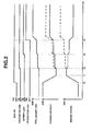
- Fig. 2 is the timing chart illustrating a change in charging efficiency and a change in margin torque in the first embodiment.
- the broken line indicates a comparative example in which a margin torque is set to increase, as the load acting on internal combustion engine 1 during idling operation increases.
- a margin torque whose magnitude is sufficient to cope with all loads which may possibly simultaneously act on the internal combustion engine 1 during the idling operation, is set.
- the margin torque and the charging efficiency both change in a manner so as to be brought closer to their desired values at each individual predetermined rate of change from the time t0, taking account of the driveability, without changing in a stepwise manner at the time t0.
- the margin torque gradually increases from the time t0 when the operating condition becomes shifted to idling operation, and then reaches a desired value at the current operating point at the time t1.
- the charging efficiency gradually decreases from the time t0 when the operating condition becomes shifted to idling operation, and then reaches a desired value at the current operating point at the time t1.
- a radiator-fan load caused by the radiator fan driven from the time t2 acts on the internal combustion engine 1.
- a battery load caused by the alternator driven from the time t3, acts on the internal combustion engine 1.
- an air-conditioner load caused by the air-conditioner compressor driven from the time t4, acts on the internal combustion engine 1.
- the margin torque is set to decrease, as the load of internal combustion engine 1 during idling operation increases.
- the margin torque tends to decrease in a stepwise manner at each of the times t2, t3, and t4.
- the margin torque is set to decrease as the load of internal combustion engine 1 during idling operation increases, it is possible to relatively decrease the charging efficiency, when compared to the comparative example in which the margin torque is set to increase as the load of internal combustion engine 1 during idling operation increases. Hence, it is possible to relatively enhance the fuel economy performance during idling operation.
- the margin torque can be set to an appropriate value by setting the margin torque lower as the load of the internal combustion engine becomes higher. Hence, it is possible to enhance the fuel economy performance during idling operation of the internal combustion engine.
- a charging efficiency is used as a parameter indicating operating conditions of auxiliary machines, and thus it is possible to easily calculate auxiliary-machines operating conditions.
- the intake air quantity increases as the engine revolution speed increases, and thus rotation fluctuations tend to reduce, because of more stable combustion. Accordingly, it is possible to bring the margin torque to a more appropriate value by setting the margin torque lower as the engine revolution speed increases.
- Fig. 3 is the block diagram illustrating procedures of arithmetic calculation for a target throttle opening and a target ignition timing during idling operation in the first embodiment.
- a margin torque is calculated by the use of a first margin-torque calculation map, prepared in advance via experimental conformity, and a charging efficiency.
- the first margin-torque calculation map is set such that a margin torque increases, as a charging efficiency decreases.
- an output torque of internal combustion engine 1 (an MBT-ignition engine torque) when having been ignited at the minimum advance for the best torque (MBT) under the current operating condition, is calculated based on an MBT-ignition engine torque calculation map, prepared in advance via experimental conformity, a charging efficiency, and a current (latest up-to-date) engine revolution speed detected by the crank angle sensor 20.
- a torque-down rate is calculated by dividing the margin torque, calculated at step S11, by the MBT-ignition engine torque, calculated at step S12.
- step S14 an ignition-timing correction amount is calculated by the use of an ignition-timing correction amount calculation map, prepared in advance via experimental conformity, and the torque-down rate, calculated at step S13. That is, this step S14 corresponds to an ignition-timing correction amount calculation means.
- such an ignition-timing correction amount may be calculated directly from the margin torque.
- the ignition-timing correction amount from the ignition-timing correction calculation map that is a single map data in which there is a one-to-one correspondence between an ignition-timing correction amount and a torque-down rate.
- MBT best torque
- a base idle ignition timing is calculated by subtracting the ignition-timing correction amount, calculated at step S14, from the minimum advance for the best torque (MBT) for the current operating condition.
- a revolution-speed difference is calculated by subtracting the current engine revolution speed detected by the crank angle sensor 20 from a current target engine revolution speed.
- a torque correction rate at which the engine revolution speed is brought closer to the current target engine revolution speed, is calculated based on the revolution-speed difference, calculated at step S16.
- an ISC request ignition-timing correction amount which is based on an idle-speed-control (ISC) request needed to bring the engine revolution speed of internal combustion engine 1 closer to the target revolution speed, is calculated by the use of an ISC request ignition-timing correction amount calculation map, prepared in advance via experimental conformity, and the torque correction rate, calculated at step S17. That is, a series of steps S16-S18 are configured to calculate an amount of feedback correction (feedback compensation) of ignition timing when executing feedback control such that the engine revolution speed of internal combustion engine 1 is brought closer to the target revolution speed.
- a final ignition timing is calculated by adding the ISC request ignition-timing correction amount, calculated at step S18, to the base idle ignition timing, calculated at step S15.
- a required engine indicated torque which is required for the internal combustion engine 1 during idling operation.
- the required engine indicated torque is calculated by adding an auxiliary-machine drive-request torque needed to drive the auxiliary machines with their drive requests to an idle-speed-holding request torque needed to maintain or hold a predetermined engine idling speed, and further adding another request torque for devices (for example, a wiper device that comes into operation, a power window that comes into operation, and the like) that require an increase in the load of internal combustion engine 1 due to factors other than the above to the idle-speed-holding request torque.
- the required engine indicated torque can be comprehended or regarded as a desired value of the charging efficiency.
- auxiliary-machine drive-request torques there are an air-conditioner request torque corresponding to the previously-discussed air-conditioner load, a radiator-fan request torque corresponding to the radiator-fan load, a battery request torque corresponding to the battery (alternator) load, and a power-steering request torque corresponding to the power-steering oil pump drive request.
- a required margin torque is calculated by the use of a second margin-torque calculation map, prepared in advance via experimental conformity, and the required engine indicated torque, calculated at step S21.
- the second margin-torque calculation map is set such that a margin torque increases, as a required engine indicated torque decreases.
- an MBT-ignition required engine indicated torque (a required torque) is calculated by adding the required margin torque, calculated at step S22, to the required engine indicated torque, calculated at step S21.
- a target throttle opening is calculated by the use of a throttle opening calculation map, prepared in advance via experimental conformity, and the MBT-ignition required engine indicated torque (the required torque), calculated at step S23.
- the throttle opening calculation map is set such that a target throttle opening increases, as an MBT-ignition required engine indicated torque (a required torque) increases.
- the former is based on the required engine indicated torque (a desired value of the charging efficiency) corresponding to a required torque value (a target torque value) in which auxiliary-machine driving torques and the like are included.
- the latter is based on an actual charging efficiency calculated based on a detected value of airflow meter 10.
- the required engine indicated torque (a desired value of the charging efficiency) corresponding to a required torque value may be utilized as a margin torque used for calculating the ignition timing.
- the former margin-torque calculation map or the latter margin-torque calculation map may be selectively used, for instance, depending on a rate of change in throttle opening.
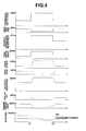
- Fig. 4 is the timing chart illustrating one example of changes in various parameters during idling operation in the first embodiment.
- the required engine indicated torque calculated at step S21
- the required margin torque calculated at step S22
- the MBT-ignition required engine indicated torque calculated at step S23
- the charging efficiency increases, because of an increase in the load acting on the internal combustion engine 1.
- the margin torque calculated at step S11, tends to decrease during the time period T1-T2 during which the auxiliary machine is operating.
- the MBT-ignition engine torque, calculated at step S12 increases, whereas the torque-down rate, calculated at step S13, decreases. Also, during the time period T1-T2, the ignition-timing correction amount (a retard amount), calculated at step S14, decreases.
- the ignition timing calculated at step S19, retards during the time period T1-T2.
- an increase in the intake air quantity can be suppressed by decreasing the margin torque during the time period T1-T2 during which the load of internal combustion engine 1 is increasing.
- the retard amount of ignition timing with respect to the minimum advance for the best torque (MBT) indicated by the broken line in Fig. 4 , tends to become relatively small.
- the margin torque is set to decrease, as the load of internal combustion engine 1 increases.
- the margin torque is calculated as a value obtained by subtracting the load, which has already acted on the internal combustion engine 1, from a summed value of all loads which may possibly act on the internal combustion engine 1 during idling operation.
- the second embodiment it is possible to more accurately set a necessary margin torque by exactly grasping a summed value of loads which may possibly act on the internal combustion engine 1 during idling operation.
- the second embodiment in the same manner as the first embodiment, it is possible to enhance the fuel economy performance during idling operation of the internal combustion engine.
- Fig. 5 is the block diagram illustrating procedures of arithmetic calculation for a target throttle opening and a target ignition timing during idling operation in the second embodiment.
- a required engine indicated torque which is required for the internal combustion engine 1 during idling operation, is calculated.
- the required engine indicated torque is calculated by adding the auxiliary-machine drive-request torque to the idle-speed-holding request torque, and further adding another request torque to the idle-speed-holding request torque.
- the margin torque is calculated as a value obtained by subtracting the load, which has already acted on the internal combustion engine 1, from a summed value of all auxiliary loads which may possibly act on the internal combustion engine 1 during idling operation.
- a target engine indicated torque (a required torque) is calculated by adding the margin torque, calculated at step S32, to the required engine indicated torque, calculated at step S31.
- a target throttle opening is calculated by the use of a throttle opening calculation map, prepared in advance via experimental conformity, and the target engine indicated torque (the required torque), calculated at step S33.
- the throttle opening calculation map is set such that a target throttle opening increases, as a target engine indicated torque (a required torque) increases.
- an output torque of internal combustion engine 1 (an MBT-ignition engine torque) when having been ignited at the minimum advance for the best torque (MBT) under the current operating condition, is calculated based on an MBT-ignition engine torque calculation map, prepared in advance via experimental conformity, a charging efficiency, and a current (latest up-to-date) engine revolution speed detected by the crank angle sensor 20.
- a torque-down rate is calculated by dividing the margin torque, calculated at step S32, by the MBT-ignition engine torque, calculated at step S41.
- an ignition-timing correction amount is calculated by the use of an ignition-timing correction amount calculation map, prepared in advance via experimental conformity, and the torque-down rate, calculated at step S42.
- a base idle ignition timing is calculated by subtracting the ignition-timing correction amount, calculated at step S43, from the minimum advance for the best torque (MBT) for the current operating condition.
- a revolution-speed difference is calculated by subtracting the current engine revolution speed detected by the crank angle sensor 20 from a current target engine revolution speed.
- a torque correction rate at which the engine revolution speed is brought closer to the current target engine revolution speed, is calculated based on the revolution-speed difference, calculated at step S45.
- an ISC request ignition-timing correction amount which is based on an idle-speed-control (ISC) request needed to bring the engine revolution speed of internal combustion engine 1 closer to the target revolution speed, is calculated by the use of an ISC request ignition-timing correction amount calculation map, prepared in advance via experimental conformity, and the torque correction rate, calculated at step S46.
- a final ignition timing is calculated by adding the ISC request ignition-timing correction amount, calculated at step S47, to the base idle ignition timing, calculated at step S44.
- the margin torque is set to decrease, as the load of internal combustion engine 1 increases.
- the margin torque is calculated only from a required engine indicated torque, which is required for the internal combustion engine 1 during idling operation.
- the third embodiment it is possible to calculate a margin torque by using a required engine indicated torque corresponding to a target torque value as a parameter indicating the magnitude of load, possibly acting on the internal combustion engine during idling operation, prior to feedback control for engine revolution speed, executed such that the engine revolution speed of internal combustion engine 1 is brought closer to a predetermined engine idling speed. Hence, it is possible to suppress an undesirable drop or a flare-up of engine revolution speed. Also, in the third embodiment, the margin torque is set to decrease, as the load of internal combustion engine 1 increases. Hence, in the third embodiment, in the same manner as the first embodiment, it is possible to enhance the fuel economy performance during idling operation of the internal combustion engine.
- Fig. 6 is the block diagram illustrating procedures of arithmetic calculation for a target throttle opening and a target ignition timing during idling operation in the third embodiment.
- a required engine indicated torque which is required for the internal combustion engine 1 during idling operation, is calculated.
- the required engine indicated torque is calculated by adding the auxiliary-machine drive-request torque to the idle-speed-holding request torque, and further adding another request torque to the idle-speed-holding request torque.
- a margin torque is calculated by the use of a margin-torque calculation map, prepared in advance via experimental conformity, and the required engine indicated torque, calculated at step S51.
- the margin-torque calculation map is set such that a margin torque increases, as a required engine indicated torque decreases.
- a target engine indicated torque (a required torque) is calculated by adding the margin torque, calculated at step S52, to the required engine indicated torque, calculated at step S31.
- a target throttle opening is calculated by the use of a throttle opening calculation map, prepared in advance via experimental conformity, and the target engine indicated torque (the required torque), calculated at step S53.
- the throttle opening calculation map is set such that a target throttle opening increases, as a target engine indicated torque (a required torque) increases.
- an output torque of internal combustion engine 1 (an MBT-ignition engine torque) when having been ignited at the minimum advance for the best torque (MBT) under the current operating condition, is calculated based on an MBT-ignition engine torque calculation map, prepared in advance via experimental conformity, a charging efficiency, and a current (latest up-to-date) engine revolution speed detected by the crank angle sensor 20.
- a torque-down rate is calculated by dividing the margin torque, calculated at step S52, by the MBT-ignition engine torque, calculated at step S61.
- an ignition-timing correction amount is calculated by the use of an ignition-timing correction amount calculation map, prepared in advance via experimental conformity, and the torque-down rate, calculated at step S62.
- a base idle ignition timing is calculated by subtracting the ignition-timing correction amount, calculated at step S63, from the minimum advance for the best torque (MBT) for the current operating condition.
- a revolution-speed difference is calculated by subtracting the current engine revolution speed detected by the crank angle sensor 20 from a current target engine revolution speed.
- a torque correction rate at which the engine revolution speed is brought closer to the current target engine revolution speed, is calculated based on the revolution-speed difference, calculated at step S65.
- an ISC request ignition-timing correction amount which is based on an idle-speed-control (ISC) request needed to bring the engine revolution speed of internal combustion engine 1 closer to the target revolution speed, is calculated by the use of an ISC request ignition-timing correction amount calculation map, prepared in advance via experimental conformity, and the torque correction rate, calculated at step S66.
- a final ignition timing is calculated by adding the ISC request ignition-timing correction amount, calculated at step S67, to the base idle ignition timing, calculated at step S64.
Landscapes
- Engineering & Computer Science (AREA)
- Chemical & Material Sciences (AREA)
- Combustion & Propulsion (AREA)
- Mechanical Engineering (AREA)
- General Engineering & Computer Science (AREA)
- Theoretical Computer Science (AREA)
- Signal Processing (AREA)
- Electrical Control Of Ignition Timing (AREA)
- Combined Controls Of Internal Combustion Engines (AREA)
- Electrical Control Of Air Or Fuel Supplied To Internal-Combustion Engine (AREA)
Applications Claiming Priority (2)
| Application Number | Priority Date | Filing Date | Title |
|---|---|---|---|
| JP2012012543A JP2013151892A (ja) | 2012-01-25 | 2012-01-25 | 内燃機関の制御装置 |
| PCT/JP2013/051322 WO2013111781A1 (ja) | 2012-01-25 | 2013-01-23 | 内燃機関の制御装置 |
Publications (2)
| Publication Number | Publication Date |
|---|---|
| EP2808523A1 true EP2808523A1 (de) | 2014-12-03 |
| EP2808523A4 EP2808523A4 (de) | 2015-10-14 |
Family
ID=48873496
Family Applications (1)
| Application Number | Title | Priority Date | Filing Date |
|---|---|---|---|
| EP13740662.5A Withdrawn EP2808523A4 (de) | 2012-01-25 | 2013-01-23 | Steuervorrichtung für einen verbrennungsmotor |
Country Status (5)
| Country | Link |
|---|---|
| US (1) | US9309858B2 (de) |
| EP (1) | EP2808523A4 (de) |
| JP (1) | JP2013151892A (de) |
| CN (1) | CN104364503A (de) |
| WO (1) | WO2013111781A1 (de) |
Families Citing this family (6)
| Publication number | Priority date | Publication date | Assignee | Title |
|---|---|---|---|---|
| JP6146367B2 (ja) * | 2014-04-11 | 2017-06-14 | トヨタ自動車株式会社 | エンジン回転速度制御装置 |
| KR101610722B1 (ko) * | 2014-12-15 | 2016-04-08 | 현대오트론 주식회사 | 엔진 토크 제어방법 및 그 장치 |
| DE102015006976A1 (de) * | 2015-06-01 | 2016-12-01 | Man Truck & Bus Ag | Magerbetrieb im Leerlauf zur Partikelzahlreduzierung |
| KR102261346B1 (ko) * | 2017-04-27 | 2021-06-07 | 현대자동차주식회사 | 토크 리저브 제어 방법 |
| CN113187642B (zh) * | 2021-04-26 | 2022-09-13 | 东风汽车集团股份有限公司 | 基于发动机燃空比请求的点火控制系统及方法 |
| CN119163511A (zh) * | 2024-09-11 | 2024-12-20 | 柳州柳工挖掘机有限公司 | 基于液压挖掘机的电控发动机控制方法及装置 |
Family Cites Families (24)
| Publication number | Priority date | Publication date | Assignee | Title |
|---|---|---|---|---|
| JPH04203250A (ja) * | 1990-11-29 | 1992-07-23 | Mitsubishi Motors Corp | 走行負荷分補償式速度制御部付ドライブバイワイヤ式車両 |
| JP3318945B2 (ja) * | 1992-03-02 | 2002-08-26 | 株式会社日立製作所 | 自動車用制御装置、自動車制御システム及び自動車の制御方法 |
| DE19517673A1 (de) | 1995-05-13 | 1996-11-14 | Bosch Gmbh Robert | Verfahren und Vorrichtung zur Steuerung des Drehmoments einer Brennkraftmaschine |
| JP3620148B2 (ja) * | 1996-06-14 | 2005-02-16 | 日産自動車株式会社 | エンジンの回転数制御装置 |
| JP3812111B2 (ja) * | 1997-12-19 | 2006-08-23 | 日産自動車株式会社 | 内燃機関の制御装置 |
| JP2002036867A (ja) * | 2000-07-31 | 2002-02-06 | Zexel Valeo Climate Control Corp | 空調制御装置 |
| JP2002276447A (ja) * | 2001-03-19 | 2002-09-25 | Denso Corp | 内燃機関の制御装置 |
| JP2003269306A (ja) * | 2002-03-13 | 2003-09-25 | Nissan Motor Co Ltd | エンジンの点火時期制御装置 |
| ITBO20030213A1 (it) | 2003-04-11 | 2004-10-12 | Magneti Marelli Powertrain Spa | Metodo per il controllo del regime di un motore |
| DE10324958B4 (de) | 2003-06-03 | 2017-02-02 | Robert Bosch Gmbh | Verfahren und Vorrichtung zum Betreiben einer Brennkraftmaschine eines Fahrzeugs |
| DE102004012522B3 (de) | 2004-03-16 | 2006-01-12 | Bayerische Motoren Werke Ag | Verfahren zur Steuerung einer Brennkraftmaschine |
| JP2006138300A (ja) * | 2004-11-15 | 2006-06-01 | Denso Corp | 内燃機関のトルク制御装置 |
| US7314033B2 (en) * | 2004-11-18 | 2008-01-01 | Massachusetts Institute Of Technology | Fuel management system for variable ethanol octane enhancement of gasoline engines |
| JP4483789B2 (ja) * | 2006-01-13 | 2010-06-16 | 日産自動車株式会社 | ハイブリッド車両の駆動装置 |
| JP4654173B2 (ja) * | 2006-11-16 | 2011-03-16 | 日立オートモティブシステムズ株式会社 | 車両の制御装置 |
| JP4407711B2 (ja) * | 2007-03-19 | 2010-02-03 | トヨタ自動車株式会社 | トルクディマンド型の内燃機関の制御装置 |
| JP4597156B2 (ja) * | 2007-03-19 | 2010-12-15 | トヨタ自動車株式会社 | トルクディマンド型の内燃機関の制御装置 |
| JP2009167991A (ja) * | 2008-01-21 | 2009-07-30 | Denso Corp | 内燃機関のアイドル運転制御装置 |
| JP5098911B2 (ja) * | 2008-09-09 | 2012-12-12 | トヨタ自動車株式会社 | 車載内燃機関の制御装置 |
| EP2351924B1 (de) * | 2008-10-31 | 2016-12-28 | Toyota Jidosha Kabushiki Kaisha | Steuerungsvorrichtung für einen verbrennungsmotor |
| JP4792516B2 (ja) * | 2009-07-07 | 2011-10-12 | 本田技研工業株式会社 | 内燃機関の制御装置 |
| JP5257624B2 (ja) * | 2010-06-07 | 2013-08-07 | 三菱自動車工業株式会社 | 車両の出力制御装置 |
| JP5293717B2 (ja) * | 2010-10-01 | 2013-09-18 | 三菱自動車工業株式会社 | エンジンの制御装置 |
| JP5287818B2 (ja) * | 2010-10-01 | 2013-09-11 | 三菱自動車工業株式会社 | エンジンの制御装置 |
-
2012
- 2012-01-25 JP JP2012012543A patent/JP2013151892A/ja active Pending
-
2013
- 2013-01-23 EP EP13740662.5A patent/EP2808523A4/de not_active Withdrawn
- 2013-01-23 CN CN201380006772.XA patent/CN104364503A/zh active Pending
- 2013-01-23 WO PCT/JP2013/051322 patent/WO2013111781A1/ja not_active Ceased
- 2013-01-23 US US14/364,084 patent/US9309858B2/en not_active Expired - Fee Related
Also Published As
| Publication number | Publication date |
|---|---|
| CN104364503A (zh) | 2015-02-18 |
| US20140360464A1 (en) | 2014-12-11 |
| WO2013111781A1 (ja) | 2013-08-01 |
| JP2013151892A (ja) | 2013-08-08 |
| EP2808523A4 (de) | 2015-10-14 |
| US9309858B2 (en) | 2016-04-12 |
Similar Documents
| Publication | Publication Date | Title |
|---|---|---|
| JP3627464B2 (ja) | エンジンの制御装置 | |
| JP2855952B2 (ja) | 内燃エンジンのアイドル回転数制御方法 | |
| US8676478B2 (en) | Engine stop control device | |
| KR101781719B1 (ko) | 내연 기관의 제어 장치 | |
| JP5939263B2 (ja) | 内燃機関の制御装置 | |
| US8332122B2 (en) | Control apparatus for vehicle drive unit | |
| US9309858B2 (en) | Internal combustion engine control device | |
| EP2565433A1 (de) | Steuerungsvorrichtung für einen verbrennungsmotor | |
| JPWO2012081111A1 (ja) | 内燃機関の制御装置 | |
| US11378035B2 (en) | Engine control device | |
| JP2010024963A (ja) | 内燃機関の制御装置 | |
| US8739762B2 (en) | Engine controlling apparatus | |
| US6240894B1 (en) | Control system for cylinder injection type internal combustion engine | |
| JP2016098786A (ja) | 内燃機関の制御装置 | |
| EP0615066A1 (de) | Steuerungsvorrichtung für eine mehrzylindrige innere brennkraftmaschine | |
| JP4457361B2 (ja) | 内燃機関の制御装置 | |
| JPH11148383A (ja) | 車両内燃機関の制御方法及び装置 | |
| JP2017180245A (ja) | エンジンの制御装置 | |
| JP5253239B2 (ja) | 内燃機関の制御装置 | |
| JP5326998B2 (ja) | 内燃機関の制御装置 | |
| JP2008095579A (ja) | 内燃機関制御装置 | |
| JP5585599B2 (ja) | エンジン制御装置 | |
| JP3325975B2 (ja) | エンジンの制御装置 | |
| JP2008280984A (ja) | 内燃機関の制御装置 | |
| JP2015117604A (ja) | 内燃機関の制御装置 |
Legal Events
| Date | Code | Title | Description |
|---|---|---|---|
| PUAI | Public reference made under article 153(3) epc to a published international application that has entered the european phase |
Free format text: ORIGINAL CODE: 0009012 |
|
| 17P | Request for examination filed |
Effective date: 20140822 |
|
| AK | Designated contracting states |
Kind code of ref document: A1 Designated state(s): AL AT BE BG CH CY CZ DE DK EE ES FI FR GB GR HR HU IE IS IT LI LT LU LV MC MK MT NL NO PL PT RO RS SE SI SK SM TR |
|
| DAX | Request for extension of the european patent (deleted) | ||
| RA4 | Supplementary search report drawn up and despatched (corrected) |
Effective date: 20150914 |
|
| RIC1 | Information provided on ipc code assigned before grant |
Ipc: F02D 29/00 20060101ALI20150908BHEP Ipc: F02P 5/15 20060101ALI20150908BHEP Ipc: F02D 45/00 20060101ALI20150908BHEP Ipc: F02D 41/08 20060101ALI20150908BHEP Ipc: F02D 41/16 20060101AFI20150908BHEP |
|
| STAA | Information on the status of an ep patent application or granted ep patent |
Free format text: STATUS: THE APPLICATION IS DEEMED TO BE WITHDRAWN |
|
| 18D | Application deemed to be withdrawn |
Effective date: 20160412 |