EP2808527A2 - Verfahren und Vorrichtung zum Betreiben einer Brennkraftmaschine - Google Patents
Verfahren und Vorrichtung zum Betreiben einer Brennkraftmaschine Download PDFInfo
- Publication number
- EP2808527A2 EP2808527A2 EP14000133.0A EP14000133A EP2808527A2 EP 2808527 A2 EP2808527 A2 EP 2808527A2 EP 14000133 A EP14000133 A EP 14000133A EP 2808527 A2 EP2808527 A2 EP 2808527A2
- Authority
- EP
- European Patent Office
- Prior art keywords
- heat
- engine
- internal combustion
- combustion engine
- exhaust
- Prior art date
- Legal status (The legal status is an assumption and is not a legal conclusion. Google has not performed a legal analysis and makes no representation as to the accuracy of the status listed.)
- Granted
Links
Images
Classifications
-
- F—MECHANICAL ENGINEERING; LIGHTING; HEATING; WEAPONS; BLASTING
- F01—MACHINES OR ENGINES IN GENERAL; ENGINE PLANTS IN GENERAL; STEAM ENGINES
- F01N—GAS-FLOW SILENCERS OR EXHAUST APPARATUS FOR MACHINES OR ENGINES IN GENERAL; GAS-FLOW SILENCERS OR EXHAUST APPARATUS FOR INTERNAL-COMBUSTION ENGINES
- F01N5/00—Exhaust or silencing apparatus combined or associated with devices profiting by exhaust energy
- F01N5/02—Exhaust or silencing apparatus combined or associated with devices profiting by exhaust energy the devices using heat
-
- F—MECHANICAL ENGINEERING; LIGHTING; HEATING; WEAPONS; BLASTING
- F01—MACHINES OR ENGINES IN GENERAL; ENGINE PLANTS IN GENERAL; STEAM ENGINES
- F01K—STEAM ENGINE PLANTS; STEAM ACCUMULATORS; ENGINE PLANTS NOT OTHERWISE PROVIDED FOR; ENGINES USING SPECIAL WORKING FLUIDS OR CYCLES
- F01K23/00—Plants characterised by more than one engine delivering power external to the plant, the engines being driven by different fluids
- F01K23/02—Plants characterised by more than one engine delivering power external to the plant, the engines being driven by different fluids the engine cycles being thermally coupled
- F01K23/06—Plants characterised by more than one engine delivering power external to the plant, the engines being driven by different fluids the engine cycles being thermally coupled combustion heat from one cycle heating the fluid in another cycle
- F01K23/065—Plants characterised by more than one engine delivering power external to the plant, the engines being driven by different fluids the engine cycles being thermally coupled combustion heat from one cycle heating the fluid in another cycle the combustion taking place in an internal combustion piston engine, e.g. a diesel engine
-
- F—MECHANICAL ENGINEERING; LIGHTING; HEATING; WEAPONS; BLASTING
- F01—MACHINES OR ENGINES IN GENERAL; ENGINE PLANTS IN GENERAL; STEAM ENGINES
- F01K—STEAM ENGINE PLANTS; STEAM ACCUMULATORS; ENGINE PLANTS NOT OTHERWISE PROVIDED FOR; ENGINES USING SPECIAL WORKING FLUIDS OR CYCLES
- F01K23/00—Plants characterised by more than one engine delivering power external to the plant, the engines being driven by different fluids
- F01K23/02—Plants characterised by more than one engine delivering power external to the plant, the engines being driven by different fluids the engine cycles being thermally coupled
- F01K23/06—Plants characterised by more than one engine delivering power external to the plant, the engines being driven by different fluids the engine cycles being thermally coupled combustion heat from one cycle heating the fluid in another cycle
- F01K23/10—Plants characterised by more than one engine delivering power external to the plant, the engines being driven by different fluids the engine cycles being thermally coupled combustion heat from one cycle heating the fluid in another cycle with exhaust fluid of one cycle heating the fluid in another cycle
-
- F—MECHANICAL ENGINEERING; LIGHTING; HEATING; WEAPONS; BLASTING
- F01—MACHINES OR ENGINES IN GENERAL; ENGINE PLANTS IN GENERAL; STEAM ENGINES
- F01K—STEAM ENGINE PLANTS; STEAM ACCUMULATORS; ENGINE PLANTS NOT OTHERWISE PROVIDED FOR; ENGINES USING SPECIAL WORKING FLUIDS OR CYCLES
- F01K23/00—Plants characterised by more than one engine delivering power external to the plant, the engines being driven by different fluids
- F01K23/12—Plants characterised by more than one engine delivering power external to the plant, the engines being driven by different fluids the engines being mechanically coupled
- F01K23/14—Plants characterised by more than one engine delivering power external to the plant, the engines being driven by different fluids the engines being mechanically coupled including at least one combustion engine
-
- F—MECHANICAL ENGINEERING; LIGHTING; HEATING; WEAPONS; BLASTING
- F01—MACHINES OR ENGINES IN GENERAL; ENGINE PLANTS IN GENERAL; STEAM ENGINES
- F01N—GAS-FLOW SILENCERS OR EXHAUST APPARATUS FOR MACHINES OR ENGINES IN GENERAL; GAS-FLOW SILENCERS OR EXHAUST APPARATUS FOR INTERNAL-COMBUSTION ENGINES
- F01N5/00—Exhaust or silencing apparatus combined or associated with devices profiting by exhaust energy
- F01N5/02—Exhaust or silencing apparatus combined or associated with devices profiting by exhaust energy the devices using heat
- F01N5/025—Exhaust or silencing apparatus combined or associated with devices profiting by exhaust energy the devices using heat the device being thermoelectric generators
-
- F—MECHANICAL ENGINEERING; LIGHTING; HEATING; WEAPONS; BLASTING
- F02—COMBUSTION ENGINES; HOT-GAS OR COMBUSTION-PRODUCT ENGINE PLANTS
- F02B—INTERNAL-COMBUSTION PISTON ENGINES; COMBUSTION ENGINES IN GENERAL
- F02B73/00—Combinations of two or more engines, not otherwise provided for
-
- F—MECHANICAL ENGINEERING; LIGHTING; HEATING; WEAPONS; BLASTING
- F02—COMBUSTION ENGINES; HOT-GAS OR COMBUSTION-PRODUCT ENGINE PLANTS
- F02G—HOT GAS OR COMBUSTION-PRODUCT POSITIVE-DISPLACEMENT ENGINE PLANTS; USE OF WASTE HEAT OF COMBUSTION ENGINES; NOT OTHERWISE PROVIDED FOR
- F02G1/00—Hot gas positive-displacement engine plants
- F02G1/04—Hot gas positive-displacement engine plants of closed-cycle type
- F02G1/043—Hot gas positive-displacement engine plants of closed-cycle type the engine being operated by expansion and contraction of a mass of working gas which is heated and cooled in one of a plurality of constantly communicating expansible chambers, e.g. Stirling cycle type engines
-
- F—MECHANICAL ENGINEERING; LIGHTING; HEATING; WEAPONS; BLASTING
- F02—COMBUSTION ENGINES; HOT-GAS OR COMBUSTION-PRODUCT ENGINE PLANTS
- F02G—HOT GAS OR COMBUSTION-PRODUCT POSITIVE-DISPLACEMENT ENGINE PLANTS; USE OF WASTE HEAT OF COMBUSTION ENGINES; NOT OTHERWISE PROVIDED FOR
- F02G5/00—Profiting from waste heat of combustion engines, not otherwise provided for
- F02G5/02—Profiting from waste heat of exhaust gases
-
- F—MECHANICAL ENGINEERING; LIGHTING; HEATING; WEAPONS; BLASTING
- F02—COMBUSTION ENGINES; HOT-GAS OR COMBUSTION-PRODUCT ENGINE PLANTS
- F02G—HOT GAS OR COMBUSTION-PRODUCT POSITIVE-DISPLACEMENT ENGINE PLANTS; USE OF WASTE HEAT OF COMBUSTION ENGINES; NOT OTHERWISE PROVIDED FOR
- F02G2254/00—Heat inputs
- F02G2254/15—Heat inputs by exhaust gas
-
- F—MECHANICAL ENGINEERING; LIGHTING; HEATING; WEAPONS; BLASTING
- F02—COMBUSTION ENGINES; HOT-GAS OR COMBUSTION-PRODUCT ENGINE PLANTS
- F02G—HOT GAS OR COMBUSTION-PRODUCT POSITIVE-DISPLACEMENT ENGINE PLANTS; USE OF WASTE HEAT OF COMBUSTION ENGINES; NOT OTHERWISE PROVIDED FOR
- F02G2260/00—Recuperating heat from exhaust gases of combustion engines and heat from cooling circuits
-
- F—MECHANICAL ENGINEERING; LIGHTING; HEATING; WEAPONS; BLASTING
- F02—COMBUSTION ENGINES; HOT-GAS OR COMBUSTION-PRODUCT ENGINE PLANTS
- F02G—HOT GAS OR COMBUSTION-PRODUCT POSITIVE-DISPLACEMENT ENGINE PLANTS; USE OF WASTE HEAT OF COMBUSTION ENGINES; NOT OTHERWISE PROVIDED FOR
- F02G2262/00—Recuperating heat from exhaust gases of combustion engines and heat from lubrication circuits
-
- F—MECHANICAL ENGINEERING; LIGHTING; HEATING; WEAPONS; BLASTING
- F02—COMBUSTION ENGINES; HOT-GAS OR COMBUSTION-PRODUCT ENGINE PLANTS
- F02G—HOT GAS OR COMBUSTION-PRODUCT POSITIVE-DISPLACEMENT ENGINE PLANTS; USE OF WASTE HEAT OF COMBUSTION ENGINES; NOT OTHERWISE PROVIDED FOR
- F02G2280/00—Output delivery
- F02G2280/20—Rotary generators
-
- F—MECHANICAL ENGINEERING; LIGHTING; HEATING; WEAPONS; BLASTING
- F02—COMBUSTION ENGINES; HOT-GAS OR COMBUSTION-PRODUCT ENGINE PLANTS
- F02G—HOT GAS OR COMBUSTION-PRODUCT POSITIVE-DISPLACEMENT ENGINE PLANTS; USE OF WASTE HEAT OF COMBUSTION ENGINES; NOT OTHERWISE PROVIDED FOR
- F02G2280/00—Output delivery
- F02G2280/70—Clutches
-
- Y—GENERAL TAGGING OF NEW TECHNOLOGICAL DEVELOPMENTS; GENERAL TAGGING OF CROSS-SECTIONAL TECHNOLOGIES SPANNING OVER SEVERAL SECTIONS OF THE IPC; TECHNICAL SUBJECTS COVERED BY FORMER USPC CROSS-REFERENCE ART COLLECTIONS [XRACs] AND DIGESTS
- Y02—TECHNOLOGIES OR APPLICATIONS FOR MITIGATION OR ADAPTATION AGAINST CLIMATE CHANGE
- Y02E—REDUCTION OF GREENHOUSE GAS [GHG] EMISSIONS, RELATED TO ENERGY GENERATION, TRANSMISSION OR DISTRIBUTION
- Y02E20/00—Combustion technologies with mitigation potential
- Y02E20/30—Technologies for a more efficient combustion or heat usage
-
- Y—GENERAL TAGGING OF NEW TECHNOLOGICAL DEVELOPMENTS; GENERAL TAGGING OF CROSS-SECTIONAL TECHNOLOGIES SPANNING OVER SEVERAL SECTIONS OF THE IPC; TECHNICAL SUBJECTS COVERED BY FORMER USPC CROSS-REFERENCE ART COLLECTIONS [XRACs] AND DIGESTS
- Y02—TECHNOLOGIES OR APPLICATIONS FOR MITIGATION OR ADAPTATION AGAINST CLIMATE CHANGE
- Y02T—CLIMATE CHANGE MITIGATION TECHNOLOGIES RELATED TO TRANSPORTATION
- Y02T10/00—Road transport of goods or passengers
- Y02T10/10—Internal combustion engine [ICE] based vehicles
- Y02T10/12—Improving ICE efficiencies
Definitions
- the present invention relates to a method for operating an internal combustion engine, to an apparatus for carrying out the method and to an internal combustion engine according to the invention.
- the object of the invention is to provide a method and an apparatus for carrying out the method and a method according to internal combustion engine, in particular for commercial vehicles, whose efficiency is raised by improved utilization of exhaust enthalpy.
- the exhaust gas enthalpy in the exhaust gas flow of the internal combustion engine is used to operate a heat engine, in particular a Stirling engine, which generates mechanical energy.
- a Stirling engine also referred to as a hot gas engine
- a heat engine which can be of a known type with a closed circuit and converts the heat into mechanical energy.
- a Stirling engine as a preferred heat engine.
- the term Stirling engine is here to be understood expressly in a comprehensive sense and is representative of any heat engine suitable for carrying out the method according to the invention, in which a working medium, in particular a working gas (for example air, helium or hydrogen). , heated and cooled to perform mechanical work.
- a working medium in particular a working gas (for example air, helium or hydrogen).
- the Stirling engine may be used to drive an electric machine (preferably a generator) and thus generate power; if necessary, the machine can also be switched as a starter.
- an electric machine preferably a generator
- the Stirling engine can be coupled with its drive shaft to the crankshaft of the internal combustion engine and thus control a superimposed drive torque, in particular in part-load and / or full load operation of the internal combustion engine.
- a speed controller while the speed of the drive shaft of the Stirling engine can be adjusted efficiency-optimized to the instantaneous speed of the crankshaft of the internal combustion engine.
- the exhaust gas enthalpy in the exhaust gas flow of the internal combustion engine as drive heat flow Q ZU to the Stirling engine either indirectly, in particular with the interposition of at least one insects Creekübertragers, or transmitted directly.
- at least one heat pipe preferably a plurality of heat pipes (for the sake of clarity, the plurality of "heat pipes" are used hereinafter) are used in an exhaust pipe of the internal combustion engine, the Stirling engine, preferably a working piston of the Stirling engine associated heat exchanger or heat transfer area, indirectly, in particular with interposition at least one insects enjoyedtragers, or directly with the drive heat flux Q ZU and thus acted upon by drive energy.
- an exhaust pipe may be branched off whose heat flow flows through the Stirling engine or a heat exchanger or heat transfer area of the Stirling engine.
- the heat pipes can particularly preferably be arranged upstream of the branch point of the exhaust gas for the exhaust gas recirculation device, so that a lower exhaust gas cooling is required by the associated decrease in temperature of the exhaust gas, which possibly even allows the elimination of an exhaust gas cooler in the return line.
- the heat pipes can be provided in a catalytic exhaust aftertreatment device in the exhaust system of the internal combustion engine upstream of the aftertreatment device, in particular so as to be able to derive a higher drive energy or a higher drive heat flow to the Stirling engine if necessary.
- a temperature control of the exhaust gas could be provided in the exhaust system, for example, at low exhaust gas temperatures (cold start) to bypass the heat pipes and preferably to apply the aftertreatment device.
- a particularly preferred device for carrying out the method on an internal combustion engine with a fuel-air supply device and a downstream exhaust system is that the exhaust system is coupled heat-transmitting to a heat engine or a Stirling engine via at least one heat pipe, in particular via a plurality of heat pipes integrated therein generating electrical and / or mechanical energy.
- the Stirling engine can thereby drive an electric machine and / or be coupled with its drive shaft with the crankshaft of the internal combustion engine.
- the heat sink of the Stirling engine can preferably be cooled by the wind of the motor vehicle and / or connected via a heat exchanger to the liquid cooling system of the internal combustion engine.
- an exhaust gas housing of the exhaust system in an internal combustion engine with exhaust aftertreatment device and / or exhaust gas recirculation the heat pipes for the Stirling engine, which is positioned upstream of the exhaust aftertreatment device and / or the exhaust gas recirculation return line.
- the exhaust aftertreatment device can be formed by an SCR catalyst.
- an internal combustion engine in particular for commercial vehicles, with the features listed above as well as a vehicle, in particular a commercial vehicle, is preferably proposed.
- a multi-cylinder reciprocating internal combustion engine or a diesel engine for a commercial vehicle which may not be described as conventional construction type and its crankshaft 2 abrades on the other drive means of the motor vehicle.
- the internal combustion engine 1 has an only indicated fuel-air supply device with an intake manifold 3 and the exhaust gases laxative exhaust system 4 as far as not described known type.
- an exhaust turbocharger with at least one exhaust gas turbine in the exhaust system 4 could be provided.
- a Stirling engine 6 is coupled, whose drive shaft 7 is connected on the one hand to the crankshaft 2 and on the other hand to an electric machine 8, for example an alternator. aborts.
- the Stirling engine 6 is exemplified in the exemplary embodiment as an alpha-type, with a working piston 9 and a displacer 10 whose 90 degrees offset from each other cylinder (not shown) in a known manner in a more or less closed gas circuit with each other, wherein in a known manner the Cylinder of the displacer 10 is designed as a heat sink (Q AB ) is cooled (only with the arrow 11 indicated), while the cylinder of the working piston 9 is heated by heat (Q ZU ).
- the Stirling engine 6 could also be designed in a known manner as a beta-type with coaxial cylinders or as a gamma type.
- the cooling Q AB is carried out either by wind, for example by arranging cooling fins on the cylinder of the displacer 10 and / or by liquid cooling with connection of the cylinder 10 and a corresponding heat exchanger to the cooling fluid system of the internal combustion engine 1, not shown.
- an exhaust aftertreatment device with an SCR catalyst 17 selective catalytic reduction
- Exhaust gas can be recycled in defined rates to the intake manifold 3 of the internal combustion engine 1 via the exhaust gas recirculation valve 16 and an exhaust gas recirculation line 18.
- an exhaust gas recirculation line 18 may be provided in the exhaust gas recirculation line 18 connected to the liquid cooling system of the internal combustion engine 1 exhaust gas cooler.
- the drive energy generated by the heat coupling can be directed to the crankshaft 2 and / or the electric machine 8 for power generation in the vehicle electrical system.
- the machine 8 can also be connected as an electric motor to serve as a starter motor or deliver additional drive energy in a boost mode.
- a controllable bypass line 19 (indicated by dashed lines) may be provided which cause a bypass of the heat pipes 15.
- a controllable bypass line 19 (indicated by dashed lines) may be provided which cause a bypass of the heat pipes 15.
Landscapes
- Engineering & Computer Science (AREA)
- Chemical & Material Sciences (AREA)
- Combustion & Propulsion (AREA)
- Mechanical Engineering (AREA)
- General Engineering & Computer Science (AREA)
- Exhaust-Gas Circulating Devices (AREA)
- Exhaust Gas After Treatment (AREA)
- Control Of Vehicle Engines Or Engines For Specific Uses (AREA)
Abstract
Description
- Die vorliegende Erfindung betrifft ein Verfahren zum Betreiben einer Brennkraftmaschine, eine Vorrichtung zur Durchführung des Verfahrens und eine verfahrensgemäße Brennkraftmaschine.
- Brennkraftmaschinen, insbesondere in Kraftfahrzeugen oder Nutzkraftfahrzeugen, sind häufig aus Wirkungsgradgründen als Dieselmotoren konzipiert und weisen zur Erfüllung von Umweltauflagen Abgasnachbehandlungseinrichtungen wie SCR Katalysatoren und/oder Abgasrückführeinrichtungen auf. Dabei kann die im Abgas der Brennkraftmaschine enthaltene Abgasenthalpie nicht optimal genutzt werden. Hohe Abgasrückführraten belasten zudem den Kühlkreislauf der Brennkraftmaschine der zumeist flüssigkeitsgekühlten Brennkraftmaschinen durch die notwendige Rückkühlung der Abgase über entsprechende Abgaskühler, gegebenenfalls in Verbindung mit zusätzlichen Niedertemperaturkreisläufen.
- Aufgabe der Erfindung ist es, ein Verfahren und eine Vorrichtung zur Durchführung des Verfahrens sowie eine verfahrensgemäße Brennkraftmaschine, insbesondere für Nutzkraftfahrzeuge anzugeben, deren Wirkungsgrad durch verbesserte Ausnutzung der Abgasenthalpie angehoben ist.
- Die Lösung dieser Aufgabe gelingt mit den Merkmalen der unabhängigen Patentansprüche. Vorteilhafte Weiterbildungen und Ausgestaltungen sind Gegenstand der Unteransprüche.
- Erfindungsgemäß wird vorgeschlagen, dass die Abgasenthalpie im Abgasstrom der Brennkraftmaschine zum Betreiben einer Wärmekraftmaschine, insbesondere eines Stirlingmotors, genutzt wird, die mechanische Energie erzeugt.
- Damit können im Wesentlichen zwei Vorteile erzielt werden, nämlich einerseits eine Nutzung der im Abgas enthaltenen Abwärme und andererseits stromab der Entnahmestelle der Wärme eine Absenkung der Abgastemperaturen, die gegebenenfalls den Wärmehaushalt der Brennkraftmaschine verbessern kann, so dass beispielsweise auf einen Niedertemperaturkreislauf verzichtet werden könnte.
- Besonders vorteilhaft ist die Verwendung eines Stirlingmotors (auch als Heißgasmotor bezeichnet) als Wärmekraftmaschine, der an sich bekannter Bauart mit einem geschlossenem Kreislauf sein kann und der die Wärme in mechanische Energie umwandelt. Nachfolgend wird der Einfachheit halber stets auf einen Stirlingmotor als bevorzugte Wärmekraftmaschine Bezug genommen. Es versteht sich jedoch, dass die Begrifflichkeit Stirlingmotor hier aber dann ausdrücklich in einem umfassenden Sinne zu verstehen ist und jeweils stellvertretend für jedwede zur Durchführung des erfindungsgemäßen Verfahrens geeignete Wärmekraftmaschine steht, in der ein Arbeitsmedium, insbesondere ein Arbeitsgas (beispielsweise Luft, Helium oder Wasserstoff), erhitzt und gekühlt wird, um mechanische Arbeit zu leisten.
- Der Stirlingmotor kann zum Antrieb einer elektrischen Maschine (bevorzugt einem Generator) verwendet werden und demzufolge Strom erzeugen; gegebenenfalls kann die Maschine aber auch als Starter geschaltet werden.
- Alternativ oder zusätzlich kann der Stirlingmotor mit seiner Antriebswelle mit der Kurbelwelle der Brennkraftmaschine gekoppelt werden und somit insbesondere im Teillast- und/oder Vollastbetrieb der Brennkraftmaschine ein überlagertes Antriebsmoment einsteuern. Mittels eines Drehzahlreglers kann dabei die Drehzahl der Antriebswelle des Stirlingmotors an die Momentandrehzahl der Kurbelwelle der Brennkraftmaschine wirkungsgradoptimiert angepasst werden.
- Bevorzugt wird die Abgasenthalpie im Abgasstrom der Brennkraftmaschine als Antriebwärmestrom QZU an den Stirlingmotor entweder mittelbar, insbesondere unter Zwischenschaltung wenigstens eines Zwischenwärmeübertragers, oder aber unmittelbar übertragen. In einer vorteilhaften Weiterbildung hierzu kann in eine Abgasleitung des Abgassystems der Brennkraftmaschine wenigstens ein Wärmerohr, vorzugsweise mehrere Wärmerohre (nachfolgend wird aus Gründen der Übersichtlichkeit beispielhaft stets die Mehrzahl "Wärmerohre" verwendet), eingesetzt werden, das den Stirlingmotor, vorzugsweise einen dem Arbeitskolben des Stirlingmotors zugeordneten Wärmeübertrager bzw. Wärmeübertragungsbereich, mittelbar, insbesondere unter Zwischenschaltung wenigstens eines Zwischenwärmeübertragers, oder unmittelbar mit dem Antriebwärmestrom QZU und damit mit Antriebsenergie beaufschlagt. Dies ermöglicht einen baulich gut adaptierbaren und effizienten Wärmetransport zum Stirlingmotor. Alternativ kann jedoch auch eine Abgasleitung abgezweigt sein, deren Wärmestrom den Stirlingmotor bzw. einen Wärmeübertrager bzw. Wärmeübertragungsbereich des Stirlingmotors durchströmt.
- Bei einer Brennkraftmaschine mit Abgasrückführeinrichtung können besonders bevorzugt die Wärmerohre stromauf der Abzweigstelle des Abgases für die Abgasrückführeinrichtung angeordnet werden, so dass durch die damit verbundene Temperaturabsenkung des Abgases eine geringere Abgaskühlung erforderlich ist, die gegebenenfalls sogar den Entfall eines Abgaskühlers in der Rückführleitung ermöglicht.
- Des Weiteren können die Wärmerohre bei einer katalytischen Abgasnachbehandlungseinrichtung im Abgassystem der Brennkraftmaschine stromauf der Nachbehandlungseinrichtung vorgesehen werden, insbesondere um somit bei Bedarf eine höhere Antriebsenergie bzw. einen höheren Antriebwärmestrom zum Stirlingmotor ableiten zu können. Gegebenenfalls könnte auch eine Temperatursteuerung des Abgases (zum Beispiel durch Bypassleitungen) im Abgassystem vorgesehen werden, um zum Beispiel bei niedrigen Abgastemperaturen (Kaltstart) die Wärmerohre zu umgehen und bevorzugt die Nachbehandlungseinrichtung zu beaufschlagen.
- Eine besonders bevorzugte Vorrichtung zur Durchführung des Verfahrens an einer Brennkraftmaschine mit einer Kraftstoff-Luft-Zuführeinrichtung und einem nachgeschaltetem Abgassystem besteht darin, dass das Abgassystem über wenigstens ein Wärmerohr, insbesondere über mehrere darin integrierte Wärmerohre, wärmeübertragend an eine Wärmekraftmaschine bzw. einen Stirlingmotor angekoppelt ist, die bzw. der elektrische und/oder mechanische Energie erzeugt. Der Stirlingmotor kann dabei eine elektrische Maschine antreiben und/oder mit seiner Antriebswelle mit der Kurbelwelle der Brennkraftmaschine kuppelbar sein.
- Ferner kann die Wärmesenke des Stirlingmotors bevorzugt durch Fahrtwind des Kraftfahrzeugs gekühlt und/oder über einen Wärmeübertrager an das FlüssigkeitsKühlsystem der Brennkraftmaschine angeschlossen sein.
- In einer weiteren Ausgestaltung der Erfindung können bei einer Brennkraftmaschine mit Abgasnachbehandlungseinrichtung und/oder Abgasrückführeinrichtung die Wärmerohre für den Stirlingmotor in einem Abgasgehäuse des Abgassystems integriert sein, das stromauf der Abgasnachbehandlungseinrichtung und/oder der Abgasrückführableitung positioniert ist. Die Abgasnachbehandlungseinrichtung kann dabei durch einen SCR Katalysator gebildet sein.
- Schließlich wird bevorzugt eine Brennkraftmaschine, insbesondere für Nutzkraftfahrzeuge, mit den vorstehend aufgeführten Merkmalen sowie ein Fahrzeug, insbesondere ein Nutzfahrzeug, vorgeschlagen.
- Ein Ausführungsbeispiel der Erfindung ist im Folgenden anhand der beigefügten, grob schematischen Zeichnung näher erläutert.
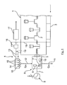
- In der einem Blockschaltbild entsprechenden
Fig. 1 ist mit dem Bezugszeichen 1 eine mehrzylindrische Hubkolben-Brennkraftmaschine bzw. ein Dieselmotor für ein Nutzkraftfahrzeug bezeichnet, die soweit nicht beschrieben herkömmlicher Bauart sein kann und deren Kurbelwelle 2 auf die übrigen Antriebseinrichtungen des Kraftfahrzeugs abtreibt. - Die Brennkraftmaschine 1 weist eine nur angedeutete Kraftstoff-Luft-Zuführeinrichtung mit einem Ansaugverteiler 3 und ein die Abgase abführendes Abgassystem 4 soweit nicht beschrieben bekannter Bauart auf. Gegebenenfalls könnte auch eine Abgasturboaufladung mit zumindest einer Abgasturbine im Abgassystem 4 vorgesehen sein.
- An die Brennkraftmaschine 1 bzw. an deren Kurbelwelle 2 ist zum Beispiel über eine schaltbare Kupplung und einen Drehzahlregler 5 ein Stirlingmotor 6 angekoppelt, dessen Antriebswelle 7 einerseits trieblich mit der Kurbelwelle 2 verbunden ist und andererseits auf eine elektrische Maschine 8, zum Beispiel einem Drehstromgenerator, abtreibt.
- Der Stirlingmotor 6 ist im Ausführungsbeispiel beispielhaft als Alpha-Typ ausgelegt, mit einem Arbeitskolben 9 und einem Verdrängerkolben 10, deren 90 Grad zueinander versetzte Zylinder (nicht dargestellt) in bekannter Weise in einem mehr oder minder geschlossenem Gaskreislauf miteinander korrespondieren, wobei in bekannter Weise der Zylinder des Verdrängerkolbens 10 als Wärmesenke (QAB) ausgeführt gekühlt ist (nur mit dem Pfeil 11 angedeutet), während der Zylinder des Arbeitskolben 9 durch Wärmezufuhr (QZU) beheizt ist. Der Stirlingmotor 6 könnte aber auch in bekannter Weise als Beta-Typ mit koaxialen Zylindern oder als Gamma-Typ ausgeführt sein.
- Die Kühlung QAB erfolgt entweder durch Fahrtwind zum Beispiel durch Anordnung von Kühlrippen an dem Zylinder des Verdrängerkolbens 10 und/oder durch Flüssigkeitskühlung mit Anschluss des Zylinders 10 bzw. eines entsprechenden Wärmeübertragers an das nicht dargestellte Kühlflüssigkeitssystem der Brennkraftmaschine 1.
- Zur Beheizung des Zylinders des Arbeitskolbens 9 des Stirlingmotors 6 (Pfeil 12) sind in das Abgassystem 4 bzw. in eine von den Brennräumen der Brennkraftmaschine 1 abgehende Abgasleitung 13 in einem Abgasgehäuse 14 mehrere Wärmerohre 15 eingesetzt, die die Abgasenthalpie bzw. Abwärme des Abgases zu dem Stirlingmotor 6 entweder direkt oder indirekt, zum Beispiel mittels eines Zwischenwärmeübertragers, transportieren.
- Stromab des Abgasgehäuses 14 mit den Wärmerohren 15 sind in dem Abgassystem 4 eine Ableitstelle bzw. ein Abgasrückführventil 16 einer nicht weiter dargestellten Abgasrückführeinrichtung der Brennkraftmaschine 1 und in Strömungsrichtung danach eine Abgasnachbehandlungseinrichtung mit einem SCR Katalysator 17 (selektive katalytische Reduktion) angeordnet.
- Über das Abgasrückführventil 16 und eine Abgasrückführleitung 18 kann Abgas in definierten Raten zum Ansaugverteiler 3 der Brennkraftmaschine 1 rückgeführt werden. Gegebenenfalls kann in der Abgasrückführleitung 18 ein an das Flüssigkeitskühlsystem der Brennkraftmaschine 1 angeschlossener Abgaskühler vorgesehen sein.
- Über den Stirlingmotor 6 kann bei Anordnung entsprechender Kupplungen (nicht dargestellt) an der Antriebswelle 7 entweder die durch die Wärmekopplung erzeugte Antriebsenergie auf die Kurbelwelle 2 und/oder auf die elektrische Maschine 8 zur Stromerzeugung in das Bordnetz des Kraftfahrzeugs geleitet werden. Die Maschine 8 kann gegebenenfalls auch als Elektromotor geschaltet als Startermotor dienen oder in einem Boostbetrieb zusätzliche Antriebsenergie liefern.
- In dem Abgassystem 4 bzw. in der Abgasleitung 13 können gegebenenfalls Mittel wie zum Beispiel eine steuerbare Bypassleitung 19 (gestrichelt angedeutet) vorgesehen sein, die eine Umgehung der Wärmerohre 15 bewirken. Damit kann zum Beispiel bei einem Kaltstart der Brennkraftmaschine 1 vorrangig eine Temperaturanhebung zum SCR Katalysator 17 erzielt werden.
-
- 1
- Brennkraftmaschine
- 2
- Kurbelwelle
- 3
- Ansaugverteiler
- 4
- Abgassystem
- 5
- Drehzahlregler
- 6
- Stirlingmotor
- 7
- Antriebswelle
- 8
- Elektromaschine
- 9
- Arbeitskolben
- 10
- Verdrängerkolben
- 11
- Wärmeabfuhr QAB (Wärmesenke des Stirlingmotors)
- 12
- Wärmezufuhr QZU (Wärmequelle des Stirlingmotors)
- 13
- Abgasleitung
- 14
- Abgasgehäuse
- 15
- Wärmerohre
- 16
- Abgasrückführventil
- 17
- SCR Katalysator
- 18
- Abgasrückführleitung
- 19
- Bypassleitung
Claims (15)
- Verfahren zum Betreiben einer Brennkraftmaschine, insbesondere für Nutzkraftfahrzeuge, mit einer Kraftstoff-Luft-Zuführeinrichtung und einem nachgeschalteten Abgassystem, dadurch gekennzeichnet, dass die Abgasenthalpie im Abgasstrom der Brennkraftmaschine (1) zum Betreiben einer Wärmekraftmaschine (6), insbesondere eines Stirlingmotors, genutzt wird, die mechanische Energie erzeugt.
- Verfahren nach Anspruch 1, dadurch gekennzeichnet, dass die Wärmekraftmaschine (6) zum Antrieb einer elektrischen Maschine (8) verwendet wird.
- Verfahren nach Anspruch 1 oder 2, dadurch gekennzeichnet, dass die Wärmekraftmaschine (6) mit ihrer Antriebswelle (7) mit der Kurbelwelle (2) der Brennkraftmaschine (1) gekoppelt wird, wobei bevorzugt vorgesehen ist, dass mittels eines Drehzahlreglers (5) die Drehzahl der Antriebswelle (7) der Wärmekraftmaschine (6) an die Momentandrehzahl der Kurbelwelle (2) der Brennkraftmaschine (1) angepasst wird.
- Verfahren nach einem der vorhergehenden Ansprüche, dadurch gekennzeichnet, dass die Abgasenthalpie im Abgasstrom der Brennkraftmaschine (1) als Antriebwärmestrom (QZU) zu der Wärmekraftmaschine (6) mittelbar, insbesondere unter Zwischenschaltung wenigstens eines Zwischenwärmeübertragers, oder unmittelbar übertragen wird.
- Verfahren nach Anspruch 4, dadurch gekennzeichnet, dass in eine Abgasleitung (13) des Abgassystems (4) der Brennkraftmaschine (1) wenigstens ein Wärmerohr (15), vorzugsweise mehrere Wärmerohre (15), eingesetzt ist, das die Wärmekraftmaschine (6), vorzugsweise einen dem Arbeitskolben (9) eines Stirlingmotors (6) zugeordneten Wärmeübertrager bzw. Wärmeübertragungsbereich, mittelbar, insbesondere unter Zwischenschaltung wenigstens eines Zwischenwärmeübertragers, oder unmittelbar mit einem Antriebwärmestrom (QZU) beaufschlagt.
- Verfahren nach Anspruch 5, dadurch gekennzeichnet, dass das wenigstens eine Wärmerohr (15) stromauf einer Abzweigstelle (16) für eine Abgasrückführeinrichtung der Brennkraftmaschine (1) angeordnet wird.
- Verfahren nach Anspruch 5 oder 6, dadurch gekennzeichnet, dass das wenigstens eine Wärmerohr (15) bei einer katalytischen Abgasnachbehandlungseinrichtung (17) stromauf der Nachbehandlungseinrichtung (17) vorgesehen wird.
- Verfahren nach Anspruch 7, dadurch gekennzeichnet, dass Mittel (19) zum Umgehen des wenigstens einen im Abgassystem (4) angeordneten Wärmerohres (15) verwendet werden.
- Vorrichtung, insbesondere zur Durchführung des Verfahrens nach einem der vorhergehenden Ansprüche, an einer Brennkraftmaschine (1) mit einer Kraftstoff-Luft-Zuführeinrichtung (3) und einem nachgeschaltetem Abgassystem (4), dadurch gekennzeichnet, dass das Abgassystem (4) über wenigstens ein Wärmerohr (15) wärmeübertragend an eine Wärmekraftmaschine (6), insbesondere an einen Stirlingmotor, angekoppelt ist, die elektrische und/oder mechanische Energie erzeugt.
- Vorrichtung nach Anspruch 9, dadurch gekennzeichnet, dass das wenigstens eine Wärmerohr (15) einen Antriebwärmestrom an die Wärmekraftmaschine (6), vorzugsweise an einen dem Arbeitskolben (9) des Stirlingmotors (6) zugeordneten Wärmeübertrager bzw. Wärmeübertragungsbereich, mittelbar, insbesondere unter Zwischenschaltung wenigstens eines Zwischenwärmeübertragers, oder unmittelbar überträgt.
- Vorrichtung nach Anspruch 9 oder 10, dadurch gekennzeichnet, dass die Wärmekraftmaschine (6) eine elektrische Maschine (8) antreibt und/oder dass die Wärmekraftmaschine(6) mit ihrer Antriebswelle (7) mit der Kurbelwelle (2) der Brennkraftmaschine (1) kuppelbar ist.
- Vorrichtung nach einem der Ansprüche 9 bis 11, dadurch gekennzeichnet, dass die Wärmesenke (QAB) der Wärmekraftmaschine (6) durch Fahrtwind des Kraftfahrzeugs gekühlt und/oder über einen Wärmeübertrager an ein Flüssigkeits-Kühlsystem der Brennkraftmaschine (1) angeschlossen ist.
- Vorrichtung nach einem der Ansprüche 9 bis 12, dadurch gekennzeichnet, dass bei einer Brennkraftmaschine (1) mit Abgasnachbehandlungseinrichtung (17) und/oder Abgasrückführeinrichtung (16) das wenigstens eine Wärmerohr (15) für die Wärmekraftmaschine (6) in ein Abgasgehäuse (14) des Abgassystems (4) integriert ist, das stromauf der Abgasnachbehandlungseinrichtung (17) und/oder der Abgasrückführableitung (16) positioniert ist.
- Brennkraftmaschine (1), insbesondere für Nutzkraftfahrzeuge, mit einer Vorrichtung nach einem der Ansprüche 9 bis 13.
- Fahrzeug, insbesondere Nutzfahrzeug, mit einer Vorrichtung nach einem der Ansprüche 9 bis 14.
Applications Claiming Priority (1)
| Application Number | Priority Date | Filing Date | Title |
|---|---|---|---|
| DE102013009219.1A DE102013009219A1 (de) | 2013-05-31 | 2013-05-31 | Verfahren und Vorrichtung zum Betreiben einer Brennkraftmaschine |
Publications (3)
| Publication Number | Publication Date |
|---|---|
| EP2808527A2 true EP2808527A2 (de) | 2014-12-03 |
| EP2808527A3 EP2808527A3 (de) | 2015-03-25 |
| EP2808527B1 EP2808527B1 (de) | 2021-03-10 |
Family
ID=49955184
Family Applications (1)
| Application Number | Title | Priority Date | Filing Date |
|---|---|---|---|
| EP14000133.0A Active EP2808527B1 (de) | 2013-05-31 | 2014-01-15 | Verfahren und vorrichtung zum betreiben einer brennkraftmaschine |
Country Status (3)
| Country | Link |
|---|---|
| US (1) | US9896986B2 (de) |
| EP (1) | EP2808527B1 (de) |
| DE (1) | DE102013009219A1 (de) |
Cited By (1)
| Publication number | Priority date | Publication date | Assignee | Title |
|---|---|---|---|---|
| CN105863835A (zh) * | 2016-05-03 | 2016-08-17 | 吴才华 | 发动机 |
Families Citing this family (5)
| Publication number | Priority date | Publication date | Assignee | Title |
|---|---|---|---|---|
| JP6624687B2 (ja) * | 2014-01-29 | 2019-12-25 | ヌオーヴォ ピニォーネ ソチエタ レスポンサビリタ リミタータNuovo Pignone S.R.L. | スターリングエンジンを有する圧縮機トレイン |
| AT516709B1 (de) * | 2015-06-15 | 2016-08-15 | Avl List Gmbh | Brennkraftmaschine mit einem abwärmerückgewinnungssystem |
| DE102018005821B3 (de) | 2018-07-25 | 2019-05-09 | Adrian Verstallen | Vorrichtung zur in-situ Herstellung eines Wasser-in-Diesel-Kraftstoffes mit Nutzung der Abgas-Enthalpie und des Wassers im Abgas, um den Wirkungsgrad eines Dieselmotors in einem Nutzfahrzeug zu erhöhen und die Schadstoffemissionen zu minimieren |
| KR102598538B1 (ko) * | 2018-10-22 | 2023-11-03 | 현대자동차주식회사 | 차량용 배기 테일 트림 |
| PL443093A1 (pl) * | 2022-12-09 | 2024-05-20 | Stanisław Szarek | Silnik hybrydowy |
Family Cites Families (26)
| Publication number | Priority date | Publication date | Assignee | Title |
|---|---|---|---|---|
| US4235077A (en) * | 1978-10-30 | 1980-11-25 | Bryant Clyde C | Combination engine |
| US4392351A (en) * | 1980-02-25 | 1983-07-12 | Doundoulakis George J | Multi-cylinder stirling engine |
| US4481771A (en) * | 1982-08-06 | 1984-11-13 | Stirling Thermal Motors, Inc. | Heat exchanger stack apparatus |
| DE19955313C2 (de) * | 1999-11-17 | 2003-12-18 | Jungheinrich Ag | Antriebssystem für Flurförderzeuge |
| US6543229B2 (en) * | 2000-06-14 | 2003-04-08 | Stm Power, Inc. | Exhaust gas alternator system |
| DE60213635T8 (de) * | 2001-10-19 | 2007-12-13 | Honda Giken Kogyo K.K. | Vorrichtung zur überwachung des zustands eines kohlenwasserstoffadsorptionsmittels |
| US7100369B2 (en) * | 2003-05-06 | 2006-09-05 | Denso Corporation | Thermoelectric generating device |
| JP2005306280A (ja) * | 2004-04-23 | 2005-11-04 | Toyota Motor Corp | 車両 |
| US7076941B1 (en) * | 2005-08-05 | 2006-07-18 | Renewable Thermodynamics Llc | Externally heated engine |
| JP4706536B2 (ja) * | 2006-03-30 | 2011-06-22 | トヨタ自動車株式会社 | 排熱回収装置 |
| GB2437309B (en) * | 2006-04-22 | 2011-09-14 | Ford Global Tech Llc | A cooling system for an engine |
| US7490469B2 (en) * | 2006-08-07 | 2009-02-17 | United Technologies Corporation | Dual-function stirling engine system |
| US7984684B2 (en) * | 2006-10-06 | 2011-07-26 | Mitja Victor Hinderks | Marine hulls and drives |
| JP2008255900A (ja) * | 2007-04-05 | 2008-10-23 | Toyota Motor Corp | 動力伝達機構及び排熱回収装置 |
| DE102007054197A1 (de) * | 2007-11-14 | 2009-05-20 | Bayerische Motoren Werke Aktiengesellschaft | Antriebssystem für ein Fahrzeug |
| DE202008000832U1 (de) * | 2008-01-21 | 2008-03-20 | Vitek, Christian, Dipl.-Ing. (FH) | Thermoelektrischer Generator |
| JP4737230B2 (ja) * | 2008-05-23 | 2011-07-27 | トヨタ自動車株式会社 | 排熱回収システム |
| US20100024859A1 (en) * | 2008-07-29 | 2010-02-04 | Bsst, Llc. | Thermoelectric power generator for variable thermal power source |
| JP4609577B2 (ja) * | 2008-12-17 | 2011-01-12 | トヨタ自動車株式会社 | ピストン機関 |
| US8162797B2 (en) * | 2009-02-04 | 2012-04-24 | Ford Global Technologies, Llc | Methods and systems for heating transmission fluid |
| US20100274396A1 (en) * | 2009-04-24 | 2010-10-28 | Gm Global Technology Operations, Inc. | Thermoelectric climate control |
| GB2474021B (en) * | 2009-09-30 | 2016-03-30 | Stephen Francis Mongan | Electricity-generating installation |
| US8726661B2 (en) * | 2010-08-09 | 2014-05-20 | GM Global Technology Operations LLC | Hybrid powertrain system including an internal combustion engine and a stirling engine |
| JP2012233461A (ja) * | 2011-05-09 | 2012-11-29 | Toyota Industries Corp | ランキンサイクル装置 |
| US9476340B2 (en) * | 2012-04-16 | 2016-10-25 | GM Global Technology Operations LLC | Vehicle with stirling engine integrated into engine exhaust system |
| JP2014185793A (ja) * | 2013-03-22 | 2014-10-02 | Hitachi Metals Ltd | ヒートパイプ及びヒートパイプ用複合材 |
-
2013
- 2013-05-31 DE DE102013009219.1A patent/DE102013009219A1/de not_active Withdrawn
-
2014
- 2014-01-15 EP EP14000133.0A patent/EP2808527B1/de active Active
- 2014-05-15 US US14/277,994 patent/US9896986B2/en active Active
Non-Patent Citations (1)
| Title |
|---|
| None |
Cited By (1)
| Publication number | Priority date | Publication date | Assignee | Title |
|---|---|---|---|---|
| CN105863835A (zh) * | 2016-05-03 | 2016-08-17 | 吴才华 | 发动机 |
Also Published As
| Publication number | Publication date |
|---|---|
| US20140352296A1 (en) | 2014-12-04 |
| DE102013009219A1 (de) | 2014-12-04 |
| EP2808527B1 (de) | 2021-03-10 |
| EP2808527A3 (de) | 2015-03-25 |
| US9896986B2 (en) | 2018-02-20 |
Similar Documents
| Publication | Publication Date | Title |
|---|---|---|
| DE102008061026B4 (de) | Fahrzeug und Verfahren zum selektiven Absorbieren von Abwärme von Abgasen | |
| EP2808527B1 (de) | Verfahren und vorrichtung zum betreiben einer brennkraftmaschine | |
| EP2064415B1 (de) | Wärmetauscheranordnung | |
| EP2375025B1 (de) | Kühlkreislauf für eine Brennkraftmaschine | |
| DE102006057247A1 (de) | Aufladeeinrichtung | |
| WO2010000284A2 (de) | Abgasenergienutzung mittels geschlossenem dampfkraftprozess | |
| EP3751107B1 (de) | Verbrennungsmotor mit abgaswärmerückgewinnungssystem sowie verfahren zur abgaswärmerückgewinnung | |
| DE102018127241A1 (de) | Durch abwärme angetriebene abgaspumpe | |
| DE102015215518A1 (de) | System zur Energierückgewinnung aus dem Abgas einer Brennkraftmaschine | |
| EP3739180B1 (de) | Kühlkreislaufanordnung einer verbrennungskraftmaschine | |
| DE102010048918B4 (de) | Abgassystem und Verfahren zum Abführen von Abgas einer Brennkraftmaschine | |
| DE102008051843A1 (de) | Brennkraftmaschine | |
| CH709404A1 (de) | Antriebssystem mit einem Verbrennungsmotor und einem Energierückgewinnungssystem. | |
| EP3023622B1 (de) | Kühlsystem für ein fahrzeug, insbesondere für ein nutzfahrzeug | |
| EP3693591A1 (de) | Abwärmenutzung | |
| DE102008031122B4 (de) | Anordnung zum Aufheizen eines Kraftfahrzeuggetriebes | |
| AT505717A2 (de) | Verfahren zum betreiben eines antriebssystems | |
| DE102012001675A1 (de) | Kreislaufanordnung zur Kühlung von Verbrennungsluft einer Verbrennungskraftmaschine eines Kraftfahrzeugs und Verfahren zum Betrieb einer Kreislaufanordnung zur Kühlung von Verbrennungsluft einer Verbrennungskraftmaschine eines Kraftfahrzeugs | |
| DE102018101999A1 (de) | Kühlkreislaufanordnung einer Verbrennungskraftmaschine und Verfahren zum Betrieb eines Kraftfahrzeuges | |
| EP3951140B1 (de) | Vorrichtung zur energierückgewinnung mit einem abwärmenutzungskreislauf | |
| WO1997047865A1 (de) | Kraftfahrzeug mit einer brennkraftmaschine mit äusserer abgasrückführung und heizvorrichtung | |
| EP2733339B1 (de) | Vorrichtung zur Nutzung der Abwärme einer Brennkraftmaschine | |
| EP2930321B1 (de) | Antriebsvorrichtung eines Kraftfahrzeugs mit einem Gasturbinensystem zur Energierückgewinnung und Verfahren zum Betrieb der Antriebsvorrichtung | |
| DE102015206458A1 (de) | Anordnung mit Organic-Rankine-Cycle zur Ladeluftverdichtung | |
| DE102017011849A1 (de) | Anordnung zur Umwandlung thermischer Energie aus Verlustwärme einer Verbrennungskraftmaschine |
Legal Events
| Date | Code | Title | Description |
|---|---|---|---|
| PUAI | Public reference made under article 153(3) epc to a published international application that has entered the european phase |
Free format text: ORIGINAL CODE: 0009012 |
|
| 17P | Request for examination filed |
Effective date: 20140115 |
|
| AK | Designated contracting states |
Kind code of ref document: A2 Designated state(s): AL AT BE BG CH CY CZ DE DK EE ES FI FR GB GR HR HU IE IS IT LI LT LU LV MC MK MT NL NO PL PT RO RS SE SI SK SM TR |
|
| AX | Request for extension of the european patent |
Extension state: BA ME |
|
| PUAL | Search report despatched |
Free format text: ORIGINAL CODE: 0009013 |
|
| AK | Designated contracting states |
Kind code of ref document: A3 Designated state(s): AL AT BE BG CH CY CZ DE DK EE ES FI FR GB GR HR HU IE IS IT LI LT LU LV MC MK MT NL NO PL PT RO RS SE SI SK SM TR |
|
| AX | Request for extension of the european patent |
Extension state: BA ME |
|
| RIC1 | Information provided on ipc code assigned before grant |
Ipc: F02G 1/043 20060101AFI20150216BHEP Ipc: F01K 23/06 20060101ALI20150216BHEP Ipc: F02G 5/02 20060101ALI20150216BHEP Ipc: F28D 15/00 20060101ALI20150216BHEP |
|
| R17P | Request for examination filed (corrected) |
Effective date: 20150225 |
|
| STAA | Information on the status of an ep patent application or granted ep patent |
Free format text: STATUS: EXAMINATION IS IN PROGRESS |
|
| 17Q | First examination report despatched |
Effective date: 20161220 |
|
| RAP1 | Party data changed (applicant data changed or rights of an application transferred) |
Owner name: MAN TRUCK & BUS SE |
|
| GRAP | Despatch of communication of intention to grant a patent |
Free format text: ORIGINAL CODE: EPIDOSNIGR1 |
|
| STAA | Information on the status of an ep patent application or granted ep patent |
Free format text: STATUS: GRANT OF PATENT IS INTENDED |
|
| INTG | Intention to grant announced |
Effective date: 20200907 |
|
| GRAS | Grant fee paid |
Free format text: ORIGINAL CODE: EPIDOSNIGR3 |
|
| GRAA | (expected) grant |
Free format text: ORIGINAL CODE: 0009210 |
|
| STAA | Information on the status of an ep patent application or granted ep patent |
Free format text: STATUS: THE PATENT HAS BEEN GRANTED |
|
| AK | Designated contracting states |
Kind code of ref document: B1 Designated state(s): AL AT BE BG CH CY CZ DE DK EE ES FI FR GB GR HR HU IE IS IT LI LT LU LV MC MK MT NL NO PL PT RO RS SE SI SK SM TR |
|
| REG | Reference to a national code |
Ref country code: GB Ref legal event code: FG4D Free format text: NOT ENGLISH |
|
| REG | Reference to a national code |
Ref country code: CH Ref legal event code: EP Ref country code: AT Ref legal event code: REF Ref document number: 1370054 Country of ref document: AT Kind code of ref document: T Effective date: 20210315 |
|
| REG | Reference to a national code |
Ref country code: DE Ref legal event code: R096 Ref document number: 502014015347 Country of ref document: DE |
|
| REG | Reference to a national code |
Ref country code: IE Ref legal event code: FG4D Free format text: LANGUAGE OF EP DOCUMENT: GERMAN |
|
| REG | Reference to a national code |
Ref country code: NL Ref legal event code: FP |
|
| REG | Reference to a national code |
Ref country code: SE Ref legal event code: TRGR |
|
| REG | Reference to a national code |
Ref country code: LT Ref legal event code: MG9D |
|
| PG25 | Lapsed in a contracting state [announced via postgrant information from national office to epo] |
Ref country code: NO Free format text: LAPSE BECAUSE OF FAILURE TO SUBMIT A TRANSLATION OF THE DESCRIPTION OR TO PAY THE FEE WITHIN THE PRESCRIBED TIME-LIMIT Effective date: 20210610 Ref country code: BG Free format text: LAPSE BECAUSE OF FAILURE TO SUBMIT A TRANSLATION OF THE DESCRIPTION OR TO PAY THE FEE WITHIN THE PRESCRIBED TIME-LIMIT Effective date: 20210610 Ref country code: LT Free format text: LAPSE BECAUSE OF FAILURE TO SUBMIT A TRANSLATION OF THE DESCRIPTION OR TO PAY THE FEE WITHIN THE PRESCRIBED TIME-LIMIT Effective date: 20210310 Ref country code: FI Free format text: LAPSE BECAUSE OF FAILURE TO SUBMIT A TRANSLATION OF THE DESCRIPTION OR TO PAY THE FEE WITHIN THE PRESCRIBED TIME-LIMIT Effective date: 20210310 Ref country code: HR Free format text: LAPSE BECAUSE OF FAILURE TO SUBMIT A TRANSLATION OF THE DESCRIPTION OR TO PAY THE FEE WITHIN THE PRESCRIBED TIME-LIMIT Effective date: 20210310 Ref country code: GR Free format text: LAPSE BECAUSE OF FAILURE TO SUBMIT A TRANSLATION OF THE DESCRIPTION OR TO PAY THE FEE WITHIN THE PRESCRIBED TIME-LIMIT Effective date: 20210611 |
|
| PG25 | Lapsed in a contracting state [announced via postgrant information from national office to epo] |
Ref country code: LV Free format text: LAPSE BECAUSE OF FAILURE TO SUBMIT A TRANSLATION OF THE DESCRIPTION OR TO PAY THE FEE WITHIN THE PRESCRIBED TIME-LIMIT Effective date: 20210310 Ref country code: RS Free format text: LAPSE BECAUSE OF FAILURE TO SUBMIT A TRANSLATION OF THE DESCRIPTION OR TO PAY THE FEE WITHIN THE PRESCRIBED TIME-LIMIT Effective date: 20210310 |
|
| PG25 | Lapsed in a contracting state [announced via postgrant information from national office to epo] |
Ref country code: SM Free format text: LAPSE BECAUSE OF FAILURE TO SUBMIT A TRANSLATION OF THE DESCRIPTION OR TO PAY THE FEE WITHIN THE PRESCRIBED TIME-LIMIT Effective date: 20210310 Ref country code: CZ Free format text: LAPSE BECAUSE OF FAILURE TO SUBMIT A TRANSLATION OF THE DESCRIPTION OR TO PAY THE FEE WITHIN THE PRESCRIBED TIME-LIMIT Effective date: 20210310 Ref country code: EE Free format text: LAPSE BECAUSE OF FAILURE TO SUBMIT A TRANSLATION OF THE DESCRIPTION OR TO PAY THE FEE WITHIN THE PRESCRIBED TIME-LIMIT Effective date: 20210310 |
|
| PG25 | Lapsed in a contracting state [announced via postgrant information from national office to epo] |
Ref country code: IS Free format text: LAPSE BECAUSE OF FAILURE TO SUBMIT A TRANSLATION OF THE DESCRIPTION OR TO PAY THE FEE WITHIN THE PRESCRIBED TIME-LIMIT Effective date: 20210710 Ref country code: SK Free format text: LAPSE BECAUSE OF FAILURE TO SUBMIT A TRANSLATION OF THE DESCRIPTION OR TO PAY THE FEE WITHIN THE PRESCRIBED TIME-LIMIT Effective date: 20210310 Ref country code: RO Free format text: LAPSE BECAUSE OF FAILURE TO SUBMIT A TRANSLATION OF THE DESCRIPTION OR TO PAY THE FEE WITHIN THE PRESCRIBED TIME-LIMIT Effective date: 20210310 Ref country code: PT Free format text: LAPSE BECAUSE OF FAILURE TO SUBMIT A TRANSLATION OF THE DESCRIPTION OR TO PAY THE FEE WITHIN THE PRESCRIBED TIME-LIMIT Effective date: 20210712 Ref country code: PL Free format text: LAPSE BECAUSE OF FAILURE TO SUBMIT A TRANSLATION OF THE DESCRIPTION OR TO PAY THE FEE WITHIN THE PRESCRIBED TIME-LIMIT Effective date: 20210310 Ref country code: ES Free format text: LAPSE BECAUSE OF FAILURE TO SUBMIT A TRANSLATION OF THE DESCRIPTION OR TO PAY THE FEE WITHIN THE PRESCRIBED TIME-LIMIT Effective date: 20210310 |
|
| REG | Reference to a national code |
Ref country code: DE Ref legal event code: R097 Ref document number: 502014015347 Country of ref document: DE |
|
| PLBE | No opposition filed within time limit |
Free format text: ORIGINAL CODE: 0009261 |
|
| STAA | Information on the status of an ep patent application or granted ep patent |
Free format text: STATUS: NO OPPOSITION FILED WITHIN TIME LIMIT |
|
| PG25 | Lapsed in a contracting state [announced via postgrant information from national office to epo] |
Ref country code: AL Free format text: LAPSE BECAUSE OF FAILURE TO SUBMIT A TRANSLATION OF THE DESCRIPTION OR TO PAY THE FEE WITHIN THE PRESCRIBED TIME-LIMIT Effective date: 20210310 Ref country code: DK Free format text: LAPSE BECAUSE OF FAILURE TO SUBMIT A TRANSLATION OF THE DESCRIPTION OR TO PAY THE FEE WITHIN THE PRESCRIBED TIME-LIMIT Effective date: 20210310 |
|
| 26N | No opposition filed |
Effective date: 20211213 |
|
| PG25 | Lapsed in a contracting state [announced via postgrant information from national office to epo] |
Ref country code: SI Free format text: LAPSE BECAUSE OF FAILURE TO SUBMIT A TRANSLATION OF THE DESCRIPTION OR TO PAY THE FEE WITHIN THE PRESCRIBED TIME-LIMIT Effective date: 20210310 |
|
| PG25 | Lapsed in a contracting state [announced via postgrant information from national office to epo] |
Ref country code: IS Free format text: LAPSE BECAUSE OF FAILURE TO SUBMIT A TRANSLATION OF THE DESCRIPTION OR TO PAY THE FEE WITHIN THE PRESCRIBED TIME-LIMIT Effective date: 20210710 |
|
| PG25 | Lapsed in a contracting state [announced via postgrant information from national office to epo] |
Ref country code: MC Free format text: LAPSE BECAUSE OF FAILURE TO SUBMIT A TRANSLATION OF THE DESCRIPTION OR TO PAY THE FEE WITHIN THE PRESCRIBED TIME-LIMIT Effective date: 20210310 |
|
| REG | Reference to a national code |
Ref country code: CH Ref legal event code: PL |
|
| GBPC | Gb: european patent ceased through non-payment of renewal fee |
Effective date: 20220115 |
|
| REG | Reference to a national code |
Ref country code: BE Ref legal event code: MM Effective date: 20220131 |
|
| PG25 | Lapsed in a contracting state [announced via postgrant information from national office to epo] |
Ref country code: LU Free format text: LAPSE BECAUSE OF NON-PAYMENT OF DUE FEES Effective date: 20220115 Ref country code: GB Free format text: LAPSE BECAUSE OF NON-PAYMENT OF DUE FEES Effective date: 20220115 |
|
| PG25 | Lapsed in a contracting state [announced via postgrant information from national office to epo] |
Ref country code: BE Free format text: LAPSE BECAUSE OF NON-PAYMENT OF DUE FEES Effective date: 20220131 |
|
| PG25 | Lapsed in a contracting state [announced via postgrant information from national office to epo] |
Ref country code: LI Free format text: LAPSE BECAUSE OF NON-PAYMENT OF DUE FEES Effective date: 20220131 Ref country code: CH Free format text: LAPSE BECAUSE OF NON-PAYMENT OF DUE FEES Effective date: 20220131 |
|
| PG25 | Lapsed in a contracting state [announced via postgrant information from national office to epo] |
Ref country code: IE Free format text: LAPSE BECAUSE OF NON-PAYMENT OF DUE FEES Effective date: 20220115 |
|
| REG | Reference to a national code |
Ref country code: AT Ref legal event code: MM01 Ref document number: 1370054 Country of ref document: AT Kind code of ref document: T Effective date: 20220115 |
|
| PG25 | Lapsed in a contracting state [announced via postgrant information from national office to epo] |
Ref country code: AT Free format text: LAPSE BECAUSE OF NON-PAYMENT OF DUE FEES Effective date: 20220115 |
|
| PG25 | Lapsed in a contracting state [announced via postgrant information from national office to epo] |
Ref country code: HU Free format text: LAPSE BECAUSE OF FAILURE TO SUBMIT A TRANSLATION OF THE DESCRIPTION OR TO PAY THE FEE WITHIN THE PRESCRIBED TIME-LIMIT; INVALID AB INITIO Effective date: 20140115 |
|
| PG25 | Lapsed in a contracting state [announced via postgrant information from national office to epo] |
Ref country code: MK Free format text: LAPSE BECAUSE OF FAILURE TO SUBMIT A TRANSLATION OF THE DESCRIPTION OR TO PAY THE FEE WITHIN THE PRESCRIBED TIME-LIMIT Effective date: 20210310 Ref country code: CY Free format text: LAPSE BECAUSE OF FAILURE TO SUBMIT A TRANSLATION OF THE DESCRIPTION OR TO PAY THE FEE WITHIN THE PRESCRIBED TIME-LIMIT Effective date: 20210310 |
|
| PG25 | Lapsed in a contracting state [announced via postgrant information from national office to epo] |
Ref country code: MT Free format text: LAPSE BECAUSE OF FAILURE TO SUBMIT A TRANSLATION OF THE DESCRIPTION OR TO PAY THE FEE WITHIN THE PRESCRIBED TIME-LIMIT Effective date: 20210310 |
|
| PG25 | Lapsed in a contracting state [announced via postgrant information from national office to epo] |
Ref country code: TR Free format text: LAPSE BECAUSE OF FAILURE TO SUBMIT A TRANSLATION OF THE DESCRIPTION OR TO PAY THE FEE WITHIN THE PRESCRIBED TIME-LIMIT Effective date: 20210310 |
|
| PGFP | Annual fee paid to national office [announced via postgrant information from national office to epo] |
Ref country code: NL Payment date: 20260122 Year of fee payment: 13 |
|
| PGFP | Annual fee paid to national office [announced via postgrant information from national office to epo] |
Ref country code: SE Payment date: 20260126 Year of fee payment: 13 |
|
| PGFP | Annual fee paid to national office [announced via postgrant information from national office to epo] |
Ref country code: DE Payment date: 20260127 Year of fee payment: 13 |
|
| PGFP | Annual fee paid to national office [announced via postgrant information from national office to epo] |
Ref country code: IT Payment date: 20260123 Year of fee payment: 13 |
|
| PGFP | Annual fee paid to national office [announced via postgrant information from national office to epo] |
Ref country code: FR Payment date: 20260127 Year of fee payment: 13 |