EP2808530A1 - Appareil et procédé de traitement d'un fluide quelconque ou d'un mélange de fluides ou de tout gaz ou mélange de gaz tel que l'air, et en particulier, un mélange d'hydrocarbures liquides ou gazeux avec de l'air - Google Patents
Appareil et procédé de traitement d'un fluide quelconque ou d'un mélange de fluides ou de tout gaz ou mélange de gaz tel que l'air, et en particulier, un mélange d'hydrocarbures liquides ou gazeux avec de l'air Download PDFInfo
- Publication number
- EP2808530A1 EP2808530A1 EP14001579.3A EP14001579A EP2808530A1 EP 2808530 A1 EP2808530 A1 EP 2808530A1 EP 14001579 A EP14001579 A EP 14001579A EP 2808530 A1 EP2808530 A1 EP 2808530A1
- Authority
- EP
- European Patent Office
- Prior art keywords
- magnetic
- connection
- inner tube
- rings
- central
- Prior art date
- Legal status (The legal status is an assumption and is not a legal conclusion. Google has not performed a legal analysis and makes no representation as to the accuracy of the status listed.)
- Withdrawn
Links
- 239000000203 mixture Substances 0.000 title claims abstract description 36
- 239000012530 fluid Substances 0.000 title claims abstract description 34
- 229930195733 hydrocarbon Natural products 0.000 title claims abstract description 23
- 150000002430 hydrocarbons Chemical class 0.000 title claims abstract description 23
- 239000007789 gas Substances 0.000 title claims description 14
- 238000000034 method Methods 0.000 title claims description 8
- 230000005291 magnetic effect Effects 0.000 claims abstract description 178
- 238000002485 combustion reaction Methods 0.000 claims abstract description 27
- 239000004215 Carbon black (E152) Substances 0.000 claims abstract description 20
- 125000006850 spacer group Chemical group 0.000 claims description 22
- 239000000470 constituent Substances 0.000 claims description 7
- 230000008859 change Effects 0.000 claims description 6
- 230000008569 process Effects 0.000 claims description 4
- XLYOFNOQVPJJNP-UHFFFAOYSA-N water Substances O XLYOFNOQVPJJNP-UHFFFAOYSA-N 0.000 claims description 4
- 239000007788 liquid Substances 0.000 claims description 3
- 239000008267 milk Substances 0.000 claims description 2
- 210000004080 milk Anatomy 0.000 claims description 2
- 235000013336 milk Nutrition 0.000 claims description 2
- 239000000463 material Substances 0.000 description 9
- RYGMFSIKBFXOCR-UHFFFAOYSA-N Copper Chemical compound [Cu] RYGMFSIKBFXOCR-UHFFFAOYSA-N 0.000 description 6
- 239000010949 copper Substances 0.000 description 6
- 229910052802 copper Inorganic materials 0.000 description 6
- 125000004429 atom Chemical group 0.000 description 5
- 230000003993 interaction Effects 0.000 description 3
- 230000009467 reduction Effects 0.000 description 3
- 229910001369 Brass Inorganic materials 0.000 description 2
- QVGXLLKOCUKJST-UHFFFAOYSA-N atomic oxygen Chemical compound [O] QVGXLLKOCUKJST-UHFFFAOYSA-N 0.000 description 2
- 239000010951 brass Substances 0.000 description 2
- 230000008878 coupling Effects 0.000 description 2
- 238000010168 coupling process Methods 0.000 description 2
- 238000005859 coupling reaction Methods 0.000 description 2
- 125000004435 hydrogen atom Chemical group [H]* 0.000 description 2
- 239000001301 oxygen Substances 0.000 description 2
- 229910052760 oxygen Inorganic materials 0.000 description 2
- OKTJSMMVPCPJKN-UHFFFAOYSA-N Carbon Chemical compound [C] OKTJSMMVPCPJKN-UHFFFAOYSA-N 0.000 description 1
- 229910052772 Samarium Inorganic materials 0.000 description 1
- 230000004913 activation Effects 0.000 description 1
- 229910052799 carbon Inorganic materials 0.000 description 1
- 125000004432 carbon atom Chemical group C* 0.000 description 1
- 238000006243 chemical reaction Methods 0.000 description 1
- 230000001427 coherent effect Effects 0.000 description 1
- 150000001875 compounds Chemical class 0.000 description 1
- 239000004020 conductor Substances 0.000 description 1
- 230000000694 effects Effects 0.000 description 1
- 238000009429 electrical wiring Methods 0.000 description 1
- 230000005611 electricity Effects 0.000 description 1
- 230000003631 expected effect Effects 0.000 description 1
- 235000013305 food Nutrition 0.000 description 1
- 230000005415 magnetization Effects 0.000 description 1
- 230000004048 modification Effects 0.000 description 1
- 238000012986 modification Methods 0.000 description 1
- 230000005298 paramagnetic effect Effects 0.000 description 1
- 230000002093 peripheral effect Effects 0.000 description 1
- 230000010287 polarization Effects 0.000 description 1
- 230000001681 protective effect Effects 0.000 description 1
- KZUNJOHGWZRPMI-UHFFFAOYSA-N samarium atom Chemical compound [Sm] KZUNJOHGWZRPMI-UHFFFAOYSA-N 0.000 description 1
- 229910001220 stainless steel Inorganic materials 0.000 description 1
- 239000010935 stainless steel Substances 0.000 description 1
- 238000005728 strengthening Methods 0.000 description 1
- 239000000126 substance Substances 0.000 description 1
- 229910000859 α-Fe Inorganic materials 0.000 description 1
Images







Classifications
-
- B—PERFORMING OPERATIONS; TRANSPORTING
- B01—PHYSICAL OR CHEMICAL PROCESSES OR APPARATUS IN GENERAL
- B01J—CHEMICAL OR PHYSICAL PROCESSES, e.g. CATALYSIS OR COLLOID CHEMISTRY; THEIR RELEVANT APPARATUS
- B01J19/00—Chemical, physical or physico-chemical processes in general; Their relevant apparatus
- B01J19/08—Processes employing the direct application of electric or wave energy, or particle radiation; Apparatus therefor
- B01J19/087—Processes employing the direct application of electric or wave energy, or particle radiation; Apparatus therefor employing electric or magnetic energy
-
- F—MECHANICAL ENGINEERING; LIGHTING; HEATING; WEAPONS; BLASTING
- F23—COMBUSTION APPARATUS; COMBUSTION PROCESSES
- F23C—METHODS OR APPARATUS FOR COMBUSTION USING FLUID FUEL OR SOLID FUEL SUSPENDED IN A CARRIER GAS OR AIR
- F23C99/00—Subject-matter not provided for in other groups of this subclass
- F23C99/001—Applying electric means or magnetism to combustion
-
- B—PERFORMING OPERATIONS; TRANSPORTING
- B01—PHYSICAL OR CHEMICAL PROCESSES OR APPARATUS IN GENERAL
- B01J—CHEMICAL OR PHYSICAL PROCESSES, e.g. CATALYSIS OR COLLOID CHEMISTRY; THEIR RELEVANT APPARATUS
- B01J2219/00—Chemical, physical or physico-chemical processes in general; Their relevant apparatus
- B01J2219/08—Processes employing the direct application of electric or wave energy, or particle radiation; Apparatus therefor
- B01J2219/0803—Processes employing the direct application of electric or wave energy, or particle radiation; Apparatus therefor employing electric or magnetic energy
- B01J2219/085—Processes employing the direct application of electric or wave energy, or particle radiation; Apparatus therefor employing electric or magnetic energy creating magnetic fields
-
- F—MECHANICAL ENGINEERING; LIGHTING; HEATING; WEAPONS; BLASTING
- F02—COMBUSTION ENGINES; HOT-GAS OR COMBUSTION-PRODUCT ENGINE PLANTS
- F02M—SUPPLYING COMBUSTION ENGINES IN GENERAL WITH COMBUSTIBLE MIXTURES OR CONSTITUENTS THEREOF
- F02M27/00—Apparatus for treating combustion-air, fuel, or fuel-air mixture, by catalysts, electric means, magnetism, rays, sound waves, or the like
- F02M27/04—Apparatus for treating combustion-air, fuel, or fuel-air mixture, by catalysts, electric means, magnetism, rays, sound waves, or the like by electric means, ionisation, polarisation or magnetism
- F02M27/045—Apparatus for treating combustion-air, fuel, or fuel-air mixture, by catalysts, electric means, magnetism, rays, sound waves, or the like by electric means, ionisation, polarisation or magnetism by permanent magnets
-
- F—MECHANICAL ENGINEERING; LIGHTING; HEATING; WEAPONS; BLASTING
- F23—COMBUSTION APPARATUS; COMBUSTION PROCESSES
- F23K—FEEDING FUEL TO COMBUSTION APPARATUS
- F23K2900/00—Special features of, or arrangements for fuel supplies
- F23K2900/01002—Treating solid fuel with electromagnetic fields before combustion
Definitions
- the present disclosure relates to the field of ecological systems exploiting the natural effects of magnetic fields on fluids, and particularly a device for improving the combustion of mixtures comprising fluids or gaseous hydrocarbons with air.
- the system does not require any electrical wiring since it only uses the natural magnetic field.
- the hydrocarbons can be defined as a set of chemical compounds, consisting essentially of carbon atoms and hydrogen atoms which are bonded together by means of the co-participation of valence electrons having a binding/association energy.
- a fluid Under dynamic conditions, when being subject to a magnetic field, a fluid can absorb forces exerted both at the electronic and the nucleic level. Changing the orbits of most peripheral electrons also gives rise to the modification of the electronic properties of a single atom or molecule and therefore the ability to chemically interact with another atom or molecule.
- Combustible molecules comprise hydrogen atoms which are all placed outwardly, whereas the atoms of carbon occupy the inner portion of the molecule.
- the properties of the chemical bond - and the sequence of chemical reactions which are likely to occur - determine to which type one atom belongs and is ruled by the laws governing the atomic cloud.
- Another object of the present disclosure is to provide an apparatus adapted to improve the combustion of a fluid or gaseous hydrocarbon mixture with combustion air.
- a further object is to provide an apparatus adapted to process any fluid or mixture of fluids or any gas or mixture of gases requiring a specific physical magnetic change in the structure of some of its constituents.
- an apparatus for improving the combustion of a mixture of fluid or gaseous hydrocarbon with combustion air comprising:
- the apparatus further comprises a closed housing for protecting the magnetic rings as well as the connecting bridges.
- the closed housing comprises an outer tube fitted with two lateral flanges, having apertures on both sides for the inner tube.
- the apparatus comprises spacers for holding a respective distance between the magnetic rings and for preventing inadvertent connection between the connecting bridges and the wall of the housing.
- the spacers have the shape of sleeves for maintaining a predetermined distance between the central magnetic ring and each of the magnetic rings located at both ends of the inner tube.
- the apparatus further comprises spacers having the shape of sleeves for the purpose of maintaining a predetermined spacing between said magnetic rings located at both ends of the tube and the corresponding lateral flange of the housing.
- the disclosure further achieves a process for improving the combustion of a mixture of fluid or gaseous hydrocarbon with combustion air, comprising the following method steps:
- the disclosure further provides an apparatus for treating a fluid or mixture of fluids requiring a specific physical magnetic change in the structure of some of its constituents, comprising:
- the disclosure further provides an apparatus for improving the combustion of any gas or mixture of gases, such as air, comprising:
- the apparatus comprises a first inner tube 10 for enabling the flow of fluid or gaseous hydrocarbon mixture.
- the device further comprises two fittings, or couplers/connectors 1 and 2 being located at both sides of inner tube 10., flanged or threaded in accordance with the particular application being considered, and the particular flow of combustible material being desired.
- the practical dimensioning of fittings 1 and 2, as well as that of tube 10, will depend on the flow of fluid to be processed within the device.
- the tube 10 and fittings or couplers/connectors 1 and 2 are formed of stainless steel, for example AISI Type 304 or their food version for the conduction of water AISI 316 L.
- the apparatus further comprises a set of three magnets or magnetic rings 11-12-13 which are located along the inner tube 10 for the purpose of generating an axial magnetic field. More specifically, there is provided a central ring 11 (e.g. of 20mm width for fitting a % inch coupling) as well as, located on either side of the tube 10, two magnetic rings 12 and 13 of a smaller size ( by example of width 15mm fitting 3 ⁇ 4 inch ).
- a central ring 11 e.g. of 20mm width for fitting a % inch coupling
- two magnetic rings 12 and 13 of a smaller size (by example of width 15mm fitting 3 ⁇ 4 inch ).
- the magnetic rings 11-13 are formed of a ferrite and Samarium type material so as to generate a significant axial magnetic field within the hydrocarbon molecules and the air flowing within the inner tube 10. More specifically, the magnetic field may have a magnitude of 1000 to 3000 Gauss, and preferably 2000 Gauss.
- the magnetic rings 11-13 are held in place on the inner tube 10 by means of a set of spacers, respectively 21, 22, 23 and 24, as this can be seen in the sectional view of figure 4 and the corresponding view of Figure 3 .
- the magnetic rings 12 and 13 are maintained at a predetermined distance from the center ring 11 by means of spacers 21 and 22 , respectively.
- the magnetic rings 12 and 13 are maintained at a desired distance from the fittings, respectively 1 and 2 thanks to spacers 24 and 23 .
- the device comprises a set of bridges, respectively an upper and a lower bridge, for the purpose of achieving a magnetic connection between the magnetic rings .
- the device comprises a first upper bridge 31 made of copper (copper cathode) for performing a magnetic connection between the two end rings 12 and 13.
- bridge 31 is carried out by means of a tape of copper, for example, approximately 3mm wide and preferably less than 1 mm thick.
- the device comprises two lower bridges, respectively 32 and 33, also made by means of a strip of copper (copper cathode) for respectively connecting the pairs of magnetic rings 12-11 and 11-13.
- the upper bridge 31 has a length which is sufficient to avoid contact with core ring 11, but also with an outer tube 43 being illustrated in Figure 7 .
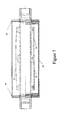
- Figure 7 shows a complete view of the device, with the inner tube 10, the three magnetic rings 11-13 and their respective bridges 31-33, the whole arrangement being located within an outer tube 43 maintained out of contact of bridges 31-33, and forming , with two side flanges 41 and 42 a closed container for preserving and protecting the entire device .
- Figure 8 shows a view of the inner tube 10 with its two connectors 1 and 2 in the example of type % ".
- Figures 9a and 9b illustrate respectively a section and a view of each of the flanges, such as flange 41 , adapted to a rate % inches.
- flange 41 a section and a view of each of the flanges, such as flange 41 , adapted to a rate % inches.
- a skilled person will be able to adapt the structure which was described so as to fit other diameters, e.g. 2 inches , etc....
- Figures 10a and 10b respectively show a sectional view and a view of each of the fittings or couplers/connectors 1 and 2, adapted to a flow of 3 ⁇ 4 inches.
- Figures 11 a and 11 b show respectively a view and a section of the upper bridge 31 for the magnetic connection between the two extreme magnetic rings 12 and 13.
- the bridge 31 shows a deflection D of about 3mm, for example, which avoids contact with the central ring 11.
- the bridge also has an arc of 120 degrees
- the contact bridges are made of a flat strip of copper, with a width of, for example, 3 millimeters, which can be bent for the purpose of achieving the magnetic connection to the magnet.
- the upper bridge ( Fig. 11a, fig 11 b) has to connect the two magnets 12 and 13 being at the ends, and this is achieved with an arc of 120 degrees, for instance.
- Figures 12a and 12b respectively show a sectional view and a section of an embodiment of one of the two lower bridges 32 for the magnetic connection between one of the two ending magnetic rings 12 and 13 with the central magnetic ring 11.
- Figure 12a and 12b show the lower contact bridges which contact one end magnet (12, 13) to the central magnet. This lower bridge is shorter than the upper bridge, thus resulting in an arc of 240 degrees, for instance.
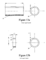
- Figure 13a more particularly illustrates a sectional view and a section of one among the two magnetic core spacers , having the shape of a ring for maintaining the gap between the magnetic rings 12/11 and 13 / 11.
- Figure 13b illustrates more particularly a sectional view and a section of the ending magnetic spacer, also ring shaped, which keeps a predetermined distance between the ending magnetic rings 12 and 13 and the corresponding flanges ( respectively, 41 , 42 ) .
- Figure 14a more particularly illustrates a sectional view and a section of the magnetic central ring 11, being ring-shaped.
- Figure 14b illustrates more specifically a sectional view and a section of one of the two magnetic rings 12 or 13, having the shape of a ring or a ring flange.
- Figure 15a illustrates respectively a sectional view and view of the outer tube 43.
- Figure 15b respectively shows a sectional view and view of the inner tube 10.
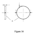
- Figure 16 more specifically illustrates a sectional view and a view of a flange 50 for the fixing and the connection of the - respectively upper and lower - bridges on their respective magnetic rings. That fixing by means of a flange of the constituent flat strip of bridges 31-33 achieves a determined rigidity for the whole structure, and in particular prevents any contact of the upper / lower bridges with the internal wall of outer tube 43.
- Brass may be used as a conductor and also a shielding material, - so as to keep inwardly directed the magnetic field. Brass is known for achieving good electricity conduction and also for creating a shield for containing the magnetic field and strengthening inwards the magnitude of the magnetic field.
- Figures 17a and 17b respectively illustrate a sectional view and a view of another embodiment, for instance adapted to a 2 inch section.
- the second embodiment is adapted to a different flow of fluids; therefore, most dimensions need to be adapted, and generally speaking increased to fit the proper flow. It will be understood by those skilled in the art that changes can be made in dimensions and general shapes and sizes of the components of the device without departing from the spirit and scope of the disclosure.
- the device described above is used for improving the combustion of a mixture of fluid or gaseous hydrocarbon with combustion air.
- the hydrocarbon mixture is flowed within the inner tube 10.
- the core magnetic ring 11 at the center of the inner tube generates a first central axial magnetic field in the tube.
- the first and second end magnetic rings 12 and 13 are maintained at a predetermined distance apart from the central magnetic ring 11 by spacers 21 and 22. These end magnetic rings generate at both ends of the inner tube an axial magnetic field.
- Magnetic connection bridge 31 connects the first and second magnetic rings while avoiding any connection with the central magnetic ring.
- Connection bridges 32 and 33 connect the central magnetic ring and each of the end magnetic rings. The connection bridges allows the creation of a magnetic "path" which is useful for magnetically biasing the combustible molecules. The magnetic bias of the combustible molecules improves combustibility.
- the same interaction between the magnetic field and the combustion air, oxygen, and the water may be performed, for example, prior to its combustion with a hydrocarbon.
- the apparatus can also be used for treating any fluid or mixture of fluids or any gas or mixture of gases requiring a specific physical magnetic change in the structure of some of its constituents.
- fluids such as water, milk and wine and any other liquids could be treated using the apparatus and method of the present disclosure.
Landscapes
- Engineering & Computer Science (AREA)
- Chemical & Material Sciences (AREA)
- Combustion & Propulsion (AREA)
- Mechanical Engineering (AREA)
- General Engineering & Computer Science (AREA)
- Health & Medical Sciences (AREA)
- General Health & Medical Sciences (AREA)
- Toxicology (AREA)
- Organic Chemistry (AREA)
- Chemical Kinetics & Catalysis (AREA)
- Feeding And Controlling Fuel (AREA)
- Physical Or Chemical Processes And Apparatus (AREA)
Applications Claiming Priority (1)
| Application Number | Priority Date | Filing Date | Title |
|---|---|---|---|
| FR1301048A FR3005270B1 (fr) | 2013-05-06 | 2013-05-06 | Dispositif et procede destines a faciliter la combustion de melanges hydrocarbures fluides ou gazeux et de l'air de combustion |
Publications (1)
| Publication Number | Publication Date |
|---|---|
| EP2808530A1 true EP2808530A1 (fr) | 2014-12-03 |
Family
ID=48808278
Family Applications (2)
| Application Number | Title | Priority Date | Filing Date |
|---|---|---|---|
| EP13368017.3A Not-in-force EP2801717B1 (fr) | 2013-05-06 | 2013-06-14 | Dispositif et procédé destinés à faciliter la combustion de mélanges hydrocarbures fluides ou gazeux et de l'air de combustion |
| EP14001579.3A Withdrawn EP2808530A1 (fr) | 2013-05-06 | 2014-05-06 | Appareil et procédé de traitement d'un fluide quelconque ou d'un mélange de fluides ou de tout gaz ou mélange de gaz tel que l'air, et en particulier, un mélange d'hydrocarbures liquides ou gazeux avec de l'air |
Family Applications Before (1)
| Application Number | Title | Priority Date | Filing Date |
|---|---|---|---|
| EP13368017.3A Not-in-force EP2801717B1 (fr) | 2013-05-06 | 2013-06-14 | Dispositif et procédé destinés à faciliter la combustion de mélanges hydrocarbures fluides ou gazeux et de l'air de combustion |
Country Status (4)
| Country | Link |
|---|---|
| US (1) | US20140330052A1 (fr) |
| EP (2) | EP2801717B1 (fr) |
| ES (1) | ES2599261T3 (fr) |
| FR (1) | FR3005270B1 (fr) |
Citations (2)
| Publication number | Priority date | Publication date | Assignee | Title |
|---|---|---|---|---|
| US4933151A (en) * | 1988-12-16 | 1990-06-12 | Song Ben C | Device for magnetically treating hydrocarbon fuels |
| EP0544395A2 (fr) * | 1991-11-28 | 1993-06-02 | T.L.H. Brothers Sdn. Bhd. | Dispositif pour le traitement magnétique de liquides, gaz ou solides |
Family Cites Families (2)
| Publication number | Priority date | Publication date | Assignee | Title |
|---|---|---|---|---|
| JPH07217507A (ja) * | 1994-02-02 | 1995-08-15 | Miyazaki Hiroyuki | 給送燃料油改質装置 |
| TW200742797A (en) * | 2006-05-04 | 2007-11-16 | Jin-Lang Wang | Fuel economizer |
-
2013
- 2013-05-06 FR FR1301048A patent/FR3005270B1/fr not_active Expired - Fee Related
- 2013-06-14 EP EP13368017.3A patent/EP2801717B1/fr not_active Not-in-force
- 2013-06-14 ES ES13368017.3T patent/ES2599261T3/es active Active
-
2014
- 2014-05-06 EP EP14001579.3A patent/EP2808530A1/fr not_active Withdrawn
- 2014-05-06 US US14/270,829 patent/US20140330052A1/en not_active Abandoned
Patent Citations (2)
| Publication number | Priority date | Publication date | Assignee | Title |
|---|---|---|---|---|
| US4933151A (en) * | 1988-12-16 | 1990-06-12 | Song Ben C | Device for magnetically treating hydrocarbon fuels |
| EP0544395A2 (fr) * | 1991-11-28 | 1993-06-02 | T.L.H. Brothers Sdn. Bhd. | Dispositif pour le traitement magnétique de liquides, gaz ou solides |
Also Published As
| Publication number | Publication date |
|---|---|
| EP2801717A1 (fr) | 2014-11-12 |
| EP2801717B1 (fr) | 2016-07-20 |
| FR3005270A1 (fr) | 2014-11-07 |
| FR3005270B1 (fr) | 2015-04-24 |
| US20140330052A1 (en) | 2014-11-06 |
| ES2599261T3 (es) | 2017-01-31 |
Similar Documents
| Publication | Publication Date | Title |
|---|---|---|
| US5348050A (en) | Magnetic fluid treatment device | |
| CN107921441B (zh) | 用于顺磁性及反磁性物质的过滤器 | |
| CN103502620B (zh) | 用于优化内燃机的方法 | |
| AU2003250388A1 (en) | Magnetic conditioning of fluids and gases and apparatus therefor | |
| US20110005628A1 (en) | Magnetohydrodynamic Fluid Conditioner | |
| JPS63502729A (ja) | 水処理装置 | |
| US6707362B1 (en) | Method and apparatus for focusing a magnetic field to treat liquids | |
| US20120067802A1 (en) | In-line fuel conditioner | |
| Chen et al. | Effects and characteristics of AC interference on parallel underground pipelines caused by an AC electrified railway | |
| Roth et al. | A High‐gradient magnetic separator for highly viscous process liquors in industrial biotechnology | |
| EP2808530A1 (fr) | Appareil et procédé de traitement d'un fluide quelconque ou d'un mélange de fluides ou de tout gaz ou mélange de gaz tel que l'air, et en particulier, un mélange d'hydrocarbures liquides ou gazeux avec de l'air | |
| Mishchenko et al. | Global linear gyrokinetic particle-in-cell simulations including electromagnetic effects in shaped plasmas | |
| Popoli et al. | Reduction in the electromagnetic interference generated by AC overhead power lines on buried metallic pipelines with screening conductors | |
| TW457355B (en) | An apparatus for treating a fluid by applying a magnetic field | |
| Iwabuchi et al. | Influence of sodium carbonate on decomposition of formic acid by pulsed discharge plasma inside bubble in water | |
| US7767081B2 (en) | Magnetic fuel conditioner | |
| WO2017029568A1 (fr) | Appareil et procédé pour le contrôle microbiologique de fluides au moyen de champs électriques et magnétiques produits à partir d'un courant électrique alternatif basse tension et basse fréquence | |
| US20160167986A1 (en) | Systems and methods for reducing corrosion in a reactor system using electromagentic fields | |
| JP2009072725A (ja) | 流体の磁気処理装置 | |
| CN104857765A (zh) | 一种经改良升级创新的电磁过滤器 | |
| CN204767759U (zh) | 一种经改良升级创新的电磁过滤器 | |
| US20110100879A1 (en) | Improvements in or relating to filters | |
| JP2011167583A (ja) | 配管内流体の磁気活性方法及び配管取付用磁気活性装置 | |
| US20150191373A1 (en) | Apparatus for Establishing Electrodes in a Liquid | |
| RU188954U1 (ru) | Автономный электромагнитный индуктор скважинный |
Legal Events
| Date | Code | Title | Description |
|---|---|---|---|
| PUAI | Public reference made under article 153(3) epc to a published international application that has entered the european phase |
Free format text: ORIGINAL CODE: 0009012 |
|
| 17P | Request for examination filed |
Effective date: 20140506 |
|
| AK | Designated contracting states |
Kind code of ref document: A1 Designated state(s): AL AT BE BG CH CY CZ DE DK EE ES FI FR GB GR HR HU IE IS IT LI LT LU LV MC MK MT NL NO PL PT RO RS SE SI SK SM TR |
|
| AX | Request for extension of the european patent |
Extension state: BA ME |
|
| STAA | Information on the status of an ep patent application or granted ep patent |
Free format text: STATUS: THE APPLICATION IS DEEMED TO BE WITHDRAWN |
|
| 18D | Application deemed to be withdrawn |
Effective date: 20150604 |