EP2808553B1 - Moteur électrique avec roue de ventilateur - Google Patents
Moteur électrique avec roue de ventilateur Download PDFInfo
- Publication number
- EP2808553B1 EP2808553B1 EP14169375.4A EP14169375A EP2808553B1 EP 2808553 B1 EP2808553 B1 EP 2808553B1 EP 14169375 A EP14169375 A EP 14169375A EP 2808553 B1 EP2808553 B1 EP 2808553B1
- Authority
- EP
- European Patent Office
- Prior art keywords
- fan wheel
- electric motor
- axis
- cover part
- motor according
- Prior art date
- Legal status (The legal status is an assumption and is not a legal conclusion. Google has not performed a legal analysis and makes no representation as to the accuracy of the status listed.)
- Not-in-force
Links
Images

Classifications
-
- F—MECHANICAL ENGINEERING; LIGHTING; HEATING; WEAPONS; BLASTING
- F04—POSITIVE - DISPLACEMENT MACHINES FOR LIQUIDS; PUMPS FOR LIQUIDS OR ELASTIC FLUIDS
- F04D—NON-POSITIVE-DISPLACEMENT PUMPS
- F04D29/00—Details, component parts, or accessories
- F04D29/26—Rotors specially for elastic fluids
- F04D29/28—Rotors specially for elastic fluids for centrifugal or helico-centrifugal pumps for radial-flow or helico-centrifugal pumps
- F04D29/281—Rotors specially for elastic fluids for centrifugal or helico-centrifugal pumps for radial-flow or helico-centrifugal pumps for fans or blowers
-
- F—MECHANICAL ENGINEERING; LIGHTING; HEATING; WEAPONS; BLASTING
- F04—POSITIVE - DISPLACEMENT MACHINES FOR LIQUIDS; PUMPS FOR LIQUIDS OR ELASTIC FLUIDS
- F04D—NON-POSITIVE-DISPLACEMENT PUMPS
- F04D29/00—Details, component parts, or accessories
- F04D29/70—Suction grids; Strainers; Dust separation; Cleaning
- F04D29/701—Suction grids; Strainers; Dust separation; Cleaning especially adapted for elastic fluid pumps
- F04D29/706—Humidity separation
-
- F—MECHANICAL ENGINEERING; LIGHTING; HEATING; WEAPONS; BLASTING
- F05—INDEXING SCHEMES RELATING TO ENGINES OR PUMPS IN VARIOUS SUBCLASSES OF CLASSES F01-F04
- F05D—INDEXING SCHEME FOR ASPECTS RELATING TO NON-POSITIVE-DISPLACEMENT MACHINES OR ENGINES, GAS-TURBINES OR JET-PROPULSION PLANTS
- F05D2250/00—Geometry
- F05D2250/70—Shape
-
- F—MECHANICAL ENGINEERING; LIGHTING; HEATING; WEAPONS; BLASTING
- F05—INDEXING SCHEMES RELATING TO ENGINES OR PUMPS IN VARIOUS SUBCLASSES OF CLASSES F01-F04
- F05D—INDEXING SCHEME FOR ASPECTS RELATING TO NON-POSITIVE-DISPLACEMENT MACHINES OR ENGINES, GAS-TURBINES OR JET-PROPULSION PLANTS
- F05D2260/00—Function
- F05D2260/60—Fluid transfer
- F05D2260/602—Drainage
Definitions
- the invention relates to an electric motor according to the features of the preamble of claim 1.
- Blower wheels which are mounted on a rotor of an electric motor are known. These are driven by the electric motor, wherein the impeller is further preferably rotatably secured to the rotor axis of the electric motor.
- an air flow is achieved via the rotating fan wheel, in particular for cooling the electric motor, more preferably in the arrangement of the electric motor and fan wheel, for example in a vacuum cleaner or the like, for building up a suction air flow.
- the impeller blades are covered by a co-rotating ceiling part. This essentially serves for the targeted direction of flow in the area of the fan wheel, so on, in particular for achieving a radial fan.
- the air is preferably sucked in the axial direction, more preferably centrally of the impeller, more preferably passing through a corresponding opening of the ceiling portion, and passed at least according to the arrangement of the impeller blades radially outward.
- An electric motor with such an impeller is, for example, from the DE 10 2008 014 624 A1 known.
- the invention is concerned with the task of specifying an electric motor with impeller, which is in particular further improved fluidically.
- the ceiling part has a parallel or substantially parallel to a blower bottom floor extending ceiling portion that a radially free end portion of the ceiling portion is surrounded by an annular receiving space, such that at one Inside the ceiling portion funded liquid is supplied into the receiving space, and that a receiving space bottom of the receiving space extends in a plane transverse to the axis of rotation extending farther to the ceiling portion than the circumferential free edge of the free end portion.
- the radially outwardly directed opening regions between the impeller blades are at least partially covered radially on the outside, so that in this region at least a partial deflection of the air flow and possibly entrained by the air flow particles results.
- the cover part extends from an axial overlap of the impeller blades into an at least partially radial overlap, whereby a ceiling part with a radially outwardly facing end edge edges of the impeller blades overlapping circumferential wall area results.
- the cover part radially covers the impeller blades in the inflow direction of the air or in the direction of extent of the axis up to a given in this direction end of the impeller blades. Accordingly, the ceiling part extends from an axial overlap of the impeller blades into an at least partially radial overlap, which results in a preferred embodiment, a ceiling part with one, the radially outwardly facing end edges of the impeller blades overlapping, circumferential wall area.
- the cover part radially covers the impeller blades in the inflow direction of the air or in the direction of extent of the axis to a given in this direction end of the impeller blades.
- the cover part extends at least in a region comprising the impeller blades radially outward, more preferably with respect to a cutting plane extending in the axial direction of the impeller at least approximately parallel to the inflow direction of the air, further approximately parallel to the axis of rotation of the impeller. More preferably, such, the impeller blades radially outwardly overlapping portion of the ceiling portion at an acute angle to the impeller axis, accordingly oriented at an acute angle along an axis parallel.
- the ceiling part further preferably extends with the fan blades radially outwardly surrounding portion at least up to an axial end of the impeller blades, in particular an axial end the radially outward preferred free end edge of the impeller blades, which end is more preferably opposite to the covered by the ceiling part axial end. More preferably, this section of the ceiling part extends beyond the axial end, in particular the free end edge of the edge of the impeller blades, more preferably also via a, the impeller blades carrying bottom part of the impeller.
- the impeller blades are formed in a further preferred embodiment in a radial overlap area with the ceiling part at least over a part of the given length in the axial direction with respect to a radially outer end of an impeller with radial clearance to an inner surface of the ceiling part.
- a gap portion in particular a circumferential gap portion with respect to the axis of rotation between the radially outer ends of the impeller blades and the facing inner surface of the ceiling portion.
- the ceiling part in a radial covering area to the fan wheel blades, extends widening radially outward in the direction of the axis. It results in this respect preferred - with respect to a vertical section through the impeller - an example. Conical expansion. In preferably parallel to the rotational axis of the impeller extending free end edge edges of the impeller blades results here more preferably an example. Wedge-shaped enlargement of the gap between the edge edge edge and facing inner surface of the ceiling part.
- the radial extension over the length of the axis is different with inclusion Angle formed with the axis.
- the area of the ceiling part formed in radial overlap with the impeller blades is rectilinear with respect to a cross-section, evenly spaced from the axis, while an adjoining, preferably free-terminating end portion of the ceiling part encloses an altered acute angle with respect to the axis , This end region further preferably extends below the impeller, in particular in the region of a formed diffuser.
- the radially free end region of the ceiling part preferably encloses a larger angle with the axis than a middle region of the ceiling part, in particular as a region formed in radial overlap with the fan wheel blades.
- this range preferably includes an acute angle of 5 ° to 30 °, more preferably 10 ° to 20 °, while the free end portion of the ceiling portion preferably includes an angle of 30 ° to 75 °, more preferably 45 ° to 60 ° to the rotation axis ,
- the ceiling portion extends in a preferred embodiment in the direction of the axis of the impeller blades by an amount beyond, which preferably corresponds to half or more of the axial height of the impeller blades, more preferably half or more of the largest axial height of the impeller blades in the course of their radial extent. More preferably, the ceiling part extends up to a three times the axial height of the impeller blades in the direction of the axis on the impeller blades.
- a radially free end region of the ceiling part passes through a motor housing of the electric motor in a plane transverse to the axis.
- enforcement of a partial region of the motor housing is furthermore preferably provided, more preferably such that the co-rotating ceiling part at least in the axial direction via the fan wheel blades Furthermore, extending radially outward area is still covered by a portion of the motor housing.
- the radially free end region of the cover part in particular an end region of the ceiling part which extends beyond the fan wheel blades in the direction of the axes, is surrounded by the annular receiving space, such that optionally conveyed liquid is supplied to the receiving space on an inner side of the ceiling part.
- any fluid particles entrained with the air flow or solid particles are first, in particular due to the design of the ceiling part, further derived from the resulting centrifugal forces along the inside of the ceiling part in the direction of the free end region and delivered into the receiving space adjoining this end region.
- the end region can end here with a small distance to the receiving space.
- the end region extends into the receiving space.
- the outlet opening in particular a central axis of the outlet opening, extends oriented parallel to the axis of rotation of the impeller.
- this outlet opening can in the Receiving room supplied liquid or the like can be specifically removed.
- the outlet opening is associated with a bottom of the receiving space, which latter is designed in a trough-like manner in a preferred embodiment with respect to a cross section.
- the outlet opening is associated with a Abteilausformung, which protrudes at a distance radially inward to an outer wall of the receiving space and the outlet opening.
- this Abteilausformung is formed out of a radially outer annular wall of the receiving space. Due to the stagnation-like Abteilausformung the liquid phase is directed to the outlet opening. As a result, a multiple orbiting of the liquid phase is counteracted, which would otherwise lead to a reduction of the spin energy. Due to the selected measure, the system can be used regardless of location.
- the compartment formation ends projecting freely in the projection in a projection corresponding to a center axis of the outlet opening.
- the compartment formation preferably extends from an edge of the outlet opening over 20% to 80% of the largest cross-sectional dimension of the outlet opening freely into the outlet opening.
- the ceiling part is preferably covered by a fixed motor housing section. More preferably, the ceiling part is completely covered by the fixed motor housing section rotates accordingly in the operation of the Blower in a hiding position.
- the motor housing portion in cooperation with areas of the ceiling part form a barrier against in particular liquids between the ceiling part and the motor housing portion. In a preferred embodiment, this is achieved by a labyrinthine interaction of the ceiling part and the motor housing section.
- the ceiling part preferably forms, at least in a covering area, seen transversely to the axis, to the electric motor or motor housing, in cooperation with the motor housing, a radially directed channel between an upper side of the motor housing and an underside of the ceiling part.
- a radially directed channel between an upper side of the motor housing and an underside of the ceiling part.
- the channel is in this case further preferably formed circumferentially with respect to the axis. Essentially projects into this channel, the free end portion of the ceiling part, which includes a larger angle with the axis.
- the upper side of the motor housing and the underside of the cover part extend at least approximately parallel, so that the channel formed thereby has a constant extent over its entire (tendency) radial length.
- the channel width of the channel corresponds in a preferred embodiment a third or less of the given radially outside at the free end free height of the impeller blades. More preferably, the width corresponds to 0.2 to 1 times the radially outside given free height of the impeller blades. In a further embodiment, the gap dimension selected (width of the channel) corresponds to about 1% to 5%, more preferably about 2% of the maximum diameter of the channel considered in a plane oriented transversely to the axis.
- the given in the flow direction length of the channel preferably corresponds to 0.1 to 0.3 times the diameter of the impeller at the free end of an impeller blade, here possibly based on the largest diameter of the impeller if it changes over the axial height of the impeller blades ,
- the gap length of the channel given thereby corresponds to approximately 5% to 15%, more preferably approximately 9% of the largest channel diameter with respect to the axis.
- the length of the channel at least approximately corresponds to the given in cross-section length of the region of the ceiling part, which includes a larger acute angle with the axis.
- the liquid phase is optionally conveyed away in a preferred embodiment with a partial air flow against gravity.
- This partial air flow results from the total air flow, which is constructed by the activated impeller.
- the partial air flow in this case preferably corresponds to up to 10% of the intake air volume and is preferably guided through the channel and the receiving space to the outlet opening, with the preferred support of the removal of the liquid phase from the receiving space.
- the ranges and / or ranges of values or multiple ranges given above also include all intermediate values, in particular in 1/10 increments of the respective dimension, if necessary also dimensionless, in particular 1.01 times etc., on the one hand for delimitation the aforementioned range limits from below and / or above, alternatively or additionally, but also with regard to the disclosure of one or more singular values from the respectively specified range.
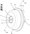
- an electric motor 1 with an impeller 3 arranged on a rotor shaft 2 and a guide stage in the form of a diffuser 4.
- the impeller 3 is rotatably mounted on the rotor shaft 2 and is rotated about this, wherein the rotor shaft 2 rotatably with a rotor of the Electric motor 1 is connected.
- the rotor interacts with a stator, not shown, of the electric motor.
- the diffuser 4 is not rotatably mounted in a, the electric motor 1 substantially receiving the motor housing 5.
- the impeller 3 further has first an essentially transverse to the axis of rotation x aligned impeller bottom 6. This is in particular hub-thickened in the central region, for rotationally fixed connection to the rotor shaft. 2
- impeller blades 7 are formed on the impeller bottom 6, in particular facing away from the electric motor 1. These are further preferred in particular in the embodiment of the impeller 3 from a plastic injection molded part in one piece and of the same material formed with the impeller bottom 6.
- the Fan blades 7 extend substantially from radially inward to radially outward, in particular up to the edge of the fan wheel base 6, more preferably in this case with respect to a floor plan or a projection on the impeller bottom 6 curved in a circular segment.
- the impeller blades 7 preferably have a constant height h over their radial longitudinal extent. This preferably corresponds to about 0.1 to 0.3 times the impeller diameter.
- the impeller blades 7 are further preferably at least largely covered on the side facing away from the impeller bottom 6 by a ceiling part 8.
- This ceiling part 8 initially has a parallel or substantially parallel to the blower bottom 6 extending ceiling section 9, in which a central inlet opening 10 is left.
- the ceiling part 8 is rotatably connected to the impeller 3, rotates accordingly in operation of the electric motor 1 with.
- the ceiling part 8 further extends at least in radial overlap to the radially outer ends of the fan wheel blades 7, more preferably starting from the ceiling section 9 to beyond the plane of the fan wheel base 6 addition.
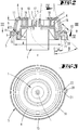
- This radial extension 11 extends with respect to a cross section according to FIG. 2 at an acute angle ⁇ of 5 ° to 15 °, more preferably about 10 ° to an axis parallel. More preferably, the radial extension 11 extends from the ceiling portion 9 to above a level on the impeller bottom 6 addition, which corresponds to about 0.5 to 1 times the impeller blade height h.
- the radial extension 11 extends in cross section starting from the ceiling portion 9 towards the free end region radially widening.
- the radial extension 11 merges into a free end region 12.
- This is, as well as the radial extension 11, in cross section according to FIG. 2 formed elongated rectilinearly, in this case more preferably an angle ⁇ of 40 ° to 60 °, more preferably about 45 ° to 50 ° to an axis parallel enclosing.
- the free end region 12 extends radially widening starting from the radial extension 11 in the direction of the free end.
- the length 1 of the free end portion 12 in cross section preferably corresponds to 0.8 to 1.2 times the impeller blade height h.
- the ceiling part 8 with its radial extension 11 and the free end area 12 is designed to be rotationally symmetrical with respect to the axis of rotation x.
- the free end region 12, moreover also the section of the radial extension 11 projecting beyond the blower bottom 6, are arranged in a preferred embodiment in radial overlap with the diffuser 4, whereby the diffuser 4 can directly also be part of the motor housing 5.
- the free end portion 12 facing surface of the Motor housing 5 preferably parallel to the facing inner surface of the free end portion 12, whereby substantially the channel 13 extends at an acute angle corresponding to the angle ⁇ sloping radially outward.
- the resultant gap height in the channel 13 or the width b given thereby transversely to the longitudinal extension of the free end region 12 preferably corresponds to approximately 2% of the largest diameter d of the channel 13
- FIG. 2 considered length of the channel 13 preferably corresponds to the length of the free end portion 12, more preferably about 9% of the diameter d of the channel thirteenth
- the channel 13 is designed to be open both radially inward in the direction of the impeller 3 receiving space, as well as circumferentially radially outward. This is followed by the channel 13 an annular, correspondingly circumferential receiving space 14 at.
- Whose receiving space floor extends in a direction transverse to the axis of rotation x extending plane, which is further spaced from the ceiling portion 9 than the circumferential free edge of the free end portion 12th
- the receiving space 14 is limited in cross-section on the one hand by the motor housing 5 and an extension of the diffuser 4, further by the hereby preferably integrally formed and uniform material receiving space floor 15 and more preferably by a foot portion of a further preferably fixed motor housing portion 16.
- This motor housing portion 16 cup-like over the It is further preferred with the other motor housing 5 and / or the diffuser 4 and rotatably connected thereto to the electric motor 1.
- the motor housing portion 16 further preferably extends the free end portion 12, the radial extension 11 as well as the ceiling portion 9 each substantially (with respect to the inner wall) extending parallel thereto covering, more preferably in vertical projection to the inlet opening 10 of the ceiling part 8 and in the motor housing portion 16, a corresponding inlet opening 17 is formed.
- the cover part 8 engages with preferably two concentric with each other, the cover part upper side shaped ribs 18 in correspondingly positioned grooves 19 of the motor housing portion 16 a.
- an outlet opening 20 is further preferably provided, with a preferably circular opening edge edge.
- the outlet channel 21 is open in the representations to the environment. It may continue to connect to the outlet 21, a hose or the like.
- a stowage wall-shaped Abteilausformung 22 is provided.
- This Abteilausformung 22 is preferably made of the radially outer wall of the receiving space 14, protrudes here with the free end radially inward - with respect to the axis of rotation x - before, so that the free end portion a radial distance to the outer wall or to an extension of Outside wall occupies.
- the compartment formation 22 projects freely into the outlet opening 20, more preferably approximately in the area of an outlet opening central axis, with a preferred diameter of the outlet opening 20 that is at least 1.5 times the radial extent of the receiving room floor 15 corresponds.
- the radial outer wall of the receiving space 14 extends here correspondingly different from the otherwise concentric alignment with the axis of rotation x (see. FIG. 3 ).
- the liquid phase is thrown off from the co-rotating, in the flow direction twice conically radially expanded portion 11 into the receiving space 14, wherein the impressed swirl energy is used to promote the liquid phase at the periphery of the receiving space 14 along the outlet opening 20.
- the liquid phase is deflected by the counter to the flow direction within the receiving space 14 directed Abteilausformung 22 to the outlet opening 20.
- a multiple orbiting of the liquid phase within the receiving space 14 is counteracted.
- a multiple circling would lead to a reduction of the swirl energy, whereby the desired position independence of the system would be disturbed.
- the liquid phase with a relatively small partial air flow (preferably less than 10% of the total sucked Air quantity in the region of the inflow opening 10) possibly also transported away against gravity.
- the twist is kept so high by the co-rotating cover part 8 that water is prevented from flowing back in the direction of the diffuser 4 along the motor housing side wall of the channel 13.
- the receiving space 14 is formed spirally with a further preferred embodiment. Further, distributed over the circumference of the receiving space 14 a plurality of outlet openings 20 may be assigned, so for example, two, three, four or more, which may also be radially aligned with respect to the axis of rotation x, beyond preferably also tangentially.
- the bladed diffuser 4 provided axially behind the fan wheel bottom 6 has an axial distance to the ceiling section 9 which is approximately 0.2 times the fan wheel diameter. It is also preferable to provide an overlap of diffuser 4 and co-rotating cover part 8 present in the axial direction, which overlap preferably corresponds to approximately 0.1 times the fan wheel diameter.
Landscapes
- Engineering & Computer Science (AREA)
- Mechanical Engineering (AREA)
- General Engineering & Computer Science (AREA)
- Structures Of Non-Positive Displacement Pumps (AREA)
Claims (15)
- Moteur électrique (1) avec un rotor et une roue de ventilateur (3), dans lequel la roue de ventilateur (3) présente un axe de roue de ventilateur (x), un fond de roue de ventilateur (6) orienté sensiblement transversal à l'axe de rotation et des pales de roue de ventilateur (7) couvertes par un élément de couverture (8) en co-rotation, dans lequel en outre les pales de roue de ventilateur (7) présentent une extension dans la direction axiale et l'élément de couverture (8) couvre radialement à l'extérieur dans la direction de l'axe (x) la moitié ou plus de l'extension axiale des pales de roue de ventilateur (7), dans lequel l'élément de couverture (8) présente une portion de couverture (9) s'étendant parallèle ou sensiblement parallèle à un fond de roue de ventilateur (6) et dans laquelle subsiste centralement une ouverture d'admission (10), caractérisé en ce qu'une région d'extrémité radialement libre (12) de l'élément de couverture (8) est entourée par un espace de réception (14) de forme annulaire de manière à ce que du liquide amené à un côté intérieur de l'élément de couverture (8) soit introduit dans l'espace de réception (14) et qu'un fond (15) de l'espace de réception (14) s'étende dans un plan transversal à l'axe de rotation (x) lequel est plus espacé de la portion de couverture (9) que le bord libre périphérique de la région d'extrémité libre (12).
- Moteur électrique selon la revendication 1, caractérisé en ce que l'élément de couverture (8) couvre radialement les pales de roue de ventilateur (7) dans la direction d'admission de l'air ou dans la direction d'extension de l'axe (x) jusqu'à au-delà d'une extrémité, définie dans cette direction, des pales de roue de ventilateur (7) .
- Moteur électrique selon la revendication 1, caractérisé en ce que dans une zone de recouvrement radiale avec l'élément de couverture (8), les pales de roue de ventilateur (7) sont formées avec un espace libre par rapport à une surface intérieure de l'élément de couverture (8) au moins sur une partie de la hauteur (h) définie en direction axiale en référence à une extrémité radialement extérieure d'une pale de roue de ventilateur (7).
- Moteur électrique selon l'une des revendications précédentes, caractérisé en ce que dans une zone de recouvrement radiale des pales de roue de ventilateur (7), l'élément de couverture (8) s'étend dans la direction de l'axe (x) en s'élargissant radialement vers l'extérieur.
- Moteur électrique selon la revendication 4, caractérisé en ce que, en référence à une section transversale, l'extension radiale (11) est formée le long de l'axe (x) en ayant différents angles (α, β) avec l'axe (x).
- Moteur électrique selon la revendication 5, caractérisé en ce qu'une extrémité radiale libre (12) de l'élément de couvercle (8) présente un angle (β) avec l'axe (x) qui est supérieur à celui d'une zone médiane.
- Moteur électrique selon l'une des revendications précédentes, caractérisé en ce que l'élément de couverture (8) s'étend dans la direction de l'axe (x) au-delà des pales de roue de ventilateur (7) d'une distance correspondant à la moitié ou plus de la hauteur axiale (h) des pales de roue de ventilateur (7).
- Moteur électrique selon la revendication 7, caractérisé en ce que l'élément de couverture (8) s'étend dans la direction de l'axe (x) au-delà des pales de roue de ventilateur (7) d'une distance correspondant à jusqu'à 3 fois la hauteur axiale (h) des pales de roue de ventilateur (7).
- Moteur électrique selon l'une des revendications précédentes, caractérisé en ce qu'une région d'extrémité radialement libre (12) de l'élément de couverture (8) traverse, dans un plan disposé transversalement à l'axe (x), un boîtier de moteur (5) du moteur électrique.
- Moteur électrique selon l'une des revendications précédentes, caractérisé en ce que l'espace de réception (14) comprend au moins un orifice de sortie (20) s'étendant dans la direction de l'axe (x) .
- Moteur électrique selon la revendication 10, caractérisé en ce qu'est associé à l'orifice de sortie (20) un façonnement séparateur (22) lequel fait saillie en étant radialement espacé vers l'intérieur par rapport à une paroi extérieure de l'espace de réception (14) ou de l'orifice de sortie (20).
- Moteur électrique selon la revendication 11, caractérisé en ce que, dans une projection selon un axe central de l'orifice de sortie, le façonnement séparateur (22) se termine en porte-à-faux dans l'orifice d'évacuation (20).
- Moteur électrique selon l'une des revendications précédentes, caractérisé en ce que l'élément de couverture (8) est recouvert par une partie fixe de boîtier de moteur (16) et/ou en ce que de préférence, au moins dans une zone de recouvrement avec le moteur électrique (1) ou boîtier de moteur (5) vue transversalement à l'axe (x), l'élément de couverture (8) forme en coopération avec le boîtier de moteur (5) un canal (13) orienté radialement entre un côté supérieur du boîtier de moteur (5) et un côté inférieur de l'élément de couverture (8).
- Moteur électrique selon la revendication 13, caractérisé en ce qu'une largeur (b) du canal (13) définie perpendiculairement à la direction d'écoulement du canal (13), correspond à un tiers ou moins de la hauteur libre (h) des pales de roue de ventilateur (7) définie radialement à l'extérieur.
- Moteur électrique selon la revendication 14, caractérisé en ce que la largeur (b) du canal (13) correspond à 0,2 à 1,0 fois la hauteur libre (h) des pales de roue de ventilateur (7) définie radialement à l'extérieur et/ou en ce que, de préférence, la longueur (1) de canal (13) définie dans la direction d'écoulement correspond à 0,1 à 0,3 fois le diamètre de la roue de ventilateur à l'extrémité libre d'une pale de roue de ventilateur (7), le cas échéant en référence au plus grand diamètre.
Applications Claiming Priority (1)
| Application Number | Priority Date | Filing Date | Title |
|---|---|---|---|
| DE102013105536.2A DE102013105536A1 (de) | 2013-05-29 | 2013-05-29 | Gebläserad |
Publications (3)
| Publication Number | Publication Date |
|---|---|
| EP2808553A2 EP2808553A2 (fr) | 2014-12-03 |
| EP2808553A3 EP2808553A3 (fr) | 2014-12-10 |
| EP2808553B1 true EP2808553B1 (fr) | 2017-11-22 |
Family
ID=50774652
Family Applications (1)
| Application Number | Title | Priority Date | Filing Date |
|---|---|---|---|
| EP14169375.4A Not-in-force EP2808553B1 (fr) | 2013-05-29 | 2014-05-22 | Moteur électrique avec roue de ventilateur |
Country Status (5)
| Country | Link |
|---|---|
| EP (1) | EP2808553B1 (fr) |
| JP (1) | JP2014231836A (fr) |
| CN (1) | CN104214134B (fr) |
| DE (1) | DE102013105536A1 (fr) |
| ES (1) | ES2654626T3 (fr) |
Families Citing this family (5)
| Publication number | Priority date | Publication date | Assignee | Title |
|---|---|---|---|---|
| DE102015213006A1 (de) * | 2015-07-10 | 2017-01-12 | Mahle International Gmbh | Gebläseanordnung |
| EP3833875B1 (fr) * | 2018-11-23 | 2023-07-26 | Ebm-Papst St. Georgen Gmbh & Co. Kg | Ventilateur radial |
| WO2020253093A1 (fr) * | 2019-06-20 | 2020-12-24 | 苏州工业园区星德胜电机有限公司 | Ventilateur à double usage sec et humide à haut rendement |
| DE102020118595A1 (de) | 2020-07-14 | 2022-01-20 | Alfred Kärcher SE & Co. KG | Saug-Reinigungsgerät und Verfahren zum Betreiben eines Saug-Reinigungsgeräts |
| DE102024126881A1 (de) * | 2024-09-19 | 2026-03-19 | Zf Cv Systems Global Gmbh | Gebläse für eine Brennstoffzellenanordnung |
Family Cites Families (19)
| Publication number | Priority date | Publication date | Assignee | Title |
|---|---|---|---|---|
| JPS5353672U (fr) * | 1976-10-11 | 1978-05-09 | ||
| JPS57137689A (en) * | 1981-02-18 | 1982-08-25 | Matsushita Electric Ind Co Ltd | Blower |
| JPS61101698U (fr) * | 1984-12-10 | 1986-06-28 | ||
| JPH0353693Y2 (fr) * | 1985-04-01 | 1991-11-25 | ||
| JPS63192988A (ja) * | 1987-02-05 | 1988-08-10 | Tokyo Electric Co Ltd | 電動送風機 |
| JPS63215897A (ja) * | 1987-03-03 | 1988-09-08 | Matsushita Electric Ind Co Ltd | 電動送風機 |
| JPH08219091A (ja) * | 1995-02-17 | 1996-08-27 | Matsushita Electric Ind Co Ltd | 電動ポンプ装置 |
| JP4419204B2 (ja) * | 1999-02-04 | 2010-02-24 | パナソニック株式会社 | 電動送風機 |
| JP4669165B2 (ja) * | 2001-07-03 | 2011-04-13 | 株式会社クラコ | オイルミスト除去装置 |
| US7191613B2 (en) * | 2002-05-08 | 2007-03-20 | Lg Electronics Inc. | Turbo fan and air conditioner having the same applied thereto |
| JP3984598B2 (ja) * | 2004-02-20 | 2007-10-03 | 株式会社クラコ | ファン装置 |
| DE102005047457A1 (de) * | 2004-10-01 | 2006-04-13 | Wss Gmbh | Vorrichtung zur Garraum-Klimareinigung in Form eines Lüfterrades |
| JP4700414B2 (ja) * | 2005-06-02 | 2011-06-15 | 本田技研工業株式会社 | 空冷内燃機関用多翼ファン |
| DE112008000850T5 (de) * | 2007-04-05 | 2010-03-04 | Borgwarner Inc., Auburn Hills | Ringlüfter- und Lüfterkragen-Luftführungssystem |
| DE102007019264A1 (de) * | 2007-04-24 | 2008-11-06 | Man Turbo Ag | Filtervorrichtung |
| DE102008014642A1 (de) | 2008-03-17 | 2009-09-24 | Linde Material Handling Gmbh | Flurförderzeug |
| DE102008014624A1 (de) | 2008-03-17 | 2009-09-24 | Vorwerk & Co. Interholding Gmbh | Elektromotor |
| EP2143958A1 (fr) * | 2008-07-07 | 2010-01-13 | Josip Pavetic | Ventilateur installé dans un tuyau |
| JP5600877B2 (ja) * | 2009-02-06 | 2014-10-08 | パナソニック株式会社 | 電動送風機 |
-
2013
- 2013-05-29 DE DE102013105536.2A patent/DE102013105536A1/de not_active Withdrawn
-
2014
- 2014-05-22 EP EP14169375.4A patent/EP2808553B1/fr not_active Not-in-force
- 2014-05-22 ES ES14169375.4T patent/ES2654626T3/es active Active
- 2014-05-26 JP JP2014108396A patent/JP2014231836A/ja active Pending
- 2014-05-29 CN CN201410362783.8A patent/CN104214134B/zh not_active Expired - Fee Related
Non-Patent Citations (1)
| Title |
|---|
| None * |
Also Published As
| Publication number | Publication date |
|---|---|
| JP2014231836A (ja) | 2014-12-11 |
| ES2654626T3 (es) | 2018-02-14 |
| CN104214134A (zh) | 2014-12-17 |
| DE102013105536A1 (de) | 2014-12-04 |
| EP2808553A2 (fr) | 2014-12-03 |
| EP2808553A3 (fr) | 2014-12-10 |
| CN104214134B (zh) | 2018-04-10 |
Similar Documents
| Publication | Publication Date | Title |
|---|---|---|
| EP2677174B1 (fr) | Roue de ventilateur et moteur électrique | |
| EP2875718B1 (fr) | Appareil de travail manuel doté d'un tube de soufflage | |
| DE102009039783B4 (de) | Zentrifugalgebläse | |
| DE69023699T2 (de) | Selbstansaugende Kreiselpumpe. | |
| DE4335686B4 (de) | Gebläse | |
| DE112012002419B4 (de) | Zentrifugalgebläse und mit demselben versehene Fahrzeugklimaanlage | |
| DE3315477C2 (de) | Staubabscheider | |
| DE19946187A1 (de) | Transportables Gebläse für fliessfähige Medien | |
| EP2808553A2 (fr) | Roue de ventilateur | |
| CH640126A5 (de) | Nassreinigungs-sauggeblaesevorrichtung. | |
| EP0215476B1 (fr) | Meuleur rotatif avec dispositif d'aspiration de la poussière | |
| DE2035380A1 (de) | Staubsauger mit einem von einem Elektro motor angetriebenen Sauggeblase | |
| DE102015210647A1 (de) | Zentrifugalgebläse | |
| EP2740942A2 (fr) | Ventilateur médical ou dentaire | |
| DE2950060C2 (fr) | ||
| AT514319B1 (de) | Unterwasserreiniger | |
| DE2750967B1 (de) | Vorrichtung zum Verbinden eines Antriebsmotors und einer Pumpe | |
| EP2458225A1 (fr) | Plaque de recouvrement pour une pompe de roue centrifuge à vis et pompe de roue centrifuge à vis comprenant une telle plaque de recouvrement | |
| WO2014090559A2 (fr) | Dispositif de pompage comportant un élément de guidage d'écoulement | |
| EP2940311B1 (fr) | Ventilateur radial présentant une géométrie de bord d'attaque améliorée | |
| WO2001012298A1 (fr) | Dispositif destine a separer des particules d'un fluide | |
| DE1503854B1 (de) | Motorgeblaeseeinheit,vorzugsweise fuer Staubsauger | |
| DE19962049A1 (de) | Wirbelstrommühle | |
| DE10010077A1 (de) | Saugeinheit | |
| DE3310376C2 (fr) |
Legal Events
| Date | Code | Title | Description |
|---|---|---|---|
| PUAL | Search report despatched |
Free format text: ORIGINAL CODE: 0009013 |
|
| PUAI | Public reference made under article 153(3) epc to a published international application that has entered the european phase |
Free format text: ORIGINAL CODE: 0009012 |
|
| 17P | Request for examination filed |
Effective date: 20140522 |
|
| AK | Designated contracting states |
Kind code of ref document: A2 Designated state(s): AL AT BE BG CH CY CZ DE DK EE ES FI FR GB GR HR HU IE IS IT LI LT LU LV MC MK MT NL NO PL PT RO RS SE SI SK SM TR |
|
| AX | Request for extension of the european patent |
Extension state: BA ME |
|
| AK | Designated contracting states |
Kind code of ref document: A3 Designated state(s): AL AT BE BG CH CY CZ DE DK EE ES FI FR GB GR HR HU IE IS IT LI LT LU LV MC MK MT NL NO PL PT RO RS SE SI SK SM TR |
|
| AX | Request for extension of the european patent |
Extension state: BA ME |
|
| RIC1 | Information provided on ipc code assigned before grant |
Ipc: F04D 29/70 20060101ALI20141104BHEP Ipc: F04D 31/00 20060101ALN20141104BHEP Ipc: F04D 29/28 20060101AFI20141104BHEP |
|
| R17P | Request for examination filed (corrected) |
Effective date: 20150515 |
|
| RBV | Designated contracting states (corrected) |
Designated state(s): AL AT BE BG CH CY CZ DE DK EE ES FI FR GB GR HR HU IE IS IT LI LT LU LV MC MK MT NL NO PL PT RO RS SE SI SK SM TR |
|
| GRAP | Despatch of communication of intention to grant a patent |
Free format text: ORIGINAL CODE: EPIDOSNIGR1 |
|
| RIC1 | Information provided on ipc code assigned before grant |
Ipc: F04D 31/00 20060101ALN20170531BHEP Ipc: F04D 29/70 20060101ALI20170531BHEP Ipc: F04D 29/28 20060101AFI20170531BHEP |
|
| INTG | Intention to grant announced |
Effective date: 20170616 |
|
| GRAS | Grant fee paid |
Free format text: ORIGINAL CODE: EPIDOSNIGR3 |
|
| GRAA | (expected) grant |
Free format text: ORIGINAL CODE: 0009210 |
|
| AK | Designated contracting states |
Kind code of ref document: B1 Designated state(s): AL AT BE BG CH CY CZ DE DK EE ES FI FR GB GR HR HU IE IS IT LI LT LU LV MC MK MT NL NO PL PT RO RS SE SI SK SM TR |
|
| REG | Reference to a national code |
Ref country code: GB Ref legal event code: FG4D Free format text: NOT ENGLISH |
|
| REG | Reference to a national code |
Ref country code: CH Ref legal event code: EP |
|
| REG | Reference to a national code |
Ref country code: IE Ref legal event code: FG4D Free format text: LANGUAGE OF EP DOCUMENT: GERMAN |
|
| REG | Reference to a national code |
Ref country code: AT Ref legal event code: REF Ref document number: 948679 Country of ref document: AT Kind code of ref document: T Effective date: 20171215 |
|
| REG | Reference to a national code |
Ref country code: DE Ref legal event code: R096 Ref document number: 502014006300 Country of ref document: DE |
|
| REG | Reference to a national code |
Ref country code: ES Ref legal event code: FG2A Ref document number: 2654626 Country of ref document: ES Kind code of ref document: T3 Effective date: 20180214 |
|
| REG | Reference to a national code |
Ref country code: NL Ref legal event code: MP Effective date: 20171122 |
|
| REG | Reference to a national code |
Ref country code: LT Ref legal event code: MG4D |
|
| PG25 | Lapsed in a contracting state [announced via postgrant information from national office to epo] |
Ref country code: NL Free format text: LAPSE BECAUSE OF FAILURE TO SUBMIT A TRANSLATION OF THE DESCRIPTION OR TO PAY THE FEE WITHIN THE PRESCRIBED TIME-LIMIT Effective date: 20171122 Ref country code: FI Free format text: LAPSE BECAUSE OF FAILURE TO SUBMIT A TRANSLATION OF THE DESCRIPTION OR TO PAY THE FEE WITHIN THE PRESCRIBED TIME-LIMIT Effective date: 20171122 Ref country code: SE Free format text: LAPSE BECAUSE OF FAILURE TO SUBMIT A TRANSLATION OF THE DESCRIPTION OR TO PAY THE FEE WITHIN THE PRESCRIBED TIME-LIMIT Effective date: 20171122 Ref country code: LT Free format text: LAPSE BECAUSE OF FAILURE TO SUBMIT A TRANSLATION OF THE DESCRIPTION OR TO PAY THE FEE WITHIN THE PRESCRIBED TIME-LIMIT Effective date: 20171122 Ref country code: NO Free format text: LAPSE BECAUSE OF FAILURE TO SUBMIT A TRANSLATION OF THE DESCRIPTION OR TO PAY THE FEE WITHIN THE PRESCRIBED TIME-LIMIT Effective date: 20180222 |
|
| REG | Reference to a national code |
Ref country code: FR Ref legal event code: PLFP Year of fee payment: 5 |
|
| PG25 | Lapsed in a contracting state [announced via postgrant information from national office to epo] |
Ref country code: LV Free format text: LAPSE BECAUSE OF FAILURE TO SUBMIT A TRANSLATION OF THE DESCRIPTION OR TO PAY THE FEE WITHIN THE PRESCRIBED TIME-LIMIT Effective date: 20171122 Ref country code: RS Free format text: LAPSE BECAUSE OF FAILURE TO SUBMIT A TRANSLATION OF THE DESCRIPTION OR TO PAY THE FEE WITHIN THE PRESCRIBED TIME-LIMIT Effective date: 20171122 Ref country code: GR Free format text: LAPSE BECAUSE OF FAILURE TO SUBMIT A TRANSLATION OF THE DESCRIPTION OR TO PAY THE FEE WITHIN THE PRESCRIBED TIME-LIMIT Effective date: 20180223 Ref country code: BG Free format text: LAPSE BECAUSE OF FAILURE TO SUBMIT A TRANSLATION OF THE DESCRIPTION OR TO PAY THE FEE WITHIN THE PRESCRIBED TIME-LIMIT Effective date: 20180222 Ref country code: HR Free format text: LAPSE BECAUSE OF FAILURE TO SUBMIT A TRANSLATION OF THE DESCRIPTION OR TO PAY THE FEE WITHIN THE PRESCRIBED TIME-LIMIT Effective date: 20171122 |
|
| PG25 | Lapsed in a contracting state [announced via postgrant information from national office to epo] |
Ref country code: SK Free format text: LAPSE BECAUSE OF FAILURE TO SUBMIT A TRANSLATION OF THE DESCRIPTION OR TO PAY THE FEE WITHIN THE PRESCRIBED TIME-LIMIT Effective date: 20171122 Ref country code: DK Free format text: LAPSE BECAUSE OF FAILURE TO SUBMIT A TRANSLATION OF THE DESCRIPTION OR TO PAY THE FEE WITHIN THE PRESCRIBED TIME-LIMIT Effective date: 20171122 Ref country code: CY Free format text: LAPSE BECAUSE OF FAILURE TO SUBMIT A TRANSLATION OF THE DESCRIPTION OR TO PAY THE FEE WITHIN THE PRESCRIBED TIME-LIMIT Effective date: 20171122 Ref country code: EE Free format text: LAPSE BECAUSE OF FAILURE TO SUBMIT A TRANSLATION OF THE DESCRIPTION OR TO PAY THE FEE WITHIN THE PRESCRIBED TIME-LIMIT Effective date: 20171122 |
|
| REG | Reference to a national code |
Ref country code: DE Ref legal event code: R097 Ref document number: 502014006300 Country of ref document: DE |
|
| PG25 | Lapsed in a contracting state [announced via postgrant information from national office to epo] |
Ref country code: PL Free format text: LAPSE BECAUSE OF FAILURE TO SUBMIT A TRANSLATION OF THE DESCRIPTION OR TO PAY THE FEE WITHIN THE PRESCRIBED TIME-LIMIT Effective date: 20171122 Ref country code: RO Free format text: LAPSE BECAUSE OF FAILURE TO SUBMIT A TRANSLATION OF THE DESCRIPTION OR TO PAY THE FEE WITHIN THE PRESCRIBED TIME-LIMIT Effective date: 20171122 Ref country code: SM Free format text: LAPSE BECAUSE OF FAILURE TO SUBMIT A TRANSLATION OF THE DESCRIPTION OR TO PAY THE FEE WITHIN THE PRESCRIBED TIME-LIMIT Effective date: 20171122 |
|
| PG25 | Lapsed in a contracting state [announced via postgrant information from national office to epo] |
Ref country code: MT Free format text: LAPSE BECAUSE OF FAILURE TO SUBMIT A TRANSLATION OF THE DESCRIPTION OR TO PAY THE FEE WITHIN THE PRESCRIBED TIME-LIMIT Effective date: 20171122 |
|
| PLBE | No opposition filed within time limit |
Free format text: ORIGINAL CODE: 0009261 |
|
| STAA | Information on the status of an ep patent application or granted ep patent |
Free format text: STATUS: NO OPPOSITION FILED WITHIN TIME LIMIT |
|
| 26N | No opposition filed |
Effective date: 20180823 |
|
| PG25 | Lapsed in a contracting state [announced via postgrant information from national office to epo] |
Ref country code: SI Free format text: LAPSE BECAUSE OF FAILURE TO SUBMIT A TRANSLATION OF THE DESCRIPTION OR TO PAY THE FEE WITHIN THE PRESCRIBED TIME-LIMIT Effective date: 20171122 |
|
| REG | Reference to a national code |
Ref country code: CH Ref legal event code: PL |
|
| GBPC | Gb: european patent ceased through non-payment of renewal fee |
Effective date: 20180522 |
|
| REG | Reference to a national code |
Ref country code: BE Ref legal event code: MM Effective date: 20180531 |
|
| PG25 | Lapsed in a contracting state [announced via postgrant information from national office to epo] |
Ref country code: MC Free format text: LAPSE BECAUSE OF FAILURE TO SUBMIT A TRANSLATION OF THE DESCRIPTION OR TO PAY THE FEE WITHIN THE PRESCRIBED TIME-LIMIT Effective date: 20171122 |
|
| REG | Reference to a national code |
Ref country code: IE Ref legal event code: MM4A |
|
| PG25 | Lapsed in a contracting state [announced via postgrant information from national office to epo] |
Ref country code: LI Free format text: LAPSE BECAUSE OF NON-PAYMENT OF DUE FEES Effective date: 20180531 Ref country code: CH Free format text: LAPSE BECAUSE OF NON-PAYMENT OF DUE FEES Effective date: 20180531 |
|
| PG25 | Lapsed in a contracting state [announced via postgrant information from national office to epo] |
Ref country code: LU Free format text: LAPSE BECAUSE OF NON-PAYMENT OF DUE FEES Effective date: 20180522 |
|
| PG25 | Lapsed in a contracting state [announced via postgrant information from national office to epo] |
Ref country code: GB Free format text: LAPSE BECAUSE OF NON-PAYMENT OF DUE FEES Effective date: 20180522 Ref country code: IE Free format text: LAPSE BECAUSE OF NON-PAYMENT OF DUE FEES Effective date: 20180522 |
|
| PG25 | Lapsed in a contracting state [announced via postgrant information from national office to epo] |
Ref country code: BE Free format text: LAPSE BECAUSE OF NON-PAYMENT OF DUE FEES Effective date: 20180531 |
|
| PG25 | Lapsed in a contracting state [announced via postgrant information from national office to epo] |
Ref country code: TR Free format text: LAPSE BECAUSE OF FAILURE TO SUBMIT A TRANSLATION OF THE DESCRIPTION OR TO PAY THE FEE WITHIN THE PRESCRIBED TIME-LIMIT Effective date: 20171122 |
|
| PG25 | Lapsed in a contracting state [announced via postgrant information from national office to epo] |
Ref country code: PT Free format text: LAPSE BECAUSE OF FAILURE TO SUBMIT A TRANSLATION OF THE DESCRIPTION OR TO PAY THE FEE WITHIN THE PRESCRIBED TIME-LIMIT Effective date: 20171122 Ref country code: HU Free format text: LAPSE BECAUSE OF FAILURE TO SUBMIT A TRANSLATION OF THE DESCRIPTION OR TO PAY THE FEE WITHIN THE PRESCRIBED TIME-LIMIT; INVALID AB INITIO Effective date: 20140522 |
|
| PG25 | Lapsed in a contracting state [announced via postgrant information from national office to epo] |
Ref country code: MK Free format text: LAPSE BECAUSE OF NON-PAYMENT OF DUE FEES Effective date: 20171122 |
|
| PG25 | Lapsed in a contracting state [announced via postgrant information from national office to epo] |
Ref country code: AL Free format text: LAPSE BECAUSE OF FAILURE TO SUBMIT A TRANSLATION OF THE DESCRIPTION OR TO PAY THE FEE WITHIN THE PRESCRIBED TIME-LIMIT Effective date: 20171122 Ref country code: IS Free format text: LAPSE BECAUSE OF FAILURE TO SUBMIT A TRANSLATION OF THE DESCRIPTION OR TO PAY THE FEE WITHIN THE PRESCRIBED TIME-LIMIT Effective date: 20180322 |
|
| PGFP | Annual fee paid to national office [announced via postgrant information from national office to epo] |
Ref country code: CZ Payment date: 20200515 Year of fee payment: 7 |
|
| PGFP | Annual fee paid to national office [announced via postgrant information from national office to epo] |
Ref country code: AT Payment date: 20200515 Year of fee payment: 7 |
|
| REG | Reference to a national code |
Ref country code: AT Ref legal event code: MM01 Ref document number: 948679 Country of ref document: AT Kind code of ref document: T Effective date: 20210522 |
|
| PG25 | Lapsed in a contracting state [announced via postgrant information from national office to epo] |
Ref country code: CZ Free format text: LAPSE BECAUSE OF NON-PAYMENT OF DUE FEES Effective date: 20210522 Ref country code: AT Free format text: LAPSE BECAUSE OF NON-PAYMENT OF DUE FEES Effective date: 20210522 |
|
| P01 | Opt-out of the competence of the unified patent court (upc) registered |
Effective date: 20230517 |
|
| PGFP | Annual fee paid to national office [announced via postgrant information from national office to epo] |
Ref country code: IT Payment date: 20230531 Year of fee payment: 10 Ref country code: FR Payment date: 20230517 Year of fee payment: 10 Ref country code: ES Payment date: 20230621 Year of fee payment: 10 Ref country code: DE Payment date: 20230519 Year of fee payment: 10 |
|
| REG | Reference to a national code |
Ref country code: DE Ref legal event code: R119 Ref document number: 502014006300 Country of ref document: DE |
|
| PG25 | Lapsed in a contracting state [announced via postgrant information from national office to epo] |
Ref country code: DE Free format text: LAPSE BECAUSE OF NON-PAYMENT OF DUE FEES Effective date: 20241203 |
|
| PG25 | Lapsed in a contracting state [announced via postgrant information from national office to epo] |
Ref country code: FR Free format text: LAPSE BECAUSE OF NON-PAYMENT OF DUE FEES Effective date: 20240531 |
|
| PG25 | Lapsed in a contracting state [announced via postgrant information from national office to epo] |
Ref country code: IT Free format text: LAPSE BECAUSE OF NON-PAYMENT OF DUE FEES Effective date: 20240522 |
|
| REG | Reference to a national code |
Ref country code: ES Ref legal event code: FD2A Effective date: 20250704 |
|
| PG25 | Lapsed in a contracting state [announced via postgrant information from national office to epo] |
Ref country code: ES Free format text: LAPSE BECAUSE OF NON-PAYMENT OF DUE FEES Effective date: 20240523 |