EP2808683A1 - Dispositif d'analyse automatique - Google Patents
Dispositif d'analyse automatique Download PDFInfo
- Publication number
- EP2808683A1 EP2808683A1 EP12866882.9A EP12866882A EP2808683A1 EP 2808683 A1 EP2808683 A1 EP 2808683A1 EP 12866882 A EP12866882 A EP 12866882A EP 2808683 A1 EP2808683 A1 EP 2808683A1
- Authority
- EP
- European Patent Office
- Prior art keywords
- reagent
- buffer
- main
- cassettes
- cassette
- Prior art date
- Legal status (The legal status is an assumption and is not a legal conclusion. Google has not performed a legal analysis and makes no representation as to the accuracy of the status listed.)
- Granted
Links
Images



Classifications
-
- G—PHYSICS
- G01—MEASURING; TESTING
- G01N—INVESTIGATING OR ANALYSING MATERIALS BY DETERMINING THEIR CHEMICAL OR PHYSICAL PROPERTIES
- G01N35/00—Automatic analysis not limited to methods or materials provided for in any single one of groups G01N1/00 - G01N33/00; Handling materials therefor
- G01N35/00029—Automatic analysis not limited to methods or materials provided for in any single one of groups G01N1/00 - G01N33/00; Handling materials therefor provided with flat sample substrates, e.g. slides
-
- G—PHYSICS
- G01—MEASURING; TESTING
- G01N—INVESTIGATING OR ANALYSING MATERIALS BY DETERMINING THEIR CHEMICAL OR PHYSICAL PROPERTIES
- G01N35/00—Automatic analysis not limited to methods or materials provided for in any single one of groups G01N1/00 - G01N33/00; Handling materials therefor
- G01N35/02—Automatic analysis not limited to methods or materials provided for in any single one of groups G01N1/00 - G01N33/00; Handling materials therefor using a plurality of sample containers moved by a conveyor system past one or more treatment or analysis stations
- G01N35/04—Details of the conveyor system
-
- G—PHYSICS
- G01—MEASURING; TESTING
- G01N—INVESTIGATING OR ANALYSING MATERIALS BY DETERMINING THEIR CHEMICAL OR PHYSICAL PROPERTIES
- G01N35/00—Automatic analysis not limited to methods or materials provided for in any single one of groups G01N1/00 - G01N33/00; Handling materials therefor
- G01N35/00584—Control arrangements for automatic analysers
- G01N35/0092—Scheduling
-
- G—PHYSICS
- G01—MEASURING; TESTING
- G01N—INVESTIGATING OR ANALYSING MATERIALS BY DETERMINING THEIR CHEMICAL OR PHYSICAL PROPERTIES
- G01N35/00—Automatic analysis not limited to methods or materials provided for in any single one of groups G01N1/00 - G01N33/00; Handling materials therefor
- G01N35/00584—Control arrangements for automatic analysers
- G01N35/00594—Quality control, including calibration or testing of components of the analyser
- G01N35/00613—Quality control
- G01N35/00663—Quality control of consumables
- G01N2035/00673—Quality control of consumables of reagents
-
- G—PHYSICS
- G01—MEASURING; TESTING
- G01N—INVESTIGATING OR ANALYSING MATERIALS BY DETERMINING THEIR CHEMICAL OR PHYSICAL PROPERTIES
- G01N35/00—Automatic analysis not limited to methods or materials provided for in any single one of groups G01N1/00 - G01N33/00; Handling materials therefor
- G01N35/02—Automatic analysis not limited to methods or materials provided for in any single one of groups G01N1/00 - G01N33/00; Handling materials therefor using a plurality of sample containers moved by a conveyor system past one or more treatment or analysis stations
- G01N35/04—Details of the conveyor system
- G01N2035/0439—Rotary sample carriers, i.e. carousels
- G01N2035/0443—Rotary sample carriers, i.e. carousels for reagents
-
- G—PHYSICS
- G01—MEASURING; TESTING
- G01N—INVESTIGATING OR ANALYSING MATERIALS BY DETERMINING THEIR CHEMICAL OR PHYSICAL PROPERTIES
- G01N35/00—Automatic analysis not limited to methods or materials provided for in any single one of groups G01N1/00 - G01N33/00; Handling materials therefor
- G01N35/02—Automatic analysis not limited to methods or materials provided for in any single one of groups G01N1/00 - G01N33/00; Handling materials therefor using a plurality of sample containers moved by a conveyor system past one or more treatment or analysis stations
- G01N35/04—Details of the conveyor system
- G01N2035/0439—Rotary sample carriers, i.e. carousels
- G01N2035/0453—Multiple carousels working in parallel
- G01N2035/0455—Coaxial carousels
-
- G—PHYSICS
- G01—MEASURING; TESTING
- G01N—INVESTIGATING OR ANALYSING MATERIALS BY DETERMINING THEIR CHEMICAL OR PHYSICAL PROPERTIES
- G01N35/00—Automatic analysis not limited to methods or materials provided for in any single one of groups G01N1/00 - G01N33/00; Handling materials therefor
- G01N35/02—Automatic analysis not limited to methods or materials provided for in any single one of groups G01N1/00 - G01N33/00; Handling materials therefor using a plurality of sample containers moved by a conveyor system past one or more treatment or analysis stations
- G01N35/04—Details of the conveyor system
- G01N2035/046—General conveyor features
- G01N2035/0462—Buffers [FIFO] or stacks [LIFO] for holding carriers between operations
-
- G—PHYSICS
- G01—MEASURING; TESTING
- G01N—INVESTIGATING OR ANALYSING MATERIALS BY DETERMINING THEIR CHEMICAL OR PHYSICAL PROPERTIES
- G01N35/00—Automatic analysis not limited to methods or materials provided for in any single one of groups G01N1/00 - G01N33/00; Handling materials therefor
- G01N35/00584—Control arrangements for automatic analysers
- G01N35/00594—Quality control, including calibration or testing of components of the analyser
- G01N35/00613—Quality control
- G01N35/00663—Quality control of consumables
Definitions
- the present invention relates generally to automated analyzers that automatically conduct qualitative and quantitative analyses upon blood, urine, and other biological samples. More particularly, the invention is directed to an automated analyzer suitable for a configuration with a plurality of reagent buffers provided to store reagent cassettes each containing a reagent to be used for analysis.
- Methods for setting a larger number of reagent cassettes in a device and using these reagent cassettes more efficiently include known techniques that employ a plurality of reagent buffers.
- an automated analyzer with a main reagent buffer and a subsidiary reagent buffer is known (refer to Patent Document 1, for example).
- a reagent cassette in which a residual amount of usable reagent has become too small for analysis is removed from the main reagent buffer, then another reagent cassette transferred from the subsidiary reagent buffer is set in the vacancy.
- An object of the present invention is to provide an automated analyzer adapted for accommodating a larger number of reagent cassettes to meet calls for increases in analytical throughput and in the number of analytical items, and thus using the accommodated reagent cassettes more efficiently.
- a larger number of reagent cassettes are set to meet calls for increases in analytical throughput and in the number of analytical items, and thus the set reagent cassettes are used more efficiently.
- Fig. 1 is a plan configuration diagram showing the overall configuration of the automated analyzer according to the present embodiment.
- the automated analyzer of the present embodiment includes an automated analyzer body 100 and a control unit 200.
- the automated analyzer of the present embodiment has a function that conducts qualitative and quantitative analyses upon specific chemical components contained in a biological sample, or upon biologically derived substances contained in the sample.
- a sample container with the hermetically enclosed biological sample such as blood is set in a sample container hold position 1 automatically by a sample transport device. An operator may set this sample container in the sample container hold position 1 by hand.
- a plurality of reaction vessels 3 are placed in a circumferential direction on a reaction disk 20.
- the reaction disk 20 can be rotated to move the placed reaction vessels 3 to sampling positions and reagent-pipetting positions or to photometry positions of reaction liquids obtained.
- An incubation bath is placed under the reaction disk 20, and the reaction vessels 3 are each immersed in the incubation bath.
- the biological sample within the sample container set in the sample container hold position 1 is pipetted into one of the reaction vessels 3 by a sample pipetter 2.
- the automated analyzer body 100 of the present embodiment includes two reagent buffers, namely a main reagent buffer 4 and a subsidiary reagent buffer 12, to store reagent cassettes each containing a reagent to be used for analysis.
- the buffers 34, 12 are both temperature-controlled since reagents need to be stored under an environment of a certain temperature range so as to maintain performance characteristics of the reagents.
- the main reagent buffer 4 includes a first plate 13A and a second plate 13B, both arranged in concentric form and having a shape of a ring.
- a plurality of reagent cassettes 5 are set on each of the plates 13A, 13B.
- the plates 13A, 13B can both be rotated independently of each other.
- Two reagent pipetters, 6A and 6B are placed at positions between, and near, the main reagent buffer 4 and the reaction disk 20.
- the reagent pipetters 6A, 6B can aspirate the reagents from the reagent cassettes set on the plates 13A, 13B, and pipette the reagents into the reaction vessels 3 held on the reaction disk 20.
- the reagent pipetters 6A, 6B each include a first arm and a second arm, both articulated and pivotally held, so the pipetters have flexibility of their moving zones, compared with those of a non-articulated type. Accordingly, the reagent pipetter 6A can pipette the reagents set on the plates 13A, 13B, into part of the reaction vessels 3. The reagent pipetter 6A can likewise pipette the reagents set on the plates 13A, 13B, into a reminder of the reaction vessels 3.
- the reagents in the reagent cassettes of the main reagent buffer are pipetted into the reaction vessels 3 according to analytical item by the reagent pipetters 6A, 6B.
- one of the reagent cassettes 5 Prior to a start of reagent pipetting, one of the reagent cassettes 5 is set in a reagent cassette-setting position of the main reagent buffer 4.
- a reagent cassette scanner 8 reads corresponding reagent information from a tag or bar code affixed to the cassette 5.
- the reaction liquid, a mixture of the biological sample and reagent in one reaction vessel 3, has its temperature and other environmental parameters controlled, and is further provided with necessary operations such as mixing, for accelerated chemical reaction.
- the chemical reaction is repeated once or a plurality of times, depending on the analytical item. After the necessary chemical reaction(s), spectral photometry, absorption photometry, or fluorescent photometry takes place and the components contained in the sample are analyzed from measurement results.
- a reagent cassette transfer 11 is placed between the main reagent buffer 4 and the subsidiary reagent buffer 12.
- the reagent cassette transfer 11 can transfer a reagent cassette along a movement path 17A or 17B.
- a reagent cassette insertion port 10 is disposed adjacently to the subsidiary reagent buffer 12.
- the reagent cassette transfer 11 transfers the reagent cassette 5 to the main reagent buffer 4 or the subsidiary reagent buffer 12, for storage.
- the main reagent buffer 4 has a cover on its upper surface.
- the cover minimizes any effects of outside air upon the air-conditioned (cooled) reagent cassettes within the main reagent buffer 4.
- the cover has reagent suction ports 16A and 16B that accept nozzle ends of the reagent pipetters 6A, 6B, and reagent cassette loading/unloading ports 18A and 18B that enable the transfer of the reagent cassettes 5.
- the reagent suction port 16A is provided at a crossing point between a movement path 14 of the nozzle of the reagent pipetter 6A or 6B and a movement path 15A of a suction port for one of the reagent cassettes 5 on the plate 13A. This crossing point is present on the main reagent buffer 4.
- the reagent suction port 16B is likewise provided at a crossing point between a movement path 14 of the nozzle of the reagent pipetter 6A or 6B and a movement path 15B of a suction port for another one of the reagent cassettes 5 on the plate 13B. This crossing point is also present on the main reagent buffer 4.
- the plate 13A or 13B moves and thus a reagent cassette 5 containing the reagent needed for desired analysis is moved to the reagent suction port 16A or 16B.
- the nozzle of the reagent pipetter 6A or 6B aspirates the reagent from the reagent suction port 16A or 16B.
- At least one reagent suction port, 16A or 16B, is provided on each plate.
- the transfer of reagent cassettes between the main reagent buffer 4 and the subsidiary reagent buffer 12 is conducted by the reagent cassette transfer 11.
- the reagent cassette loading/unloading port 18A is formed at a crossing point between the movement path 15A of a reagent cassette-setting position 7 and a reagent cassette movement path 17 of the reagent cassette transfer 11. This crossing point is present on the main reagent buffer 4.
- the reagent cassette loading/unloading port 18B is likewise formed at a crossing point between the movement path 15B of the reagent cassette-setting position 7 and the reagent cassette movement path 17 of the reagent cassette transfer 11. This crossing point is also present on the main reagent buffer 4.
- the reagent cassette loading/unloading ports 18A, 18B are provided on the plates 13A, 13B, respectively.
- the reagent cassette 5 is loaded into/unloaded from the main reagent buffer 4 through the reagent cassette loading/unloading port 18A or 18B by the reagent cassette transfer 11.
- the transfer of a reagent cassette from the subsidiary reagent buffer 12 to the main reagent buffer 4 is conducted in the following sequence.
- the reagent cassette transfer 11 transfers a desired reagent cassette from the subsidiary reagent buffer 12 to the reagent cassette loading/unloading port 18 (18A or 18B) of the main reagent buffer 4. Simultaneously with or before or after the transfer, a reagent cassette-setting position 7 without a reagent cassette in the main reagent buffer 4 is moved to the reagent cassette loading/unloading port 18. After this, the reagent cassette is set in the reagent cassette-setting position by the reagent cassette transfer 11.
- the reagent cassette scanner 8A, 8B After the setting of the reagent cassette in the main reagent buffer 4 or before or after the transfer of the reagent cassette by the reagent cassette transfer 11, the reagent cassette scanner 8A, 8B, such as an RFID reader or a barcode reader (BCR), conducts a reagent information read/write process upon the reagent cassette by scanning the cassette-affixed tag or bar code. It is thus confirmed that the reagent cassette is the desired reagent cassette.
- the reagent cassette scanner 8A, 8B such as an RFID reader or a barcode reader (BCR)
- the reagent information here includes a name of the reagent, the amount of usable reagent left, analytical parameters, an expiration date of the reagent, a history of movements between the main reagent buffer and the subsidiary reagent buffer.
- the reagent cassette scanner 8A, 8B such as an RFID reader or a barcode reader (BCR), may be disposed in the main reagent buffer 4, as shown in Fig. 1 , or may exist in at least one of, for example, the main reagent buffer, the subsidiary reagent buffer, and the reagent cassette transfer.
- a desired reagent cassette is moved to the reagent cassette loading/unloading port 18 (18A or 18B), in the main reagent buffer 4. Simultaneously with or before or after the transfer, the reagent cassette transfer 11 moves to the reagent cassette loading/unloading port 18. After this movement, the reagent cassette transfer 11 unloads the reagent cassette from the reagent cassette loading/unloading port 18 of the main reagent buffer 4 and transfers the reagent cassette to the subsidiary reagent buffer 12.
- the reagent cassette scanner 8A, 8B Before the unloading of the reagent cassette from the main reagent buffer 4 or before or after the transfer of the reagent cassette by the reagent cassette transfer 11, the reagent cassette scanner 8A, 8B, such as an RFID reader or a barcode reader (BCR), conducts a reagent information read/write process upon the reagent cassette by scanning the cassette-affixed tag or bar code. It is thus confirmed that the reagent cassette is the desired reagent cassette.
- BCR barcode reader
- the control unit 200 of the analyzer recognizes all the reagent information relating to reagent cassettes set in the main reagent buffer 4 and the subsidiary reagent buffer 12.
- the control unit 200 also presents the reagent information to the operator by displaying it on a display unit 300 shown in Fig. 1 .
- the displayed reagent information is used for the operator to perform operations such as specifying analytical items and instructing the unloading of specific reagent cassettes set in both buffers.
- the operator can remove, for example, a reagent cassette not containing a sufficient amount of reagent for conducting a new analysis, or a reagent cassette that still contains a sufficient amount of reagent for analysis, but is to be temporarily removed.
- reagent cassettes can be performed by giving instructions based on the displayed reagent information.
- a specific reagent cassette in the main reagent buffer can be moved to the subsidiary reagent buffer, or conversely a reagent cassette in the subsidiary reagent buffer can be moved to the main reagent buffer.
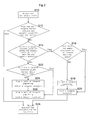
- Fig. 2 is a flowchart showing the details of the control relating to reagent cassette loading into and unloading from the main reagent buffer in the automated analyzer according to the embodiment.
- New analytical items are assigned in step S10. More specifically, analytical items to be executed for given biological samples are requested for each of the biological samples by the operator or from a host to which the automated analyzer is connected. In this step, the analysis using the reagents placed in the subsidiary reagent buffer 12 is requested in addition to the analysis using the reagents placed in the main reagent buffer 4. Detailed information on these newly assigned analytical items is stored into the control unit 200.
- the control unit 200 determines in step S12 whether the reagent cassettes holding the reagents to be used for the requested analytical items are placed in the main reagent buffer 4. If the reagent cassettes are placed, processing skips to step S28, in which the analyses for the new analytical items are then conducted. If the reagent cassettes are not placed, processing advances to step S14.
- the control unit 200 determines in step S14 whether there is a reagent cassette plate not having thereon the reagent to be used for the analysis that follows the ongoing analysis. Assume, for example, that analytical item A is currently being executed and that while reagent "a" for this item is placed on the first plate 13A, reagent "a” is not placed on the second plate 13B. In this example, the second plate 13B is equivalent to the reagent cassette plate not having thereon the reagent to be used for the analysis that follows the ongoing analysis. If the plate is present, processing advances to step S16. If the plate is absent, processing skips to step S22.
- step S16 If a plate not being used for the ongoing analysis is present in the main reagent buffer 4, the control unit 200 stabilize in step S16 whether an empty position exists on that reagent cassette plate (in the above example, the second plate 13B).
- the empty position refers to a location on the plate 13B where a reagent cassette is not placed. If the empty position is present, processing skips to step S20. If the empty position is absent, processing advances to step S18.
- control unit 200 uses the reagent cassette transfer 11 in step S18 to unload a reagent cassette from the subsidiary reagent buffer 12.
- the reagent cassette unloaded here will be selected from the following candidates. In an example, if there is a reagent cassette containing an expired reagent, this cassette will be unloaded. Further, in another example, if the amount of usable reagent left in a reagent cassette is too small for the next analysis, that is, reagent amount level is low, this cassette will be unloaded.
- a reagent for which the analysis is not assigned for more than a definite time i.e., more than a time required for the reagent cassette to be reloaded after being unloaded
- that reagent cassette will be unloaded.
- a reagent cassette containing a reagent infrequently used will be unloaded.
- control unit 200 Upon completion of step S18 or if in step S16 the empty position is determined to be present, the control unit 200 uses the reagent cassette transfer 11 in step S20 to load the unloaded reagent cassette into the main reagent buffer and set the loaded reagent cassette in the empty position. After this, in step S28, the control unit 200 executes the analyses for the new analytical items.
- step S14 if in step S14 a plate not being used for the ongoing analysis is present in the main reagent buffer 4, that is, a plate being used for the ongoing analysis is present, then the control unit 200 stabilize in step S22 whether an empty position exists on that reagent cassette plate (in the foregoing example, the first plate 13A).
- step S24 the control unit 200 brings reagent pipetting to a temporarily stop and after this, uses the reagent cassette transfer 11 to unload a reagent cassette from the subsidiary reagent buffer 12.
- step S26 the control unit 200 uses the reagent cassette transfer 11 to load the unloaded reagent cassette into the main reagent buffer and set the loaded reagent cassette in the empty position.
- step S28 the control unit 200 executes the analyses for the new analytical items.
- this reagent cassette is transferred from the subsidiary reagent buffer 12 to the main reagent buffer 4 by the reagent cassette transfer 11 and then the corresponding analysis is conducted. Execution of this sequence allows not only a reagent cassette in the main reagent buffer, but also a reagent cassette in the subsidiary reagent cassette, to be used for the desired analyses.
- the reagent cassette set in the main reagent buffer 4 is determined to require calibration and/or QC (quality control), these steps are conducted. Further, if the reagent cassette set in the subsidiary reagent buffer 12 is determined to require calibration and/or QC, the calibration follows the transfer of the particular reagent cassette to the main reagent buffer 4. A time required for these steps can be predicted.
- Discontinuation of the analysis due to a lack of the residual amount of reagent can therefore be prevented if the minimum allowable number of untested items is specified so that a sum of the time required for the transfer of the reagent cassette and the time required for the calibration and QC steps is shorter than a time required for the execution of the untested items for the reagent cassette usable for the same analysis as that conducted with the reagent cassette set in the main reagent buffer 4.
- this reagent cassette is transferred to the main reagent buffer in advance and the QC and/or calibration step is conducted.
- reagent cassettes are to be set in the main reagent buffer 4
- a reagent cassette-setting position without a set reagent cassette needs to be created by unloading either reagent cassette before setting a desired reagent cassette.
- the setting of reagent cassettes may conducted after specification of analytical items for the biological sample, so required time for the setting of reagent cassettes should preferably be as short as possible.
- empty reagent cassette-setting positions can be ensured at all times by moving specific reagent cassettes from the main reagent buffer 4 to the subsidiary reagent buffer 12 until the number of empty reagent cassette-setting positions has equaled or exceeded the specified value.
- the specified value here is, for example, from 1 to nearly 4.
- Fig. 3 is a flowchart showing the details of the control relating to creating empty positions on the reagent cassette plates in the automated analyzer according to the present embodiment.
- step S30 the control unit 200 loads reagent cassettes into the main reagent buffer 4.
- step S32 the control unit 200 determines whether at least an X number of empty positions are present on the reagent cassette plates 13A, 13B. If at least the X number of empty positions are present, the control process is completed.
- step S34 determines in step S34 whether the analyses using the reagents present on the reagent cassette plates can be conducted within a fixed time (a time required for the unloading of a reagent cassette).
- step S36 the control unit 200 monitors an elapse of a fixed time (a time required until the analysis using a reagent cassette present on either reagent cassette plate has been completed), and then upon the elapse of the fixed time, executes step S32 once again.
- a fixed time a time required until the analysis using a reagent cassette present on either reagent cassette plate has been completed
- step S34 If in step S34 the analyses are determined not to be conducted within the fixed time, the control unit 200 unloads one reagent cassette in step S38.
- the reagent cassette unloaded here will be, for example, one of two candidates, namely (1) a reagent cassette that cannot be used, even at a new request for the analysis, by reason of expiration of the reagent or an insufficiency in its residual amount, and (2) a reagent cassette infrequently used.
- the reagent cassette taken as example (1) above is transferred from the main reagent cassette 4 to the subsidiary reagent buffer 12. If the reagent cassette taken as example (1) is absent in the main reagent buffer 4, the reagent cassette taken as example (2) above is instead transferred from the main reagent cassette 4 to the subsidiary reagent buffer 12.
- any reagent cassettes containing the reagent for which the analysis is not assigned within a fixed time existing after a need has arisen to unload the reagent cassette may be unloaded either in ascending order of frequency of use within a fixed time existing before the need arises to unload the reagent cassette, or in descending order of length of an elapsed time from immediately previous use of the reagent cassette.
- Such ordering of reagent cassette unloading enables highly efficient use of the reagent cassettes because reagent cassettes which are more frequently used than others can be collected in the main buffer 4.
- the standard that if the analysis is already completed, the reagent cassette is moved to the subsidiary reagent buffer, or if the analysis is not completed, the reagent cassette is moved to the main reagent buffer, can be applied to reagent cassettes for which calibration and/or QC has not been completed, as well as to reagent cassettes for calibration and/or QC has been completed.
- the operator specifies the fixed time in terms of the length of time or the number of tests, a time required for retransfer of the reagent cassette may instead be automatically calculated inside the device.
- a specific reagent cassette for example a cassette containing such a cleaning reagent, pretreatment reagent, or any other reagent that is very low in the frequency of use because the reagent is intended for maintenance only or for analytical items only, may usually be set in the subsidiary reagent buffer and only when a cleaning request or a pretreatment request is issued, may the reagent cassette be transferred to the main reagent buffer. After maintenance or the analysis using the reagent cassette, this cassette may be moved from the main reagent buffer to the subsidiary reagent buffer. Use of this sequence allows a larger number of reagent cassettes to be set in the main reagent buffer and used for analyses.
- reagent cassettes that are larger in an execution count of analytical items may be preferentially stored into the main reagent buffer.
- reagent cassettes of higher priority levels may be stored into the main reagent buffer according to execution priority levels of analysis that have been defined for each analytical item specified by the operator. Use of this sequence allows a larger number of reagent cassettes of the higher priority levels of analysis to be set in the main reagent buffer.
- the priority levels of analysis are stored into a priority assignments table 210 of the control unit 200, shown in Fig. 1 .
- a time required for the setting of reagent cassettes is longer than a time required for the pipetting of reagents
- the reagent-pipetting operation being conducted on the first plate 13A of the main reagent buffer is completed earlier than the reagent cassette-setting operation being conducted on the second plate 13B, then even when next reagent needs to be pipetted into the reagent cassette set on the second plate 13B, the pipetting of the next reagent cannot be started until the currently underway setting of the reagent cassette on the second plate 13B has been completed.
- the analyses may be interrupted during that time.
- An interruption in analyses can be lessened by scheduling the analyses so that the analytical items involving the use of reagent cassettes set on the same plate will be continuously executed.
- Fig. 4 is an explanatory diagram of the analytical reordering method designed to shorten the interruption of analyses in the automated analyzer according to the present embodiment.
- the analyses are scheduled so that as shown in Fig. 4 , order AOr1 that has been input from the host or by the operator will be updated to order AOr2 in which the reagent-pipetting operation using the reagent cassettes set on the first plate 13A and the second plate 13B is repeated a plurality of times in succession.
- order AOr1 that has been input from the host or by the operator will be updated to order AOr2 in which the reagent-pipetting operation using the reagent cassettes set on the first plate 13A and the second plate 13B is repeated a plurality of times in succession.
- the setting of the reagent cassette on the second plate 13B is completed or a gap in time between the completion of the pipetting operation and that of the setting operation is reduced. Consequently, an interruption in the analyses can be prevented from occurring and/or an interruption time can be reduced.
- a time for which the reagent cassettes set on the same plate are continuously used will be longer and an interruption in the analyses will be correspondingly lessened.
- n denotes a ratio of the time required for both kinds of operation and does not need to be an integer
- Fig. 5 is an explanatory diagram showing another example of an analytical reordering method designed to shorten the interruption of analyses in the automated analyzer according to the present embodiment.
- One method of lessening the interruption of analyses is by, as shown in Fig. 5 , setting or unloading a plurality of reagent cassettes 5 at the same time in or from the reagent cassette-setting positions at a reagent cassette loading/unloading port 18B' of the main reagent buffer 4 by means of a reagent cassette transfer 11'.
- frequency at which the plate is to be stopped for reagent cassette setting or unloading can be reduced and an analytical interruption time per unit time can also be reduced.
- the present invention can also be applied to a rectangular plate region that moves rectilinearly.
- the invention can be applied to a structure having a plurality of main reagent buffers and subsidiary reagent buffers, without being limited by the number of main reagent buffers and subsidiary reagent buffers.
- a larger number of reagent cassettes can be used more efficiently by transferring buffer-stored reagent cassettes from the main reagent buffer to the subsidiary reagent buffer, and vice versa.
Landscapes
- Physics & Mathematics (AREA)
- Health & Medical Sciences (AREA)
- Life Sciences & Earth Sciences (AREA)
- Chemical & Material Sciences (AREA)
- Analytical Chemistry (AREA)
- Biochemistry (AREA)
- General Health & Medical Sciences (AREA)
- General Physics & Mathematics (AREA)
- Immunology (AREA)
- Pathology (AREA)
- Automatic Analysis And Handling Materials Therefor (AREA)
Applications Claiming Priority (2)
| Application Number | Priority Date | Filing Date | Title |
|---|---|---|---|
| JP2012011541A JP5898972B2 (ja) | 2012-01-23 | 2012-01-23 | 自動分析装置 |
| PCT/JP2012/083132 WO2013111484A1 (fr) | 2012-01-23 | 2012-12-20 | Dispositif d'analyse automatique |
Publications (3)
| Publication Number | Publication Date |
|---|---|
| EP2808683A1 true EP2808683A1 (fr) | 2014-12-03 |
| EP2808683A4 EP2808683A4 (fr) | 2015-09-23 |
| EP2808683B1 EP2808683B1 (fr) | 2022-02-09 |
Family
ID=48873223
Family Applications (1)
| Application Number | Title | Priority Date | Filing Date |
|---|---|---|---|
| EP12866882.9A Active EP2808683B1 (fr) | 2012-01-23 | 2012-12-20 | Dispositif d'analyse automatique |
Country Status (5)
| Country | Link |
|---|---|
| US (1) | US9846170B2 (fr) |
| EP (1) | EP2808683B1 (fr) |
| JP (1) | JP5898972B2 (fr) |
| CN (1) | CN104067132B (fr) |
| WO (1) | WO2013111484A1 (fr) |
Cited By (3)
| Publication number | Priority date | Publication date | Assignee | Title |
|---|---|---|---|---|
| US10001497B2 (en) | 2013-03-15 | 2018-06-19 | Abbott Laboratories | Diagnostic analyzers with pretreatment carousels and related methods |
| US10197585B2 (en) | 2013-03-15 | 2019-02-05 | Abbott Laboratories | Automated diagnostic analyzers having vertically arranged carousels and related methods |
| US10267818B2 (en) | 2013-03-15 | 2019-04-23 | Abbott Laboratories | Automated diagnostic analyzers having rear accessible track systems and related methods |
Families Citing this family (14)
| Publication number | Priority date | Publication date | Assignee | Title |
|---|---|---|---|---|
| ES2829802T3 (es) * | 2015-01-23 | 2021-06-02 | Hoffmann La Roche | Dispositivo de carga para cargar una plataforma giratoria para reactivos de un instrumento analítico con recipientes de reactivo e instrumento analítico |
| US10908174B2 (en) | 2016-09-16 | 2021-02-02 | Canon Medical Systems Corporation | Automatic analyzing apparatus |
| KR101997340B1 (ko) * | 2017-08-14 | 2019-07-05 | 의료법인녹십자의료재단 | 검체 분류 시스템 |
| JP7019343B2 (ja) * | 2017-08-22 | 2022-02-15 | 東芝テック株式会社 | 薬液滴下装置及びシステム |
| WO2021054456A1 (fr) * | 2019-09-20 | 2021-03-25 | 株式会社日立ハイテク | Dispositif d'analyse automatique |
| JP7292185B2 (ja) * | 2019-11-12 | 2023-06-16 | 株式会社日立ハイテク | 自動分析装置 |
| EP4099019A4 (fr) * | 2020-01-30 | 2024-03-06 | Hitachi High-Tech Corporation | Système d'analyse automatique |
| JP2021135295A (ja) * | 2020-02-21 | 2021-09-13 | キヤノンメディカルシステムズ株式会社 | 自動分析装置 |
| WO2021166512A1 (fr) * | 2020-02-21 | 2021-08-26 | 株式会社日立ハイテク | Dispositif d'analyse automatique |
| JP7327809B2 (ja) * | 2020-03-24 | 2023-08-16 | 株式会社タカゾノ | 薬剤払出装置 |
| CN114088955B (zh) * | 2020-08-24 | 2026-01-09 | 深圳迈瑞生物医疗电子股份有限公司 | 样本分析仪 |
| CN116298345A (zh) * | 2022-12-15 | 2023-06-23 | 中元汇吉生物技术股份有限公司 | 全自动化学发光免疫分析仪及其试剂在线装载/卸载系统和方法 |
| CN116087491A (zh) * | 2022-12-15 | 2023-05-09 | 中元汇吉生物技术股份有限公司 | 全自动化学发光免疫分析仪及其试剂在线更换系统和方法 |
| JPWO2024185403A1 (fr) * | 2023-03-09 | 2024-09-12 |
Family Cites Families (14)
| Publication number | Priority date | Publication date | Assignee | Title |
|---|---|---|---|---|
| JP2000321283A (ja) * | 1999-05-13 | 2000-11-24 | Toshiba Corp | 自動分析装置 |
| JP2004271265A (ja) * | 2003-03-06 | 2004-09-30 | Hitachi High-Technologies Corp | 自動分析装置 |
| JP4033060B2 (ja) * | 2003-07-17 | 2008-01-16 | 株式会社日立ハイテクノロジーズ | 自動分析装置 |
| US7029922B2 (en) * | 2003-07-18 | 2006-04-18 | Dade Behring Inc. | Method for resupplying reagents in an automatic clinical analyzer |
| JP2007303881A (ja) * | 2006-05-09 | 2007-11-22 | Olympus Corp | 試薬容器搬送装置 |
| JP4500822B2 (ja) * | 2007-02-19 | 2010-07-14 | 株式会社日立ハイテクノロジーズ | 自動分析装置 |
| JP4969293B2 (ja) * | 2007-03-30 | 2012-07-04 | シスメックス株式会社 | 検体分析装置 |
| JP4558017B2 (ja) * | 2007-07-31 | 2010-10-06 | 株式会社日立ハイテクノロジーズ | 自動分析装置および自動分析装置の使用方法 |
| JP4866808B2 (ja) * | 2007-07-31 | 2012-02-01 | 株式会社日立ハイテクノロジーズ | 自動分析装置 |
| JP2009068993A (ja) * | 2007-09-13 | 2009-04-02 | Olympus Corp | 分析装置 |
| JP2009068992A (ja) * | 2007-09-13 | 2009-04-02 | Olympus Corp | 分析装置 |
| JP5337600B2 (ja) * | 2009-07-03 | 2013-11-06 | 株式会社日立ハイテクノロジーズ | 自動分析装置及び自動分析装置の制御方法 |
| WO2011012657A1 (fr) * | 2009-07-29 | 2011-02-03 | F. Hoffmann-La Roche Ag | Analyseur automatique |
| JP5517160B2 (ja) * | 2010-06-25 | 2014-06-11 | 株式会社日立ハイテクノロジーズ | 自動分析装置 |
-
2012
- 2012-01-23 JP JP2012011541A patent/JP5898972B2/ja active Active
- 2012-12-20 CN CN201280067745.9A patent/CN104067132B/zh active Active
- 2012-12-20 EP EP12866882.9A patent/EP2808683B1/fr active Active
- 2012-12-20 US US14/373,368 patent/US9846170B2/en active Active
- 2012-12-20 WO PCT/JP2012/083132 patent/WO2013111484A1/fr not_active Ceased
Cited By (9)
| Publication number | Priority date | Publication date | Assignee | Title |
|---|---|---|---|---|
| US10001497B2 (en) | 2013-03-15 | 2018-06-19 | Abbott Laboratories | Diagnostic analyzers with pretreatment carousels and related methods |
| US10197585B2 (en) | 2013-03-15 | 2019-02-05 | Abbott Laboratories | Automated diagnostic analyzers having vertically arranged carousels and related methods |
| US10267818B2 (en) | 2013-03-15 | 2019-04-23 | Abbott Laboratories | Automated diagnostic analyzers having rear accessible track systems and related methods |
| US10775398B2 (en) | 2013-03-15 | 2020-09-15 | Abbott Laboratories | Automated diagnostic analyzers having vertically arranged carousels and related methods |
| US11125766B2 (en) | 2013-03-15 | 2021-09-21 | Abbott Laboratories | Automated diagnostic analyzers having rear accessible track systems and related methods |
| US11435372B2 (en) | 2013-03-15 | 2022-09-06 | Abbott Laboratories | Diagnostic analyzers with pretreatment carousels and related methods |
| US11536739B2 (en) | 2013-03-15 | 2022-12-27 | Abbott Laboratories | Automated diagnostic analyzers having vertically arranged carousels and related methods |
| US12007403B2 (en) | 2013-03-15 | 2024-06-11 | Abbott Laboratories | Automated diagnostic analyzers having rear accessible track systems and related methods |
| US12228583B2 (en) | 2013-03-15 | 2025-02-18 | Abbott Laboratories | Automated diagnostic analyzers having vertically arranged carousels and related methods |
Also Published As
| Publication number | Publication date |
|---|---|
| US20150010436A1 (en) | 2015-01-08 |
| JP5898972B2 (ja) | 2016-04-06 |
| CN104067132B (zh) | 2016-08-24 |
| JP2013148564A (ja) | 2013-08-01 |
| EP2808683B1 (fr) | 2022-02-09 |
| CN104067132A (zh) | 2014-09-24 |
| WO2013111484A1 (fr) | 2013-08-01 |
| US9846170B2 (en) | 2017-12-19 |
| EP2808683A4 (fr) | 2015-09-23 |
Similar Documents
| Publication | Publication Date | Title |
|---|---|---|
| EP2808683B1 (fr) | Dispositif d'analyse automatique | |
| EP1477816B1 (fr) | Analyseur automatique | |
| US9709587B2 (en) | Automatic analyzer and reagent processing method in automatic analyzer | |
| EP2804002B1 (fr) | Système automatisé de laboratoire ayant un module de routage d'échantillons commun | |
| US20180080949A1 (en) | Automated scheduler for laboratory equipment | |
| US11268971B2 (en) | Automated analyzer | |
| CN106053864A (zh) | 试剂管理系统 | |
| WO2018155190A1 (fr) | Analyseur automatisé | |
| JP7053898B2 (ja) | 自動分析システムおよび検体の搬送方法 | |
| US12296330B2 (en) | Pipetting unit and pipetting method for closed liquid containers | |
| CN113272653B (zh) | 自动分析装置、自动分析系统以及检体的自动分析方法 | |
| US12282034B2 (en) | Automatic analysis device | |
| JP5097466B2 (ja) | 自動分析装置 | |
| US20050220671A1 (en) | Controller for automated immunoassay system | |
| US12216134B2 (en) | Automatic analyzer and method thereof | |
| EP4050614A1 (fr) | Procédé et système de gestion de priorités d'échantillons | |
| US20240272189A1 (en) | Consumables container loading/unloading system and method of loading/unloading consumables containers for automated analyzer |
Legal Events
| Date | Code | Title | Description |
|---|---|---|---|
| PUAI | Public reference made under article 153(3) epc to a published international application that has entered the european phase |
Free format text: ORIGINAL CODE: 0009012 |
|
| 17P | Request for examination filed |
Effective date: 20140819 |
|
| AK | Designated contracting states |
Kind code of ref document: A1 Designated state(s): AL AT BE BG CH CY CZ DE DK EE ES FI FR GB GR HR HU IE IS IT LI LT LU LV MC MK MT NL NO PL PT RO RS SE SI SK SM TR |
|
| DAX | Request for extension of the european patent (deleted) | ||
| RA4 | Supplementary search report drawn up and despatched (corrected) |
Effective date: 20150826 |
|
| RIC1 | Information provided on ipc code assigned before grant |
Ipc: G01N 35/00 20060101AFI20150820BHEP Ipc: G01N 35/02 20060101ALI20150820BHEP Ipc: G01N 35/04 20060101ALI20150820BHEP |
|
| STAA | Information on the status of an ep patent application or granted ep patent |
Free format text: STATUS: EXAMINATION IS IN PROGRESS |
|
| 17Q | First examination report despatched |
Effective date: 20180618 |
|
| RAP1 | Party data changed (applicant data changed or rights of an application transferred) |
Owner name: HITACHI HIGH-TECH CORPORATION |
|
| GRAP | Despatch of communication of intention to grant a patent |
Free format text: ORIGINAL CODE: EPIDOSNIGR1 |
|
| STAA | Information on the status of an ep patent application or granted ep patent |
Free format text: STATUS: GRANT OF PATENT IS INTENDED |
|
| INTG | Intention to grant announced |
Effective date: 20210910 |
|
| GRAS | Grant fee paid |
Free format text: ORIGINAL CODE: EPIDOSNIGR3 |
|
| GRAA | (expected) grant |
Free format text: ORIGINAL CODE: 0009210 |
|
| STAA | Information on the status of an ep patent application or granted ep patent |
Free format text: STATUS: THE PATENT HAS BEEN GRANTED |
|
| RIN1 | Information on inventor provided before grant (corrected) |
Inventor name: SUZUKI YOSHIHIRO Inventor name: NAKAMURA KAZUHIRO Inventor name: OKUSA TAKENORI |
|
| AK | Designated contracting states |
Kind code of ref document: B1 Designated state(s): AL AT BE BG CH CY CZ DE DK EE ES FI FR GB GR HR HU IE IS IT LI LT LU LV MC MK MT NL NO PL PT RO RS SE SI SK SM TR |
|
| REG | Reference to a national code |
Ref country code: GB Ref legal event code: FG4D |
|
| REG | Reference to a national code |
Ref country code: CH Ref legal event code: EP Ref country code: AT Ref legal event code: REF Ref document number: 1467827 Country of ref document: AT Kind code of ref document: T Effective date: 20220215 |
|
| REG | Reference to a national code |
Ref country code: DE Ref legal event code: R096 Ref document number: 602012077662 Country of ref document: DE |
|
| REG | Reference to a national code |
Ref country code: IE Ref legal event code: FG4D |
|
| REG | Reference to a national code |
Ref country code: LT Ref legal event code: MG9D |
|
| REG | Reference to a national code |
Ref country code: NL Ref legal event code: MP Effective date: 20220209 |
|
| REG | Reference to a national code |
Ref country code: AT Ref legal event code: MK05 Ref document number: 1467827 Country of ref document: AT Kind code of ref document: T Effective date: 20220209 |
|
| PG25 | Lapsed in a contracting state [announced via postgrant information from national office to epo] |
Ref country code: SE Free format text: LAPSE BECAUSE OF FAILURE TO SUBMIT A TRANSLATION OF THE DESCRIPTION OR TO PAY THE FEE WITHIN THE PRESCRIBED TIME-LIMIT Effective date: 20220209 Ref country code: RS Free format text: LAPSE BECAUSE OF FAILURE TO SUBMIT A TRANSLATION OF THE DESCRIPTION OR TO PAY THE FEE WITHIN THE PRESCRIBED TIME-LIMIT Effective date: 20220209 Ref country code: PT Free format text: LAPSE BECAUSE OF FAILURE TO SUBMIT A TRANSLATION OF THE DESCRIPTION OR TO PAY THE FEE WITHIN THE PRESCRIBED TIME-LIMIT Effective date: 20220609 Ref country code: NO Free format text: LAPSE BECAUSE OF FAILURE TO SUBMIT A TRANSLATION OF THE DESCRIPTION OR TO PAY THE FEE WITHIN THE PRESCRIBED TIME-LIMIT Effective date: 20220509 Ref country code: NL Free format text: LAPSE BECAUSE OF FAILURE TO SUBMIT A TRANSLATION OF THE DESCRIPTION OR TO PAY THE FEE WITHIN THE PRESCRIBED TIME-LIMIT Effective date: 20220209 Ref country code: LT Free format text: LAPSE BECAUSE OF FAILURE TO SUBMIT A TRANSLATION OF THE DESCRIPTION OR TO PAY THE FEE WITHIN THE PRESCRIBED TIME-LIMIT Effective date: 20220209 Ref country code: HR Free format text: LAPSE BECAUSE OF FAILURE TO SUBMIT A TRANSLATION OF THE DESCRIPTION OR TO PAY THE FEE WITHIN THE PRESCRIBED TIME-LIMIT Effective date: 20220209 Ref country code: ES Free format text: LAPSE BECAUSE OF FAILURE TO SUBMIT A TRANSLATION OF THE DESCRIPTION OR TO PAY THE FEE WITHIN THE PRESCRIBED TIME-LIMIT Effective date: 20220209 Ref country code: BG Free format text: LAPSE BECAUSE OF FAILURE TO SUBMIT A TRANSLATION OF THE DESCRIPTION OR TO PAY THE FEE WITHIN THE PRESCRIBED TIME-LIMIT Effective date: 20220509 |
|
| PG25 | Lapsed in a contracting state [announced via postgrant information from national office to epo] |
Ref country code: PL Free format text: LAPSE BECAUSE OF FAILURE TO SUBMIT A TRANSLATION OF THE DESCRIPTION OR TO PAY THE FEE WITHIN THE PRESCRIBED TIME-LIMIT Effective date: 20220209 Ref country code: LV Free format text: LAPSE BECAUSE OF FAILURE TO SUBMIT A TRANSLATION OF THE DESCRIPTION OR TO PAY THE FEE WITHIN THE PRESCRIBED TIME-LIMIT Effective date: 20220209 Ref country code: GR Free format text: LAPSE BECAUSE OF FAILURE TO SUBMIT A TRANSLATION OF THE DESCRIPTION OR TO PAY THE FEE WITHIN THE PRESCRIBED TIME-LIMIT Effective date: 20220510 Ref country code: FI Free format text: LAPSE BECAUSE OF FAILURE TO SUBMIT A TRANSLATION OF THE DESCRIPTION OR TO PAY THE FEE WITHIN THE PRESCRIBED TIME-LIMIT Effective date: 20220209 Ref country code: AT Free format text: LAPSE BECAUSE OF FAILURE TO SUBMIT A TRANSLATION OF THE DESCRIPTION OR TO PAY THE FEE WITHIN THE PRESCRIBED TIME-LIMIT Effective date: 20220209 |
|
| PG25 | Lapsed in a contracting state [announced via postgrant information from national office to epo] |
Ref country code: IS Free format text: LAPSE BECAUSE OF FAILURE TO SUBMIT A TRANSLATION OF THE DESCRIPTION OR TO PAY THE FEE WITHIN THE PRESCRIBED TIME-LIMIT Effective date: 20220609 |
|
| PG25 | Lapsed in a contracting state [announced via postgrant information from national office to epo] |
Ref country code: SM Free format text: LAPSE BECAUSE OF FAILURE TO SUBMIT A TRANSLATION OF THE DESCRIPTION OR TO PAY THE FEE WITHIN THE PRESCRIBED TIME-LIMIT Effective date: 20220209 Ref country code: SK Free format text: LAPSE BECAUSE OF FAILURE TO SUBMIT A TRANSLATION OF THE DESCRIPTION OR TO PAY THE FEE WITHIN THE PRESCRIBED TIME-LIMIT Effective date: 20220209 Ref country code: RO Free format text: LAPSE BECAUSE OF FAILURE TO SUBMIT A TRANSLATION OF THE DESCRIPTION OR TO PAY THE FEE WITHIN THE PRESCRIBED TIME-LIMIT Effective date: 20220209 Ref country code: EE Free format text: LAPSE BECAUSE OF FAILURE TO SUBMIT A TRANSLATION OF THE DESCRIPTION OR TO PAY THE FEE WITHIN THE PRESCRIBED TIME-LIMIT Effective date: 20220209 Ref country code: DK Free format text: LAPSE BECAUSE OF FAILURE TO SUBMIT A TRANSLATION OF THE DESCRIPTION OR TO PAY THE FEE WITHIN THE PRESCRIBED TIME-LIMIT Effective date: 20220209 Ref country code: CZ Free format text: LAPSE BECAUSE OF FAILURE TO SUBMIT A TRANSLATION OF THE DESCRIPTION OR TO PAY THE FEE WITHIN THE PRESCRIBED TIME-LIMIT Effective date: 20220209 |
|
| REG | Reference to a national code |
Ref country code: DE Ref legal event code: R097 Ref document number: 602012077662 Country of ref document: DE |
|
| PG25 | Lapsed in a contracting state [announced via postgrant information from national office to epo] |
Ref country code: AL Free format text: LAPSE BECAUSE OF FAILURE TO SUBMIT A TRANSLATION OF THE DESCRIPTION OR TO PAY THE FEE WITHIN THE PRESCRIBED TIME-LIMIT Effective date: 20220209 |
|
| PLBE | No opposition filed within time limit |
Free format text: ORIGINAL CODE: 0009261 |
|
| STAA | Information on the status of an ep patent application or granted ep patent |
Free format text: STATUS: NO OPPOSITION FILED WITHIN TIME LIMIT |
|
| 26N | No opposition filed |
Effective date: 20221110 |
|
| PG25 | Lapsed in a contracting state [announced via postgrant information from national office to epo] |
Ref country code: SI Free format text: LAPSE BECAUSE OF FAILURE TO SUBMIT A TRANSLATION OF THE DESCRIPTION OR TO PAY THE FEE WITHIN THE PRESCRIBED TIME-LIMIT Effective date: 20220209 |
|
| PG25 | Lapsed in a contracting state [announced via postgrant information from national office to epo] |
Ref country code: IT Free format text: LAPSE BECAUSE OF FAILURE TO SUBMIT A TRANSLATION OF THE DESCRIPTION OR TO PAY THE FEE WITHIN THE PRESCRIBED TIME-LIMIT Effective date: 20220209 |
|
| REG | Reference to a national code |
Ref country code: CH Ref legal event code: PL |
|
| GBPC | Gb: european patent ceased through non-payment of renewal fee |
Effective date: 20221220 |
|
| REG | Reference to a national code |
Ref country code: BE Ref legal event code: MM Effective date: 20221231 |
|
| PG25 | Lapsed in a contracting state [announced via postgrant information from national office to epo] |
Ref country code: LU Free format text: LAPSE BECAUSE OF NON-PAYMENT OF DUE FEES Effective date: 20221220 |
|
| PG25 | Lapsed in a contracting state [announced via postgrant information from national office to epo] |
Ref country code: LI Free format text: LAPSE BECAUSE OF NON-PAYMENT OF DUE FEES Effective date: 20221231 Ref country code: IE Free format text: LAPSE BECAUSE OF NON-PAYMENT OF DUE FEES Effective date: 20221220 Ref country code: GB Free format text: LAPSE BECAUSE OF NON-PAYMENT OF DUE FEES Effective date: 20221220 Ref country code: CH Free format text: LAPSE BECAUSE OF NON-PAYMENT OF DUE FEES Effective date: 20221231 |
|
| PG25 | Lapsed in a contracting state [announced via postgrant information from national office to epo] |
Ref country code: BE Free format text: LAPSE BECAUSE OF NON-PAYMENT OF DUE FEES Effective date: 20221231 |
|
| PG25 | Lapsed in a contracting state [announced via postgrant information from national office to epo] |
Ref country code: HU Free format text: LAPSE BECAUSE OF FAILURE TO SUBMIT A TRANSLATION OF THE DESCRIPTION OR TO PAY THE FEE WITHIN THE PRESCRIBED TIME-LIMIT; INVALID AB INITIO Effective date: 20121220 |
|
| PG25 | Lapsed in a contracting state [announced via postgrant information from national office to epo] |
Ref country code: CY Free format text: LAPSE BECAUSE OF FAILURE TO SUBMIT A TRANSLATION OF THE DESCRIPTION OR TO PAY THE FEE WITHIN THE PRESCRIBED TIME-LIMIT Effective date: 20220209 |
|
| PG25 | Lapsed in a contracting state [announced via postgrant information from national office to epo] |
Ref country code: MK Free format text: LAPSE BECAUSE OF FAILURE TO SUBMIT A TRANSLATION OF THE DESCRIPTION OR TO PAY THE FEE WITHIN THE PRESCRIBED TIME-LIMIT Effective date: 20220209 |
|
| PG25 | Lapsed in a contracting state [announced via postgrant information from national office to epo] |
Ref country code: MC Free format text: LAPSE BECAUSE OF FAILURE TO SUBMIT A TRANSLATION OF THE DESCRIPTION OR TO PAY THE FEE WITHIN THE PRESCRIBED TIME-LIMIT Effective date: 20220209 |
|
| PG25 | Lapsed in a contracting state [announced via postgrant information from national office to epo] |
Ref country code: TR Free format text: LAPSE BECAUSE OF FAILURE TO SUBMIT A TRANSLATION OF THE DESCRIPTION OR TO PAY THE FEE WITHIN THE PRESCRIBED TIME-LIMIT Effective date: 20220209 Ref country code: MC Free format text: LAPSE BECAUSE OF FAILURE TO SUBMIT A TRANSLATION OF THE DESCRIPTION OR TO PAY THE FEE WITHIN THE PRESCRIBED TIME-LIMIT Effective date: 20220209 |
|
| PG25 | Lapsed in a contracting state [announced via postgrant information from national office to epo] |
Ref country code: MT Free format text: LAPSE BECAUSE OF FAILURE TO SUBMIT A TRANSLATION OF THE DESCRIPTION OR TO PAY THE FEE WITHIN THE PRESCRIBED TIME-LIMIT Effective date: 20220209 |
|
| PGFP | Annual fee paid to national office [announced via postgrant information from national office to epo] |
Ref country code: DE Payment date: 20251126 Year of fee payment: 14 |
|
| PGFP | Annual fee paid to national office [announced via postgrant information from national office to epo] |
Ref country code: FR Payment date: 20251119 Year of fee payment: 14 |