EP2808842A2 - Vorrichtung und Verfahren zur Verfolgung und Rekonstruktion dreidimensionaler Objekte - Google Patents
Vorrichtung und Verfahren zur Verfolgung und Rekonstruktion dreidimensionaler Objekte Download PDFInfo
- Publication number
- EP2808842A2 EP2808842A2 EP13190218.1A EP13190218A EP2808842A2 EP 2808842 A2 EP2808842 A2 EP 2808842A2 EP 13190218 A EP13190218 A EP 13190218A EP 2808842 A2 EP2808842 A2 EP 2808842A2
- Authority
- EP
- European Patent Office
- Prior art keywords
- acquisition unit
- image acquisition
- image
- function
- processing unit
- Prior art date
- Legal status (The legal status is an assumption and is not a legal conclusion. Google has not performed a legal analysis and makes no representation as to the accuracy of the status listed.)
- Granted
Links
Images


Classifications
-
- G—PHYSICS
- G06—COMPUTING OR CALCULATING; COUNTING
- G06T—IMAGE DATA PROCESSING OR GENERATION, IN GENERAL
- G06T7/00—Image analysis
- G06T7/50—Depth or shape recovery
- G06T7/55—Depth or shape recovery from multiple images
- G06T7/579—Depth or shape recovery from multiple images from motion
-
- G—PHYSICS
- G06—COMPUTING OR CALCULATING; COUNTING
- G06T—IMAGE DATA PROCESSING OR GENERATION, IN GENERAL
- G06T2207/00—Indexing scheme for image analysis or image enhancement
- G06T2207/10—Image acquisition modality
- G06T2207/10028—Range image; Depth image; 3D point clouds
-
- G—PHYSICS
- G06—COMPUTING OR CALCULATING; COUNTING
- G06T—IMAGE DATA PROCESSING OR GENERATION, IN GENERAL
- G06T2207/00—Indexing scheme for image analysis or image enhancement
- G06T2207/30—Subject of image; Context of image processing
- G06T2207/30244—Camera pose
Definitions
- the present invention relates to an apparatus and method for tracking a three-dimensional object located in space, and for providing a three-dimensional reconstruction of such an object.
- the invention relates to the reconstruction of three-dimensional objects for 3D printing.
- 3D simultaneous localization and mapping is a highly active research area as it is a pre-requisite for many robotic tasks such as localization, navigation, exploration, and path planning. To be truly useful, such systems require the fast and accurate estimation of the robot pose or camera pose as well as the scene geometry.
- the straightforward acquisition of 3D models is also of interest for augmented reality applications including computer games, home decoration, and refurbishment measures. For example, designers and architects can benefit from this technology as it allows them to cost-effectively scan a room or a piece of furniture before starting the actual work.
- Simultaneous localization and mapping refers to both the estimation of the camera pose and the mapping of the environment. This requires a suitable representation of the scene geometry, and the choice of this representation strongly influences the efficiency of pose estimation and map optimization.
- Laser-based localization and mapping approaches often use scan matching or the iterated closest point algorithm (ICP) to estimate the motion between frames.
- Graph SLAM methods use these motion estimates as input to construct and optimize a pose graph, as has been described by R. Riemmerle, G. Grisetti, H. Strasdat, K. Konolige and W. Burgard; "g2o: A general framework for graph optimization "; ICRA, 2011 .
- these methods render a joint map only after pose graph optimization, and this map is generally not used for further pose optimization.
- the resulting maps are often represented as occupancy grid maps or octrees, and are therefore well suited for robot localization or path planning, cf. K.M. Wurm, A. Hornung, M.
- Newcombe S. Izadi, O. Hilliges, D. Molyneaux, D. Kim, A.J. Davison, P. Kohli, J. Shotton, S. Hodges, and A.W. Fitzgibbon; "KinectFusion: Real-time dense surface mapping and tracking"; ISMAR, pages 127-136, 2011 ; recently demonstrated with their famous KinectFusion approach that dense reconstruction is possible in real-time by using a Microsoft Kinect sensor.
- SDF signed distance function
- ICP ICP in a coarse-to-fine manner to estimate the camera motion. For each image, the algorithm first renders a point cloud from the SDF at the previous pose using ray tracing and subsequently aligns this with the next depth image. Point correspondences are found using projective data association and the point-to-plane distance.
- An apparatus for tracking and reconstructing three-dimensional objects comprises a data processing unit, adapted to process image data provided by an image acquisition unit, said image data pertaining to a scene containing a three-dimensional object, wherein said image data comprises image depth data.
- Said data processing unit is adapted to compute a three-dimensional reconstruction of said object from said image data in terms of a function that represents a surface of said object, wherein said data processing unit is adapted to determine a relative position of said image acquisition unit with respect to said object directly from fitting said image depth data provided by said image acquisition unit to said function representing said surface.
- An object in the sense of the present invention, can be any object that can be captured by means of an image acquisition unit, such as a camera.
- Objects in the sense of the present invention hence encompass both living beings, such as humans or animals, or inanimate objects such as furniture or household items.
- the present invention does not require such an additional conversion, and hence is computationally more efficient.
- the accuracy of the reconstruction can be enhanced.
- a direct determining of the relative position of the image acquisition unit with respect to said object can be understood, in the sense of the present invention, not to require an intermediate conversion to point clouds or the use of the iterated closest point algorithm.
- Said position of said image acquisition unit in the sense of the present invention, may comprise a location of the image acquisition unit in space and/or an orientation or pose of the image acquisition unit in space, in particular an orientation or pose with respect to said object.
- said data processing unit is adapted to determine said relative position of said image acquisition unit with respect to said object by maximizing an observation likelihood given in terms of said position of said image acquisition unit and said function representing said surface.
- the observation likelihood may be maximized for said position.
- said function representing said surface is chosen such that said surface of said object corresponds to an equipotential surface of said function.
- the value of the function may be a constant on said surface of said object, but may have other values on points in space not corresponding to said surface.
- said function representing said surface may be a signed distance function.
- said data processing unit may be adapted to iteratively update said function representing said surface based on an observed relative position of said image acquisition unit with respect to said object.
- said data processing unit is adapted to update said function by maximizing an observation likelihood given in terms of a difference between a distance of said image acquisition unit from said surface, said distance being determined from said relative position, and a corresponding distance observed by means of said image acquisition unit. Said observation likelihood can be maximized for said function.
- the inventors have obtained good results with an iterative approach wherein, in a first step, the position of the image acquisition unit is estimated based on said function representing said surface, and wherein, in a subsequent second step, the function representing said surface is updated based on the newly-computed position of the image acquisition unit.
- This sequence may be repeated any number of times, as needed.
- Said difference between the distance of said image acquisition unit from said surface determined from said relative position and the corresponding distance observed by means of said image acquisition unit may be a weighted difference.
- said weights are exponential weights.
- the weights may be chosen such that they have a minimum value larger than zero, irrespective of a value of said difference.
- weight function that does not decrease to zero is particularly suitable for applications in 3D printing, since it ensures that small holes that could stem from occlusions are automatically filled. This allows for the design of "watertight" 3D models. Yet, selecting the minimum value sufficiently small ensures that the values can be quickly overwritten when better observations become available.
- said data processing unit may be adapted to carve an interior of said reconstruction of said object by transforming said function representing said surface.
- volumetric pixels located in an interior portion of said object may be transformed into volumetric pixels located externally of said object, such as by mirroring said volumetric pixels at said surface of said object.
- said data processing unit is adapted to determine a center of mass of said object from said reconstruction.
- Said center of mass may be determined from said function representing said surface.
- Determining the center of mass allows adding a stand to said object, so to ensure that a 3D object may be stably supported after having been printed.
- Said stand may be centered at a position that corresponds to a projection of a center of mass of said object, in particular a vertical projection of a center of mass of said object.
- Said processing unit may be adapted to determine a mesh representing said object, in particular a triangle mesh, wherein said mesh is computed from said function representing said surface.
- Said mesh data may then be sent to a 3D printer for a three-dimensional printing of a representation of said object, or may be used for any other data processing that follows.
- a color value may be assigned to each voxel.
- said apparatus comprises said image acquisition unit, said image acquisition unit being adapted to acquire said image data of said scene containing said three-dimensional object.
- Said image acquisition unit may be a camera, in particular a camera comprising an image depth sensor.
- Said image acquisition unit may provide color data alongside said image depth data.
- Said image acquisition unit may be portable so that it can be moved with respect to said three-dimensional object.
- the image acquisition unit may also be static, and the object may be moved relative to the image acquisition unit.
- the invention also relates to a corresponding method for tracking and reconstructing three-dimensional objects, comprising the steps of: processing image data provided by an image acquisition unit, said image data pertaining to a scene containing a three-dimensional object, wherein said image data comprises image depth data; computing a reconstruction of said object from said image data in terms of a function that represents a surface of said object; and determining a relative position of said image acquisition unit with respect to said object directly from fitting said image depth data provided by said image acquisition unit to said function representing said surface.
- said step of determining said relative position of said image acquisition unit with respect to said object comprises a step of maximizing an observation likelihood given in terms of said position of said image acquisition unit and said function representing said surface.
- Said function representing said surface may be chosen such that said surface of said object corresponds to an equipotential surface of said function.
- said function representing said surface is a signed distance function.
- the method comprises the step of iteratively updating said function representing said surface based on an observed relative position of said image acquisition unit with respect to said object.
- Updating said function may comprise the step of maximizing an observation likelihood given in terms of a difference between a distance of said image acquisition unit from said surface determined from said relative position, and a corresponding distance observed by means of said image acquisition unit. Said observation likelihood may be maximized for said function.
- said difference is a weighted difference.
- Said weights may be exponential weights.
- said weights are chosen such that they have a minimum value larger than zero, irrespectively of a value of said difference.
- the method comprises a step of carving an interior of said reconstruction of said object by transforming said function representing said surface, in particular by transforming volumetric pixels located in an interior portion of said object into volumetric pixels located in an exterior portion of said object.
- the method comprises a step of determining a center of mass of said object from said reconstruction.
- said center of mass may be determined from said function representing said surface.
- the method comprises a step of adding to said reconstruction of said object a stand for said object.
- Said stand may be centered at a position that corresponds to a projection of a center of mass of said object.
- the method comprises a step of determining a mesh representing said object, in particular a triangle mesh.
- Said mesh may be computed from said function representing said surface.
- the method further comprises a step of acquiring said image data from said scene containing said three-dimensional object, in particular by means of an image acquisition unit.
- the invention also relates to a storage medium for storing computer-readable instructions, wherein said computer-readable instructions, when processed in a data processing unit, cause said processing unit to implement a method with some or all of the steps described above.
- updating the signed distance function may involve a comparison of the depth of the voxel cell computed based on the current camera position/pose with the observed depth. The difference between these depths is weighted with an exponential weight function. Based on the updated signed distance function, a meshing and colorization may then be performed in a subsequent step.
- the description also discusses applications of the invention to the scanning and printing of objects using three-dimensional printing technology.
- This second part also describes model-post processing, such as carving to provide a hollow model or addition of a stand for the model.
- the three-dimensional object that shall be tracked and reconstructed such as a person sitting on a chair or a piece of furniture located in a closed room, shall be described in terms of three-dimensional Cartesian coordinates x ⁇ R 3 .
- the object is monitored by means of a camera capable of acquiring a depth image alongside a conventional RGB image.
- An example for such a camera is Microsoft's Kinect Camera.
- the relative movement of the object with respect to the camera will be denoted in terms of a rotation R ⁇ S0 (3) and a translation t ⁇ R 3 .
- the RGB-D camera outputs a three-dimensional color (RGB) image and a depth (D) image, to which we refer by the functions I RGB : R 2 ⁇ R 3 and I d : R 2 ⁇ R .
- the geometry can be represented using a signed distance function (SDF) stored in a voxel grid.
- SDF signed distance function
- the camera rotation R and the translation t according to Equation (1) should be determined to satisfy the criterion that all re-projected points from the depth image lie as close as possible to the zero-crossing in the SDF, corresponding to the surface, i. e., x
- ⁇ x 0 .
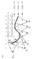
- Fig. 1 This approach for iteratively estimating the camera pose ⁇ such that the SDF values between the re-projected 3D points are minimized is illustrated schematically in Fig. 1 .
- the SDF is constructed from the first n depth images and corresponding camera poses ⁇ 1 , ..., ⁇ n . Based on these values, the current camera pose ⁇ n +1 is determined in an optimization that minimizes the SDF values between the re-projected 3D points.
- the method for camera tracking according to the present invention is a significant improvement over the Kinect fusion algorithm, in which a second depth image is extracted from the SDF that is then aligned to the current depth image using the iterative closest point algorithm (ICP).
- ICP iterative closest point algorithm
- the Kinect fusion approach requires an intermediate data association step between both point clouds, which is computationally involved.
- important information may be lost in the projection of the SDF onto the depth image, which then cannot be used in the iterations of ICP.
- the present invention avoids these disadvantages.
- the Lie algebra is a minimal representation, i. e., it has only six degrees of freedom.
- Equation (15) ⁇ ij ( ⁇ ( k ) ) ⁇ ij ( ⁇ ( k ) ) gives a 6-dimensional vector b ij for each pixel and ⁇ ij ( ⁇ ( k ) ) ⁇ ij ( ⁇ ( k ) ) T gives a 6 ⁇ 6-dimensional matrix A ij for each pixel.
- All gradients can be computed numerically and efficiently in a standard desktop or laptop computer, which allows the method according to the present invention to be implemented with limited resources on standard equipment that is readily available commercially.
- the vectors b ij and matrices A ij are all independent, and may hence be computed in parallel on a graphics processor unit. This allows to implement the invention in real time and yet with high accuracy, which is a significant advantage over many of the prior art techniques.
- the SDF may be represented employing a discrete voxel grid of resolution m , m being a positive integer.
- m being a positive integer.
- the signed distance value ⁇ ( x ) may be determined by tri-linear interpolation between the values of its eight integer neighbors.
- the strategy relies on the computation of the distance of each voxel to the observed surfaces represented by the current depth image.
- Computing the true distance of each voxel is time consuming, since it requires the computation of all shortest paths over the entire volume.
- Even efficient algorithms such as Fast Marching are not well suited for real-time applications.
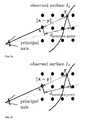
- Fig. 2 Examples for projective distances that will now be described with reference to Fig. 2 are the projective point-to-point distance ( Fig. 2a ) and the projective point-to-plane distance ( Fig. 2b ).
- This distance is signed, i. e., negative values are assigned to voxels in front of the observed surface, and positive values to voxels behind.
- the projective point-to-plane distance is likewise signed, i. e., negative values refer to voxels in front of the surface and positive values to voxels behind.
- the point-to-plane metric has the advantage over the projective point-to-point distance that it is more accurate even when the viewing angle is far from orthogonal to the surface.
- the normal computation may be sensitive to the noise in the depth images, but this can be addressed by employing a bilateral filter with Gaussian kernels.
- Projective distance metrics are only approximations of true distance functions, and hence they can be highly erroneous, especially when the estimated distances are large.
- we truncate the projected distances d and apply a weighting term that blends out large distances.
- d trunc ⁇ - ⁇ if d ⁇ - ⁇ d if d ⁇ ⁇ ⁇ if d > ⁇ for some positive content ⁇ . Due to the truncation according to Equation (30), the gradient of the SDF will be zero in regions that are further away than the pre-determined constant ⁇ from the estimated surface.
- we may employ a weighting function to give higher weights to voxels in front of the observed surface and lower weights to voxels behind.
- Fig. 3b shows a linear weight function in which the weight linearly decreases to zero between given penetration depths ⁇ and ⁇ , for pre-determined constants ⁇ , ⁇ , where ⁇ > ⁇ .
- w lin d ⁇ 1 if d ⁇ ⁇ ⁇ - d ⁇ - ⁇ if d ⁇ ⁇ and d ⁇ ⁇ . 0 if d > ⁇
- the linear model expresses a certain prior for the minimum depth ⁇ of objects in the scene and a linear prior afterwards.
- Fig. 3f and 3e show variations of the constant weight and linear weight functions, respectively.
- Fig. 3d shows a narrow weight with exponential rather than linear slopes on both sides.
- this estimation problem can be formulated as follows.
- ⁇ that maximizes the observation likelihood p d 1 , w 1 , ... , d n , w n
- ⁇ ⁇ ⁇ i 1 n exp 1 2 ⁇ w i ⁇ ⁇ - d i 2
- d i and w i refer to the observed truncated distances and weights in frame i , respectively.
- This computation can be carried out for each voxel. As each voxel does not depend on its neighbors, this update can easily be computed in parallel for all voxels on a standard graphics processor unit. For instance, in an exemplary implementation, the computation time per frame may be approximately 27 ms on a NVIDIA GeForce GTX 560 with 384 cores, and runs easily in real-time with 30 frames per second.
- the signed distance function ⁇ encodes the three-dimensional geometry of the scene. As the surface is located at the zero crossing in the signed distance function, one may apply an implementation of the marching cubes algorithm to extract the corresponding triangle mesh. This approach is described in greater detail by William E. Lorensen, Harvey E. Cline, "Marching Cubes: A High Resolution 3D Surface Construction Algorithm", Computer Graphics 21 (4)163 to 169, 1987 .
- the invention may also involve an estimation of a color texture of the scene.
- the texture may be represented using an additional voxel grid consisting of three channels R , G , B for the color components red, green, blue, respectively and one additional channel for the color weights W c .
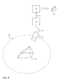
- An exemplary setup is shown schematically in Fig. 4 .
- An object 10 to be scanned and printed such as a small toy pyramid 10 is placed on a stage.
- a camera 12 acquiring depth information alongside color information is moved around the surface of the object 10 along a trajectory 14 to capture an image of the object 10.
- the camera 12 may be Microsoft's Kinect camera.
- the camera 12 generates, at each time step, a color image I RGB and a depth image I d , according to Equation (1).
- the acquired data may be sent via a camera data connection 16 to a data processing unit 18.
- the camera data connection 16 may be a wired connection or a wireless connection.
- the data processing unit 18 may be a laptop or desktop PC comprising a central processor unit (not shown) and a graphics processor unit (not shown).
- the data processing unit 18 is adapted to use the color image I RGB and depth image I d provided by the camera 12 to track the camera position by means of the signed distance function and to reconstruct a triangle mesh of the object 10 in accordance with the method described above in Sections (b) to (g).
- the reconstructed image of the object 10 is converted into printing instructions, which are provided to a 3D printer 20 via a printer data connection 22.
- the printer data connection 22 may again be a wireless connection or a wired connection.
- the printer 20 prints a 3D model 10' of the object 10 in accordance with the printing instructions.
- the present invention allows the fitting of the image depth data provided by the camera 12 to the signed distance function to be performed quickly and with limited computational resources.
- This allows the 3D reconstruction to be performed in real-time on a standard off-the-shelf computer 18.
- the computation runs easily in real-time with 30 frames per second RGB-D data.
- the mesh generation takes around between 1000 and 1500 ms on a single CPU core.
- the resulting triangle mesh typically consists of approximately 200.000 to 500.000 vertices and faces.
- This information may be displayed together with the estimated camera trajectory to a user using Open GL.
- the method according to the present invention allows a live view of a colored 3D model to be shown during scanning on the monitor to provide live feedback to the user. Typically, scanning takes around 10 seconds (300 frames), while the full process typically consumes less than 1 minute on a normal laptop or desktop PC.
- Fig. 4 shows a configuration in which the object 10 to be captured is static, and the camera 12 is moved around the object 10.
- the invention can just as well be practiced in configurations where the camera 12 is static and the object 10 is rotated in front of the camera 12. For instance, a person sitting on a rotating chair may be rotated in front of a static RGB-D camera 12 to acquire a 3D model of the person.
- the method according to the present invention allows detecting when a full 360° turn of the object 10 in front of the camera, or a full 360° turn of the camera 12 around the object 10 is complete.
- the data processing unit 18 may post-process the acquired mesh data to further facilitate 3D printing.
- the triangle mesh acquired with the method according to the present invention may sometimes be unclosed, at positions where objects stick out of the reconstruction volume. This may in particular be the case at the bottom of the object, for which no triangles are generated.
- the model may also be carved automatically prior to printing. This allows reducing the printing costs by a factor of 5 or even more.
- the transformation according to Equation (46) allows voxels that are located deeper than s within the object to be mapped to the outside. Given that the estimate of the signed distance function is only a coarse approximation, the transformation according to Equation (46) may sometimes lead to artifacts and unconnected components.
- This problem can be mitigated by re-computing the signed distance function with the correct signed distance value by finding the nearest neighbor from the pre-computed triangulated mesh.
- To speed up this computation one may insert all vertices into an oct-tree structure and only update voxel cells within the object (i. e., cells with ⁇ > 0).
- FIG. 5 shows some of the steps in the method of three-dimensional surface reconstruction and three-dimensional printing according to an embodiment of the present invention.
- step S10 image depth data I d is acquired, possibly alongside color information I RGB .
- step S 14 after the current camera pose has been estimated, the signed distance function ⁇ is updated.
- the signed distance function encodes the three-dimensional geometry of the scene, and hence may be used for meshing and colorization (step S16), such as by implementing the marching cubes algorithm to extract the corresponding triangle mesh.
- the resulting triangle mesh can then be subjected to post-model processing, such as carving or addition of the stand (step S 18) before being transmitted to the printer for 3D printing (step S20).
Landscapes
- Engineering & Computer Science (AREA)
- Computer Vision & Pattern Recognition (AREA)
- Physics & Mathematics (AREA)
- General Physics & Mathematics (AREA)
- Theoretical Computer Science (AREA)
- Image Analysis (AREA)
- Image Processing (AREA)
- Length Measuring Devices By Optical Means (AREA)
Priority Applications (1)
| Application Number | Priority Date | Filing Date | Title |
|---|---|---|---|
| EP13190218.1A EP2808842B1 (de) | 2013-05-31 | 2013-10-25 | Vorrichtung und Verfahren zur Verfolgung und Rekonstruktion dreidimensionaler Objekte |
Applications Claiming Priority (2)
| Application Number | Priority Date | Filing Date | Title |
|---|---|---|---|
| EP13170117 | 2013-05-31 | ||
| EP13190218.1A EP2808842B1 (de) | 2013-05-31 | 2013-10-25 | Vorrichtung und Verfahren zur Verfolgung und Rekonstruktion dreidimensionaler Objekte |
Publications (3)
| Publication Number | Publication Date |
|---|---|
| EP2808842A2 true EP2808842A2 (de) | 2014-12-03 |
| EP2808842A3 EP2808842A3 (de) | 2014-12-31 |
| EP2808842B1 EP2808842B1 (de) | 2017-08-16 |
Family
ID=48576267
Family Applications (1)
| Application Number | Title | Priority Date | Filing Date |
|---|---|---|---|
| EP13190218.1A Not-in-force EP2808842B1 (de) | 2013-05-31 | 2013-10-25 | Vorrichtung und Verfahren zur Verfolgung und Rekonstruktion dreidimensionaler Objekte |
Country Status (1)
| Country | Link |
|---|---|
| EP (1) | EP2808842B1 (de) |
Cited By (16)
| Publication number | Priority date | Publication date | Assignee | Title |
|---|---|---|---|---|
| JP2017092662A (ja) * | 2015-11-06 | 2017-05-25 | キヤノン株式会社 | 撮像装置及びその制御方法、ならびにプログラム |
| CN110887747A (zh) * | 2019-11-18 | 2020-03-17 | 宁波大学 | 基于三维重构和三维雕刻技术的露天矿山边坡结构面剪切试验的试样制作方法 |
| US20200090407A1 (en) * | 2018-08-13 | 2020-03-19 | Magic Leap, Inc. | Cross reality system |
| EP3652708A1 (de) * | 2017-07-13 | 2020-05-20 | Stratasys Ltd. | Verfahren zum drucken eines 3d-modells aus punktwolkendaten |
| CN111880656A (zh) * | 2020-07-28 | 2020-11-03 | 中国人民解放军国防科技大学 | 一种基于p300信号的智能脑控系统及康复设备 |
| AT16852U1 (de) * | 2016-10-13 | 2020-11-15 | A Tron3D Gmbh | Verfahren zum Erfassen und Optimieren von dreidimensionalen Oberflächengeometrien |
| CN112215750A (zh) * | 2020-09-14 | 2021-01-12 | 湖北工业大学 | 基于rgb-d数据的三维重建方法 |
| CN112287737A (zh) * | 2020-04-10 | 2021-01-29 | 福建电子口岸股份有限公司 | 一种码头港口图像目标检测优化算法 |
| CN113706714A (zh) * | 2021-09-03 | 2021-11-26 | 中科计算技术创新研究院 | 基于深度图像和神经辐射场的新视角合成方法 |
| CN113762068A (zh) * | 2018-05-31 | 2021-12-07 | 谷歌有限责任公司 | 用于估计手的当前姿势的方法和电子装置 |
| CN114140508A (zh) * | 2021-11-26 | 2022-03-04 | 浪潮电子信息产业股份有限公司 | 一种三维重建模型生成的方法、系统、设备及可读存储介质 |
| CN114359032A (zh) * | 2021-12-13 | 2022-04-15 | 华东师范大学 | 一种柱面壁画全景图像生成方法及系统 |
| CN115578450A (zh) * | 2022-09-29 | 2023-01-06 | 北京奇艺世纪科技有限公司 | 一种位置确定方法、装置、电子设备及可读存储介质 |
| US11562542B2 (en) | 2019-12-09 | 2023-01-24 | Magic Leap, Inc. | Cross reality system with simplified programming of virtual content |
| CN117272758A (zh) * | 2023-11-20 | 2023-12-22 | 埃洛克航空科技(北京)有限公司 | 基于三角格网的深度估计方法、装置、计算机设备和介质 |
| CN118334263A (zh) * | 2024-06-11 | 2024-07-12 | 中国科学技术大学 | 基于截断符号距离函数的融合激光点云的高精度建模方法 |
Families Citing this family (12)
| Publication number | Priority date | Publication date | Assignee | Title |
|---|---|---|---|---|
| US11227435B2 (en) | 2018-08-13 | 2022-01-18 | Magic Leap, Inc. | Cross reality system |
| EP3861387B1 (de) | 2018-10-05 | 2025-05-21 | Magic Leap, Inc. | Darstellung eines ortsspezifischen virtuellen inhalts an einem beliebigen ort |
| US11632679B2 (en) | 2019-10-15 | 2023-04-18 | Magic Leap, Inc. | Cross reality system with wireless fingerprints |
| CN114600064B (zh) | 2019-10-15 | 2026-04-24 | 奇跃公司 | 具有定位服务的交叉现实系统 |
| EP4046070A4 (de) | 2019-10-15 | 2023-10-18 | Magic Leap, Inc. | Realitätsübergreifendes system, das mehrere gerätetypen unterstützt |
| JP7604478B2 (ja) | 2019-10-31 | 2024-12-23 | マジック リープ, インコーポレイテッド | 持続座標フレームについての品質情報を伴うクロスリアリティシステム |
| WO2021096931A1 (en) | 2019-11-12 | 2021-05-20 | Magic Leap, Inc. | Cross reality system with localization service and shared location-based content |
| JP7684321B2 (ja) | 2020-02-13 | 2025-05-27 | マジック リープ, インコーポレイテッド | 位置特定に関するジオロケーション情報の優先順位化を伴うクロスリアリティシステム |
| JP7768888B2 (ja) | 2020-02-13 | 2025-11-12 | マジック リープ, インコーポレイテッド | マルチ分解能フレーム記述子を使用したマップ処理を伴うクロスリアリティシステム |
| CN119984235A (zh) | 2020-02-13 | 2025-05-13 | 奇跃公司 | 具有精确共享地图的交叉现实系统 |
| JP7671769B2 (ja) | 2020-02-26 | 2025-05-02 | マジック リープ, インコーポレイテッド | 高速位置特定を伴うクロスリアリティシステム |
| JP2023524446A (ja) | 2020-04-29 | 2023-06-12 | マジック リープ, インコーポレイテッド | 大規模環境のためのクロスリアリティシステム |
Family Cites Families (1)
| Publication number | Priority date | Publication date | Assignee | Title |
|---|---|---|---|---|
| GB201003065D0 (en) * | 2010-02-23 | 2010-04-07 | Simpleware Ltd | Image processing method and method of three-dimensional printing incorporating the same |
-
2013
- 2013-10-25 EP EP13190218.1A patent/EP2808842B1/de not_active Not-in-force
Non-Patent Citations (7)
| Title |
|---|
| F. ENDRES; J. HESS; N. ENGELHARD; J. STURM; D. CREMERS; W. BURGARD: "An evaluation of the RGB-D SLAM systems", ICRA, May 2012 (2012-05-01) |
| J. STURM; N. ENGELHARD; F. ENDRES; W. BURGARD; D. CREMERS: "A benchmarkfor evaluation of RGB-D SLAM systems", IROS, 2012 |
| K.M. WURM; A. HORNUNG; M. BENNEWITZ; C. STACHNISS; W. BURGARD: "OctoMap: A probabilistic, flexible, and compact 3D map representation for robotic systems", WORKSHOP ON BEST PRACTICE IN 3D PERCEPTION AND MODELING FOR MOBILE MANIPULATION AT ICRA, 2010 |
| P. HENRY; M. KRAININ; E. HERBST; X. REN; D. FOX, RGB-D MAPPING: USING DEPTH CAMERAS FOR DENSE 3D MODELING OF INDOOR ENVIRONMENTS, 2010 |
| R. KUMMERLE; G. GRISETTI; H. STRASDAT; K. KONOLIGE; W. BURGARD: "g2o: A general framework for graph optimization", ICRA, 2011 |
| R.A. NEWCOMBE; S. IZADI; O. HILLIGES; D. MOLYNEAUX; D. KIM; A.J. DAVISON; P. KOHLI; J. SHOTTON; S. HODGES; A.W. FITZGIBBON: "KinectFusion: Real-time dense surface mapping and tracking", ISMAR, 2011, pages 127 - 136 |
| WILLIAM E. LORENSEN; HARVEY E. CLINE: "Marching Cubes: A High Resolution 3D Surface Construction Algorithm", COMPUTER GRAPHICS, vol. 21, no. 4, 1987, pages 163 - 169 |
Cited By (23)
| Publication number | Priority date | Publication date | Assignee | Title |
|---|---|---|---|---|
| JP2017092662A (ja) * | 2015-11-06 | 2017-05-25 | キヤノン株式会社 | 撮像装置及びその制御方法、ならびにプログラム |
| AT16852U1 (de) * | 2016-10-13 | 2020-11-15 | A Tron3D Gmbh | Verfahren zum Erfassen und Optimieren von dreidimensionalen Oberflächengeometrien |
| EP3652708B1 (de) * | 2017-07-13 | 2025-08-27 | Stratasys Ltd. | Verfahren zum drucken eines 3d-modells aus punktwolkendaten |
| US11543800B2 (en) * | 2017-07-13 | 2023-01-03 | Stratasys Ltd. | Method of printing a 3D model from point cloud data |
| EP3652708A1 (de) * | 2017-07-13 | 2020-05-20 | Stratasys Ltd. | Verfahren zum drucken eines 3d-modells aus punktwolkendaten |
| CN113762068A (zh) * | 2018-05-31 | 2021-12-07 | 谷歌有限责任公司 | 用于估计手的当前姿势的方法和电子装置 |
| US10957112B2 (en) * | 2018-08-13 | 2021-03-23 | Magic Leap, Inc. | Cross reality system |
| US20200090407A1 (en) * | 2018-08-13 | 2020-03-19 | Magic Leap, Inc. | Cross reality system |
| CN110887747A (zh) * | 2019-11-18 | 2020-03-17 | 宁波大学 | 基于三维重构和三维雕刻技术的露天矿山边坡结构面剪切试验的试样制作方法 |
| US11562542B2 (en) | 2019-12-09 | 2023-01-24 | Magic Leap, Inc. | Cross reality system with simplified programming of virtual content |
| CN112287737A (zh) * | 2020-04-10 | 2021-01-29 | 福建电子口岸股份有限公司 | 一种码头港口图像目标检测优化算法 |
| CN112287737B (zh) * | 2020-04-10 | 2023-06-06 | 福建电子口岸股份有限公司 | 一种码头港口图像目标检测优化算法 |
| CN111880656A (zh) * | 2020-07-28 | 2020-11-03 | 中国人民解放军国防科技大学 | 一种基于p300信号的智能脑控系统及康复设备 |
| CN111880656B (zh) * | 2020-07-28 | 2023-04-07 | 中国人民解放军国防科技大学 | 一种基于p300信号的智能脑控系统及康复设备 |
| CN112215750A (zh) * | 2020-09-14 | 2021-01-12 | 湖北工业大学 | 基于rgb-d数据的三维重建方法 |
| CN113706714A (zh) * | 2021-09-03 | 2021-11-26 | 中科计算技术创新研究院 | 基于深度图像和神经辐射场的新视角合成方法 |
| CN113706714B (zh) * | 2021-09-03 | 2024-01-05 | 中科计算技术创新研究院 | 基于深度图像和神经辐射场的新视角合成方法 |
| CN114140508A (zh) * | 2021-11-26 | 2022-03-04 | 浪潮电子信息产业股份有限公司 | 一种三维重建模型生成的方法、系统、设备及可读存储介质 |
| CN114359032A (zh) * | 2021-12-13 | 2022-04-15 | 华东师范大学 | 一种柱面壁画全景图像生成方法及系统 |
| CN115578450A (zh) * | 2022-09-29 | 2023-01-06 | 北京奇艺世纪科技有限公司 | 一种位置确定方法、装置、电子设备及可读存储介质 |
| CN117272758B (zh) * | 2023-11-20 | 2024-03-15 | 埃洛克航空科技(北京)有限公司 | 基于三角格网的深度估计方法、装置、计算机设备和介质 |
| CN117272758A (zh) * | 2023-11-20 | 2023-12-22 | 埃洛克航空科技(北京)有限公司 | 基于三角格网的深度估计方法、装置、计算机设备和介质 |
| CN118334263A (zh) * | 2024-06-11 | 2024-07-12 | 中国科学技术大学 | 基于截断符号距离函数的融合激光点云的高精度建模方法 |
Also Published As
| Publication number | Publication date |
|---|---|
| EP2808842B1 (de) | 2017-08-16 |
| EP2808842A3 (de) | 2014-12-31 |
Similar Documents
| Publication | Publication Date | Title |
|---|---|---|
| EP2808842B1 (de) | Vorrichtung und Verfahren zur Verfolgung und Rekonstruktion dreidimensionaler Objekte | |
| US11941831B2 (en) | Depth estimation | |
| Bylow et al. | Real-time camera tracking and 3D reconstruction using signed distance functions | |
| Sturm et al. | CopyMe3D: Scanning and printing persons in 3D | |
| Kaess | Simultaneous localization and mapping with infinite planes. | |
| Matthies et al. | Error modeling in stereo navigation | |
| CN108369743B (zh) | 使用多方向相机地图构建空间 | |
| Meister et al. | When can we use kinectfusion for ground truth acquisition | |
| JP5627325B2 (ja) | 位置姿勢計測装置、位置姿勢計測方法、およびプログラム | |
| CN108765548A (zh) | 基于深度相机的三维场景实时重建方法 | |
| Lim et al. | Real-time single camera SLAM using fiducial markers | |
| Hähnel et al. | Probabilistic matching for 3d scan registration | |
| Chen et al. | A novel calibration method between a camera and a 3D LiDAR with infrared images | |
| Schauwecker et al. | Robust and efficient volumetric occupancy mapping with an application to stereo vision | |
| Biswas et al. | Planar polygon extraction and merging from depth images | |
| Pitzer | Automatic reconstruction of textured 3D models | |
| Wan et al. | A study in 3d-reconstruction using kinect sensor | |
| Boittiaux et al. | Homography-based loss function for camera pose regression | |
| Liu et al. | Geometrically stable tracking for depth images based 3D reconstruction on mobile devices | |
| Bunschoten et al. | 3D scene reconstruction from cylindrical panoramic images | |
| Wiemann et al. | An evaluation of open source surface reconstruction software for robotic applications | |
| Yoshisada et al. | Indoor map generation from multiple LiDAR point clouds | |
| Andreasson et al. | Non-iterative vision-based interpolation of 3D laser scans | |
| Buck et al. | Capturing uncertainty in monocular depth estimation: Towards fuzzy voxel maps | |
| CN117333548A (zh) | 一种基于类环面的相机位姿估计方法、系统和存储介质 |
Legal Events
| Date | Code | Title | Description |
|---|---|---|---|
| PUAL | Search report despatched |
Free format text: ORIGINAL CODE: 0009013 |
|
| PUAI | Public reference made under article 153(3) epc to a published international application that has entered the european phase |
Free format text: ORIGINAL CODE: 0009012 |
|
| 17P | Request for examination filed |
Effective date: 20131025 |
|
| AK | Designated contracting states |
Kind code of ref document: A2 Designated state(s): AL AT BE BG CH CY CZ DE DK EE ES FI FR GB GR HR HU IE IS IT LI LT LU LV MC MK MT NL NO PL PT RO RS SE SI SK SM TR |
|
| AX | Request for extension of the european patent |
Extension state: BA ME |
|
| AK | Designated contracting states |
Kind code of ref document: A3 Designated state(s): AL AT BE BG CH CY CZ DE DK EE ES FI FR GB GR HR HU IE IS IT LI LT LU LV MC MK MT NL NO PL PT RO RS SE SI SK SM TR |
|
| AX | Request for extension of the european patent |
Extension state: BA ME |
|
| RIC1 | Information provided on ipc code assigned before grant |
Ipc: G06T 7/00 20060101AFI20141127BHEP |
|
| R17P | Request for examination filed (corrected) |
Effective date: 20150622 |
|
| RBV | Designated contracting states (corrected) |
Designated state(s): AL AT BE BG CH CY CZ DE DK EE ES FI FR GB GR HR HU IE IS IT LI LT LU LV MC MK MT NL NO PL PT RO RS SE SI SK SM TR |
|
| 17Q | First examination report despatched |
Effective date: 20151012 |
|
| REG | Reference to a national code |
Ref country code: DE Ref legal event code: R079 Ref document number: 602013025033 Country of ref document: DE Free format text: PREVIOUS MAIN CLASS: G06T0007000000 Ipc: G06T0007579000 |
|
| GRAP | Despatch of communication of intention to grant a patent |
Free format text: ORIGINAL CODE: EPIDOSNIGR1 |
|
| RIC1 | Information provided on ipc code assigned before grant |
Ipc: G06T 7/579 20170101AFI20170203BHEP |
|
| INTG | Intention to grant announced |
Effective date: 20170307 |
|
| GRAS | Grant fee paid |
Free format text: ORIGINAL CODE: EPIDOSNIGR3 |
|
| GRAA | (expected) grant |
Free format text: ORIGINAL CODE: 0009210 |
|
| AK | Designated contracting states |
Kind code of ref document: B1 Designated state(s): AL AT BE BG CH CY CZ DE DK EE ES FI FR GB GR HR HU IE IS IT LI LT LU LV MC MK MT NL NO PL PT RO RS SE SI SK SM TR |
|
| REG | Reference to a national code |
Ref country code: GB Ref legal event code: FG4D |
|
| REG | Reference to a national code |
Ref country code: CH Ref legal event code: EP |
|
| REG | Reference to a national code |
Ref country code: IE Ref legal event code: FG4D |
|
| REG | Reference to a national code |
Ref country code: AT Ref legal event code: REF Ref document number: 919764 Country of ref document: AT Kind code of ref document: T Effective date: 20170915 |
|
| REG | Reference to a national code |
Ref country code: DE Ref legal event code: R096 Ref document number: 602013025033 Country of ref document: DE |
|
| REG | Reference to a national code |
Ref country code: NL Ref legal event code: MP Effective date: 20170816 |
|
| REG | Reference to a national code |
Ref country code: LT Ref legal event code: MG4D |
|
| REG | Reference to a national code |
Ref country code: AT Ref legal event code: MK05 Ref document number: 919764 Country of ref document: AT Kind code of ref document: T Effective date: 20170816 |
|
| PG25 | Lapsed in a contracting state [announced via postgrant information from national office to epo] |
Ref country code: FI Free format text: LAPSE BECAUSE OF FAILURE TO SUBMIT A TRANSLATION OF THE DESCRIPTION OR TO PAY THE FEE WITHIN THE PRESCRIBED TIME-LIMIT Effective date: 20170816 Ref country code: NO Free format text: LAPSE BECAUSE OF FAILURE TO SUBMIT A TRANSLATION OF THE DESCRIPTION OR TO PAY THE FEE WITHIN THE PRESCRIBED TIME-LIMIT Effective date: 20171116 Ref country code: NL Free format text: LAPSE BECAUSE OF FAILURE TO SUBMIT A TRANSLATION OF THE DESCRIPTION OR TO PAY THE FEE WITHIN THE PRESCRIBED TIME-LIMIT Effective date: 20170816 Ref country code: LT Free format text: LAPSE BECAUSE OF FAILURE TO SUBMIT A TRANSLATION OF THE DESCRIPTION OR TO PAY THE FEE WITHIN THE PRESCRIBED TIME-LIMIT Effective date: 20170816 Ref country code: SE Free format text: LAPSE BECAUSE OF FAILURE TO SUBMIT A TRANSLATION OF THE DESCRIPTION OR TO PAY THE FEE WITHIN THE PRESCRIBED TIME-LIMIT Effective date: 20170816 Ref country code: AT Free format text: LAPSE BECAUSE OF FAILURE TO SUBMIT A TRANSLATION OF THE DESCRIPTION OR TO PAY THE FEE WITHIN THE PRESCRIBED TIME-LIMIT Effective date: 20170816 |
|
| PG25 | Lapsed in a contracting state [announced via postgrant information from national office to epo] |
Ref country code: RS Free format text: LAPSE BECAUSE OF FAILURE TO SUBMIT A TRANSLATION OF THE DESCRIPTION OR TO PAY THE FEE WITHIN THE PRESCRIBED TIME-LIMIT Effective date: 20170816 Ref country code: PL Free format text: LAPSE BECAUSE OF FAILURE TO SUBMIT A TRANSLATION OF THE DESCRIPTION OR TO PAY THE FEE WITHIN THE PRESCRIBED TIME-LIMIT Effective date: 20170816 Ref country code: IS Free format text: LAPSE BECAUSE OF FAILURE TO SUBMIT A TRANSLATION OF THE DESCRIPTION OR TO PAY THE FEE WITHIN THE PRESCRIBED TIME-LIMIT Effective date: 20171216 Ref country code: LV Free format text: LAPSE BECAUSE OF FAILURE TO SUBMIT A TRANSLATION OF THE DESCRIPTION OR TO PAY THE FEE WITHIN THE PRESCRIBED TIME-LIMIT Effective date: 20170816 Ref country code: ES Free format text: LAPSE BECAUSE OF FAILURE TO SUBMIT A TRANSLATION OF THE DESCRIPTION OR TO PAY THE FEE WITHIN THE PRESCRIBED TIME-LIMIT Effective date: 20170816 Ref country code: GR Free format text: LAPSE BECAUSE OF FAILURE TO SUBMIT A TRANSLATION OF THE DESCRIPTION OR TO PAY THE FEE WITHIN THE PRESCRIBED TIME-LIMIT Effective date: 20171117 Ref country code: BG Free format text: LAPSE BECAUSE OF FAILURE TO SUBMIT A TRANSLATION OF THE DESCRIPTION OR TO PAY THE FEE WITHIN THE PRESCRIBED TIME-LIMIT Effective date: 20171116 |
|
| PG25 | Lapsed in a contracting state [announced via postgrant information from national office to epo] |
Ref country code: DK Free format text: LAPSE BECAUSE OF FAILURE TO SUBMIT A TRANSLATION OF THE DESCRIPTION OR TO PAY THE FEE WITHIN THE PRESCRIBED TIME-LIMIT Effective date: 20170816 Ref country code: RO Free format text: LAPSE BECAUSE OF FAILURE TO SUBMIT A TRANSLATION OF THE DESCRIPTION OR TO PAY THE FEE WITHIN THE PRESCRIBED TIME-LIMIT Effective date: 20170816 Ref country code: CZ Free format text: LAPSE BECAUSE OF FAILURE TO SUBMIT A TRANSLATION OF THE DESCRIPTION OR TO PAY THE FEE WITHIN THE PRESCRIBED TIME-LIMIT Effective date: 20170816 |
|
| REG | Reference to a national code |
Ref country code: DE Ref legal event code: R119 Ref document number: 602013025033 Country of ref document: DE |
|
| PG25 | Lapsed in a contracting state [announced via postgrant information from national office to epo] |
Ref country code: SK Free format text: LAPSE BECAUSE OF FAILURE TO SUBMIT A TRANSLATION OF THE DESCRIPTION OR TO PAY THE FEE WITHIN THE PRESCRIBED TIME-LIMIT Effective date: 20170816 Ref country code: EE Free format text: LAPSE BECAUSE OF FAILURE TO SUBMIT A TRANSLATION OF THE DESCRIPTION OR TO PAY THE FEE WITHIN THE PRESCRIBED TIME-LIMIT Effective date: 20170816 Ref country code: IT Free format text: LAPSE BECAUSE OF FAILURE TO SUBMIT A TRANSLATION OF THE DESCRIPTION OR TO PAY THE FEE WITHIN THE PRESCRIBED TIME-LIMIT Effective date: 20170816 Ref country code: SM Free format text: LAPSE BECAUSE OF FAILURE TO SUBMIT A TRANSLATION OF THE DESCRIPTION OR TO PAY THE FEE WITHIN THE PRESCRIBED TIME-LIMIT Effective date: 20170816 Ref country code: MC Free format text: LAPSE BECAUSE OF FAILURE TO SUBMIT A TRANSLATION OF THE DESCRIPTION OR TO PAY THE FEE WITHIN THE PRESCRIBED TIME-LIMIT Effective date: 20170816 |
|
| REG | Reference to a national code |
Ref country code: CH Ref legal event code: PL |
|
| PLBE | No opposition filed within time limit |
Free format text: ORIGINAL CODE: 0009261 |
|
| STAA | Information on the status of an ep patent application or granted ep patent |
Free format text: STATUS: NO OPPOSITION FILED WITHIN TIME LIMIT |
|
| 26N | No opposition filed |
Effective date: 20180517 |
|
| GBPC | Gb: european patent ceased through non-payment of renewal fee |
Effective date: 20171116 |
|
| REG | Reference to a national code |
Ref country code: IE Ref legal event code: MM4A |
|
| REG | Reference to a national code |
Ref country code: FR Ref legal event code: ST Effective date: 20180629 |
|
| PG25 | Lapsed in a contracting state [announced via postgrant information from national office to epo] |
Ref country code: DE Free format text: LAPSE BECAUSE OF NON-PAYMENT OF DUE FEES Effective date: 20180501 Ref country code: CH Free format text: LAPSE BECAUSE OF NON-PAYMENT OF DUE FEES Effective date: 20171031 Ref country code: LI Free format text: LAPSE BECAUSE OF NON-PAYMENT OF DUE FEES Effective date: 20171031 Ref country code: LU Free format text: LAPSE BECAUSE OF NON-PAYMENT OF DUE FEES Effective date: 20171025 |
|
| REG | Reference to a national code |
Ref country code: BE Ref legal event code: MM Effective date: 20171031 |
|
| PG25 | Lapsed in a contracting state [announced via postgrant information from national office to epo] |
Ref country code: FR Free format text: LAPSE BECAUSE OF NON-PAYMENT OF DUE FEES Effective date: 20171031 Ref country code: BE Free format text: LAPSE BECAUSE OF NON-PAYMENT OF DUE FEES Effective date: 20171031 Ref country code: SI Free format text: LAPSE BECAUSE OF FAILURE TO SUBMIT A TRANSLATION OF THE DESCRIPTION OR TO PAY THE FEE WITHIN THE PRESCRIBED TIME-LIMIT Effective date: 20170816 |
|
| PG25 | Lapsed in a contracting state [announced via postgrant information from national office to epo] |
Ref country code: MT Free format text: LAPSE BECAUSE OF NON-PAYMENT OF DUE FEES Effective date: 20171025 |
|
| PG25 | Lapsed in a contracting state [announced via postgrant information from national office to epo] |
Ref country code: IE Free format text: LAPSE BECAUSE OF NON-PAYMENT OF DUE FEES Effective date: 20171025 |
|
| PG25 | Lapsed in a contracting state [announced via postgrant information from national office to epo] |
Ref country code: GB Free format text: LAPSE BECAUSE OF NON-PAYMENT OF DUE FEES Effective date: 20171116 |
|
| PG25 | Lapsed in a contracting state [announced via postgrant information from national office to epo] |
Ref country code: HU Free format text: LAPSE BECAUSE OF FAILURE TO SUBMIT A TRANSLATION OF THE DESCRIPTION OR TO PAY THE FEE WITHIN THE PRESCRIBED TIME-LIMIT; INVALID AB INITIO Effective date: 20131025 |
|
| PG25 | Lapsed in a contracting state [announced via postgrant information from national office to epo] |
Ref country code: CY Free format text: LAPSE BECAUSE OF FAILURE TO SUBMIT A TRANSLATION OF THE DESCRIPTION OR TO PAY THE FEE WITHIN THE PRESCRIBED TIME-LIMIT Effective date: 20170816 |
|
| PG25 | Lapsed in a contracting state [announced via postgrant information from national office to epo] |
Ref country code: MK Free format text: LAPSE BECAUSE OF FAILURE TO SUBMIT A TRANSLATION OF THE DESCRIPTION OR TO PAY THE FEE WITHIN THE PRESCRIBED TIME-LIMIT Effective date: 20170816 |
|
| PG25 | Lapsed in a contracting state [announced via postgrant information from national office to epo] |
Ref country code: TR Free format text: LAPSE BECAUSE OF FAILURE TO SUBMIT A TRANSLATION OF THE DESCRIPTION OR TO PAY THE FEE WITHIN THE PRESCRIBED TIME-LIMIT Effective date: 20170816 |
|
| PG25 | Lapsed in a contracting state [announced via postgrant information from national office to epo] |
Ref country code: PT Free format text: LAPSE BECAUSE OF FAILURE TO SUBMIT A TRANSLATION OF THE DESCRIPTION OR TO PAY THE FEE WITHIN THE PRESCRIBED TIME-LIMIT Effective date: 20170816 |
|
| PG25 | Lapsed in a contracting state [announced via postgrant information from national office to epo] |
Ref country code: HR Free format text: LAPSE BECAUSE OF FAILURE TO SUBMIT A TRANSLATION OF THE DESCRIPTION OR TO PAY THE FEE WITHIN THE PRESCRIBED TIME-LIMIT Effective date: 20170816 |
|
| PG25 | Lapsed in a contracting state [announced via postgrant information from national office to epo] |
Ref country code: AL Free format text: LAPSE BECAUSE OF FAILURE TO SUBMIT A TRANSLATION OF THE DESCRIPTION OR TO PAY THE FEE WITHIN THE PRESCRIBED TIME-LIMIT Effective date: 20170816 |