EP2808921A1 - Batteriemodul - Google Patents
Batteriemodul Download PDFInfo
- Publication number
- EP2808921A1 EP2808921A1 EP14170305.8A EP14170305A EP2808921A1 EP 2808921 A1 EP2808921 A1 EP 2808921A1 EP 14170305 A EP14170305 A EP 14170305A EP 2808921 A1 EP2808921 A1 EP 2808921A1
- Authority
- EP
- European Patent Office
- Prior art keywords
- battery cells
- battery module
- cover
- battery
- wall
- Prior art date
- Legal status (The legal status is an assumption and is not a legal conclusion. Google has not performed a legal analysis and makes no representation as to the accuracy of the status listed.)
- Granted
Links
Images


Classifications
-
- H—ELECTRICITY
- H01—ELECTRIC ELEMENTS
- H01M—PROCESSES OR MEANS, e.g. BATTERIES, FOR THE DIRECT CONVERSION OF CHEMICAL ENERGY INTO ELECTRICAL ENERGY
- H01M50/00—Constructional details or processes of manufacture of the non-active parts of electrochemical cells other than fuel cells, e.g. hybrid cells
- H01M50/20—Mountings; Secondary casings or frames; Racks, modules or packs; Suspension devices; Shock absorbers; Transport or carrying devices; Holders
- H01M50/262—Mountings; Secondary casings or frames; Racks, modules or packs; Suspension devices; Shock absorbers; Transport or carrying devices; Holders with fastening means, e.g. locks
-
- H—ELECTRICITY
- H01—ELECTRIC ELEMENTS
- H01M—PROCESSES OR MEANS, e.g. BATTERIES, FOR THE DIRECT CONVERSION OF CHEMICAL ENERGY INTO ELECTRICAL ENERGY
- H01M10/00—Secondary cells; Manufacture thereof
- H01M10/04—Construction or manufacture in general
- H01M10/0436—Small-sized flat cells or batteries for portable equipment
-
- H—ELECTRICITY
- H01—ELECTRIC ELEMENTS
- H01M—PROCESSES OR MEANS, e.g. BATTERIES, FOR THE DIRECT CONVERSION OF CHEMICAL ENERGY INTO ELECTRICAL ENERGY
- H01M50/00—Constructional details or processes of manufacture of the non-active parts of electrochemical cells other than fuel cells, e.g. hybrid cells
- H01M50/20—Mountings; Secondary casings or frames; Racks, modules or packs; Suspension devices; Shock absorbers; Transport or carrying devices; Holders
- H01M50/204—Racks, modules or packs for multiple batteries or multiple cells
- H01M50/207—Racks, modules or packs for multiple batteries or multiple cells characterised by their shape
- H01M50/209—Racks, modules or packs for multiple batteries or multiple cells characterised by their shape adapted for prismatic or rectangular cells
-
- H—ELECTRICITY
- H01—ELECTRIC ELEMENTS
- H01M—PROCESSES OR MEANS, e.g. BATTERIES, FOR THE DIRECT CONVERSION OF CHEMICAL ENERGY INTO ELECTRICAL ENERGY
- H01M50/00—Constructional details or processes of manufacture of the non-active parts of electrochemical cells other than fuel cells, e.g. hybrid cells
- H01M50/20—Mountings; Secondary casings or frames; Racks, modules or packs; Suspension devices; Shock absorbers; Transport or carrying devices; Holders
- H01M50/271—Lids or covers for the racks or secondary casings
-
- H—ELECTRICITY
- H01—ELECTRIC ELEMENTS
- H01M—PROCESSES OR MEANS, e.g. BATTERIES, FOR THE DIRECT CONVERSION OF CHEMICAL ENERGY INTO ELECTRICAL ENERGY
- H01M50/00—Constructional details or processes of manufacture of the non-active parts of electrochemical cells other than fuel cells, e.g. hybrid cells
- H01M50/20—Mountings; Secondary casings or frames; Racks, modules or packs; Suspension devices; Shock absorbers; Transport or carrying devices; Holders
- H01M50/289—Mountings; Secondary casings or frames; Racks, modules or packs; Suspension devices; Shock absorbers; Transport or carrying devices; Holders characterised by spacing elements or positioning means within frames, racks or packs
-
- H—ELECTRICITY
- H01—ELECTRIC ELEMENTS
- H01M—PROCESSES OR MEANS, e.g. BATTERIES, FOR THE DIRECT CONVERSION OF CHEMICAL ENERGY INTO ELECTRICAL ENERGY
- H01M50/00—Constructional details or processes of manufacture of the non-active parts of electrochemical cells other than fuel cells, e.g. hybrid cells
- H01M50/50—Current conducting connections for cells or batteries
- H01M50/502—Interconnectors for connecting terminals of adjacent batteries; Interconnectors for connecting cells outside a battery casing
-
- H—ELECTRICITY
- H01—ELECTRIC ELEMENTS
- H01M—PROCESSES OR MEANS, e.g. BATTERIES, FOR THE DIRECT CONVERSION OF CHEMICAL ENERGY INTO ELECTRICAL ENERGY
- H01M2220/00—Batteries for particular applications
- H01M2220/20—Batteries in motive systems, e.g. vehicle, ship, plane
-
- Y—GENERAL TAGGING OF NEW TECHNOLOGICAL DEVELOPMENTS; GENERAL TAGGING OF CROSS-SECTIONAL TECHNOLOGIES SPANNING OVER SEVERAL SECTIONS OF THE IPC; TECHNICAL SUBJECTS COVERED BY FORMER USPC CROSS-REFERENCE ART COLLECTIONS [XRACs] AND DIGESTS
- Y02—TECHNOLOGIES OR APPLICATIONS FOR MITIGATION OR ADAPTATION AGAINST CLIMATE CHANGE
- Y02E—REDUCTION OF GREENHOUSE GAS [GHG] EMISSIONS, RELATED TO ENERGY GENERATION, TRANSMISSION OR DISTRIBUTION
- Y02E60/00—Enabling technologies; Technologies with a potential or indirect contribution to GHG emissions mitigation
- Y02E60/10—Energy storage using batteries
-
- Y—GENERAL TAGGING OF NEW TECHNOLOGICAL DEVELOPMENTS; GENERAL TAGGING OF CROSS-SECTIONAL TECHNOLOGIES SPANNING OVER SEVERAL SECTIONS OF THE IPC; TECHNICAL SUBJECTS COVERED BY FORMER USPC CROSS-REFERENCE ART COLLECTIONS [XRACs] AND DIGESTS
- Y02—TECHNOLOGIES OR APPLICATIONS FOR MITIGATION OR ADAPTATION AGAINST CLIMATE CHANGE
- Y02P—CLIMATE CHANGE MITIGATION TECHNOLOGIES IN THE PRODUCTION OR PROCESSING OF GOODS
- Y02P70/00—Climate change mitigation technologies in the production process for final industrial or consumer products
- Y02P70/50—Manufacturing or production processes characterised by the final manufactured product
Definitions
- the present invention relates to a battery module.
- a high-power battery module using a non-aqueous electrolyte with high energy density has recently been developed.
- the high-power battery module is configured as a large-capacity battery module manufactured by connecting a plurality of battery cells in series to be used, for example, in driving motors of devices requiring high power, e.g., electric vehicles, hybrid vehicles, and the like.
- a battery pack can be configured by electrically connecting a plurality of such battery modules to one another.
- a battery module includes a novel member, and has improved safety and process efficiency due to the novel member.
- battery cells are firmly fixed without being moved by an external force.
- a battery module includes: a plurality of aligned battery cells each including a terminal, and a casing for housing the battery cells.
- the casing comprises a pair of end plates each configured to face a wide surface of a battery cell at a respective outer end of the plurality of battery cells; side plates configured to support side surfaces of the battery cells at respective sides of the plurality of battery cells; a cover configured to cover the battery cells, and at least one of the side plates comprises a wall portion, an extension portion offset from the wall portion and a seating portion arranged to receive an end portion of the cover.
- At least one of an upper portion or a lower portion of the side plate may include the seating portion and the extension portion, and the cover may have an accommodating portion into which the extension portion is inserted.
- the side plate may include the wall portion opposite to the side surfaces of the battery cells, the seating portion surrounding at least a portion of the battery cells, and the extension portion extending away from the battery cells.
- the seating portion may be perpendicular to the wall portion, and the extension portion may extend from a surface of the seating portion to be perpendicular to the surface of the seating portion.
- the seating portion may be perpendicular to the wall portion, and the extension portion may extend from an end of the seating portion to be perpendicular to the seating portion.
- the side plate may further include a flange portion at an end portion of the wall portion and configured to surround at least a portion of an end plate of the pair of end plates.
- the flange portion may be bent at the wall portion to be perpendicular to the wall portion.
- the cover may be mounted on the battery cells, and may include a first partition wall and a second partition wall inwardly spaced apart from the first partition wall.
- the extension portion may be inserted between the first and second partition walls.
- a length of the first partition wall may be less than that of the second partition wall on respective surfaces of the first and second partition walls that are opposite to each other.
- a length of the first partition wall may be equal to that of the second partition wall on respective surfaces of the first and second partition walls that are opposite to each other.
- the battery module may further include a barrier between neighbouring battery cells of the plurality of battery cells and spacing the neighbouring battery cells apart from each other, and the side plates may include one or more openings positioned corresponding to the barrier.
- the side plates may include a first fastening portion
- the cover may include a second fastening portion at a position corresponding to the first fastening portion and being fastened to the first fastening portion.
- the first fastening portion may be extended in parallel to the wall portion at the end portion of the wall portion, and covers an outer surface of the cover.
- the first fastening portion may be adjacent to the end plate, and the seating portion may be spaced apart from the first fastening portion.
- the extension portion may be extended at the seating portion to be parallel to the first fastening portion.
- the cover may cover the first surfaces of the battery cells, and may have at least one first hole portion through which a terminal passes.
- a battery module has improved process efficiency due to a novel member.
- a battery module includes battery cells that are firmly fixed without being moved by an external force.
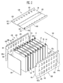
- a battery module 100 includes a plurality of battery cells 10 each having terminals 11 and 12 on a first surface 14 thereof, the plurality of battery cells 10 being aligned or arranged in a direction; a casing for housing the battery cells including a pair of end plates 110 configured to face wide surfaces of the battery cells 10 at the outside of the plurality of battery cells 10; side plates 120 configured to support side surfaces of the battery cells 10 at opposite sides of the plurality of battery cells 10; and a cover 130 configured to cover any one of the first surfaces 14 and second surfaces opposite to the first surfaces 14 of the battery cells 10. Any one of upper and lower portions of the side plate 120 is bent to overlap with an end portion 132a of the cover 130.
- the cover 130 in one embodiment, may be provided to press the seating portion of the side plate 120.
- a seating portion 122 and an extension portion 123 are provided at any one of the upper and lower portions of the side plate 120.
- the seating portion 122 is overlapped with the end portion 132a of the cover 130, and the extension portion 123 is protruded at the seating portion 122 to face the cover 130.
- the cover 130 in one embodiment, has an accommodating portion 131 into which the extension portion 123 is inserted.
- the battery cell 10 in one embodiment, includes a battery case having the first surface 14, and an electrode assembly and an electrolyte, which are accommodated in the battery case.
- the electrode assembly and the electrolyte generate energy through an electrochemical reaction therebetween.
- the first surface 14 of the battery cell 10 may include a cap assembly.
- the terminals 11 and 12 may be provided on the first surface 14.
- the terminals 11 and 12 may include positive and negative electrode terminals 11 and 12 having different polarities.
- a vent portion 13 may be provided in the first surface 14 and may act as a passage through which gas generated inside the battery cell 10 is exhausted to the outside of the battery cell 10.
- Neighbouring battery cells 10, in one embodiment are electrically connected to each other through a bus bar 15, and the bus bar 15 may be fixed by a nut 16 or the like.
- the battery module 100 may further include a barrier 50 interposed between neighbouring battery cells 10 such that the battery cells 10 are spaced apart from each other.
- One or more openings 125 may be provided in the side plate 120 at a position corresponding to the barrier 50.
- a cooling medium may be flowed in the battery module 100 through the openings 125 of the side plate 120.
- the cooling medium is flowed in a space formed by the barrier 50, so as to perform a heat exchange with the battery cell 10.
- the battery module 100 includes the pair of end plates 110 opposite to each other, the side plates 120 connecting the pair of end plates 110 to each other, and the cover 130 covering one or more of the first surface 14 and the second surface opposite the first surface 14 of the battery cells 10.
- the battery cells 10 are aligned in a direction such that wide surfaces of the battery cells 10 are opposite to each other, and the end plates 110 may be provided to face wide surfaces of outermost battery cells 10 of the plurality of battery cells 10.
- the side plates 120 are connected to the pair of end plates 110 so as to support side surfaces of the battery cells 10.
- the cover 130 is provided on only the first surfaces 14 of the battery cells 10, the present invention is not limited thereto. In another embodiment, the cover 130 may be provided to cover one or more of the first surface 14 of the battery cell 10 and the second surface opposite to the first surface 14, i.e. the bottom surface of the battery cell 10.
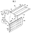
- FIG. 3 is a perspective view of a side plate and a cover of the battery module 100, according to an embodiment of the present invention.
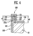
- FIG. 4 is a partial sectional view of the battery module 100, taken along the line A-A of FIG. 1 .
- the side plate 120 may include a wall portion 121 opposite to a side surface of the battery cell 10, a seating portion 122 bent at an end portion 121a of at least one of upper and lower portions of the wall portion 121 to surround at least one portion of the battery cell 10, and an extension portion 123 extended at the seating portion 122 to face a direction opposite to that of the battery cell 10.
- the seating portion 122 may be bent perpendicular to the wall portion 121 at the end portion 121a of the wall portion 121, and the extension portion 123 may be extended perpendicular to the seating portion 122 at an end of the seating portion 122. That is, the seating portion 122 may be parallel or approximately parallel to the first surface 14 of the battery cell 10, such that one end of the seating portion 122 is connected to the wall portion 121 and the other end of the seating portion 122 is connected to the extension portion 123.
- the side plate 120 may further include a flange portion 124 at one or both of left and right end portions 121b of the wall portion 121 to surround at least one portion of one or both of the end plates 110.
- the flange portion 124 may be bent perpendicular to the wall portion 121.
- the end plate 110 may be firmly fixed by the side plate 120 without any separate fastening member.
- the cover 130 in one embodiment, has a mounting surface 134 mounted on the battery cells 10, and one or more first hole portions 135 and one or more second hole portions 136 may be provided in the mounting surface 134.
- the terminals 11 and 12 of the battery cell 10 may pass through the first hole portions 135, and the second hole portion 136 allows the vent portions 13 of the battery cells 10 to be exposed therethrough.
- the end portion 132a of the cover 130 may come in contact with the seating portion 122 of the side plate 120.
- First and second partition walls 132 and 133 protruding towards the battery cell 10 may be respectively provided at both sides of the cover 130.
- the first partition wall 132 may be provided adjacent to the end portion 121a of the wall portion 121 of the side plate 120, and the second partition wall 133 may be provided to be inwardly spaced apart from the first partition wall 132.
- the second partition wall 133 is connected to the mounting surface 134 of the cover 130.
- the extension portion 123 of the side plate 120 may be inserted between the first and second partition walls 132 and 133.
- the extension portion 123 may be forcibly inserted into the accommodating portion 131 provided between the first and second partition walls 132 and 133.
- a length a1 of the first partition wall 132 may be shorter than a length a2 of the second partition wall 133 on respective surfaces where the first and second partition walls 132 and 133 are opposite to each other.
- the seating portion 122 and the extension portion 123 of the side plate 120 are fastened to the cover 130, and the flange portion 124 of the side plate 120 is fixed to the end plate 110.
- the side plate 120, the end plate 110, and the cover 130 are connected to one another, and accordingly, the plurality of battery cells 10 may be firmly fixed without any separate fastening member.
- FIGS. 5 to 8 Various other embodiments of the present invention are described below with reference to FIGS. 5 to 8 . Components and aspects of these embodiments, except for the differences described below, may be the same or similar to those of the battery module 100 described above with reference to FIGS. 1 to 4 , and, therefore, further detailed description of the same or similar components and aspects will be omitted.
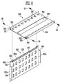
- FIG. 5 is a perspective view of a side plate and a cover of a battery module according to another embodiment of the present invention.
- FIG. 6 is a sectional view showing a state in which the side plate and the cover of FIG. 5 are coupled to each other.
- an extension portion 223 of a side plate 220 is inserted into an accommodating portion 231 of a cover 230.
- the cover 230 may press at least one portion of a seating portion 222 of the side plate 220.
- a wall portion 221 of the side plate 220 is provided to support side surfaces of the battery cells 10 of the battery module.
- the seating portion 222 is connected to at least one end portion 221a of upper and lower end portions of the wall portion 221, and a flange portion 224 is provided at one or both of left and right end portions 221b of the wall portion 221.
- One or more openings 225 may be provided in the wall portion 221.
- the cover 230 may have a mounting surface 234 mounted above first surfaces of the battery cells 10 or below second surfaces of the battery cells 10 opposite the first surfaces.
- one or more first hole portions 235 corresponding to terminals of the battery cells 10 and one or more second hole portions 236 corresponding to vent portions of the battery cells 10 may be provided in the mounting surface 234.
- the seating portion 222 of the side plate 220 may be bent at the wall portion 221 to be perpendicular to the wall portion 221, and the extension portion 223 of the side plate 220 may be extended on a surface of the seating portion 222 to be perpendicular to the surface of the seating portion 222.
- the extension portion 223 is extended approximately from the middle of the surface of the seating portion 222, and the seating portion 222 includes one side 222a connected to the wall portion 221 and another side 222b including an end of the seating portion 222, with the extension portion 223 extending from a location therebetween.
- the cover 230 may include a first partition wall 232 having an end 232a contacted with the one side 222a of the seating portion 222 and a second partition wall 233 contacted with the another side 222b of the seating portion 222.
- the first partition wall 232 may be parallel or approximately parallel to the wall portion 221 of the side plate 220, and the second partition wall 233 may be connected to the mounting surface 234 of the cover 230.
- the accommodating portion 231 may be provided between the first and second partition walls 232 and 233, and the extension portion 223 may be fastened to the accommodating portion 231 by being inserted into the accommodating portion 231.
- a length b1 of the first partition wall 232 corresponds to (e.g., is equal to) a length b2 of the second partition wall 233 on surfaces where the first and second partition walls 232 and 233 are opposite to each other.
- FIG. 7 is a perspective view of a battery module according to another embodiment of the present invention.
- FIG. 8 is a perspective view of a side plate and a cover of the battery module of FIG. 7 .
- a first fastening portion 326 may be provided in a side plate 320, and a second fastening portion 337 at a location corresponding to the first fastening portion 326 may be provided in a cover 330 to fasten the cover 330 to the side plate 320.
- the first and second fastening portions 326 and 337 may be fastened by a separate fastening member 20.
- the fastening member 20 may include a bolt or stud.
- the side plate 320 may include a wall portion 321, a seating portion 322 bent at an end portion 321a of at least one of upper and lower portions of the wall portion 321, and an extension portion 323 bent toward the cover 330 at the seating portion 322.
- a flange portion 324 may be provided at one or both of left and right end portions 321b of the wall portion 321, and one or more openings 325 may be provided in the wall portion 321 so as to correspond to the barrier 50 provided between the battery cells 10.
- the cover 330 is mounted on the first surface of the battery cell 10.
- the cover 330 may include a mounting surface 334 having one or more first hole portions 335 and one or more second hole portions 336.
- the terminals 11 and 12 may be protruded through the first hole portions 335, and the second hole portion 336 allows the vent portion 13 to be exposed therethrough.
- the first fastening portion 326 in one embodiment, may be extended in parallel to the wall portion 321 at any one of upper and lower portions of the wall portion 321 of the side plate 320, so as to cover an outer surface of the cover 330.
- the first fastening portion 326 may be provided near or adjacent to an end plate 310, and the seating portion 322 is connected to the wall portion 321.
- the seating portion 322 has a width narrower than that of the wall portion 321, and is spaced apart from the first fastening portion 326.
- the extension portion 323 may be extended at the seating portion 322 to be parallel to the first fastening portion 326.
- An accommodating portion 331 into which the extension portion 323 of the side plate 320 is inserted may be provided in a space between a second partition wall 333 connected to the mounting surface 334 of the cover 330 and a first partition wall 332 outwardly spaced apart from the second partition wall 333.
- the extension portion 323 is inserted into the accommodating portion 331, and the first fastening portion 326 of the side plate 320 may be overlapped with an outer surface of the first partition wall 332 of the cover 330 and then fastened to the second fastening portion 337 by the separate fastening member 20. Accordingly, fastening between the side plate 320 and the cover 330 may be increased, such that the plurality of battery cells 10 may be firmly fixed.
Landscapes
- Chemical & Material Sciences (AREA)
- Chemical Kinetics & Catalysis (AREA)
- Electrochemistry (AREA)
- General Chemical & Material Sciences (AREA)
- Engineering & Computer Science (AREA)
- Manufacturing & Machinery (AREA)
- Battery Mounting, Suspending (AREA)
Applications Claiming Priority (1)
| Application Number | Priority Date | Filing Date | Title |
|---|---|---|---|
| KR1020130061182A KR101749191B1 (ko) | 2013-05-29 | 2013-05-29 | 배터리 모듈 |
Publications (2)
| Publication Number | Publication Date |
|---|---|
| EP2808921A1 true EP2808921A1 (de) | 2014-12-03 |
| EP2808921B1 EP2808921B1 (de) | 2019-09-11 |
Family
ID=50819639
Family Applications (1)
| Application Number | Title | Priority Date | Filing Date |
|---|---|---|---|
| EP14170305.8A Active EP2808921B1 (de) | 2013-05-29 | 2014-05-28 | Batteriemodul |
Country Status (4)
| Country | Link |
|---|---|
| US (1) | US9570721B2 (de) |
| EP (1) | EP2808921B1 (de) |
| KR (1) | KR101749191B1 (de) |
| CN (1) | CN104218197B (de) |
Cited By (3)
| Publication number | Priority date | Publication date | Assignee | Title |
|---|---|---|---|---|
| CN106941142A (zh) * | 2016-01-05 | 2017-07-11 | Lg电子株式会社 | 电池模块、制造电池模块的方法及使用电池模块的电动车 |
| EP3792992A4 (de) * | 2018-11-12 | 2021-08-18 | Lg Chem, Ltd. | Batteriemodul mit modulgehäuse |
| WO2022263677A1 (de) * | 2021-06-18 | 2022-12-22 | Webasto SE | Batteriemodul und antriebsbatterie |
Families Citing this family (18)
| Publication number | Priority date | Publication date | Assignee | Title |
|---|---|---|---|---|
| KR102453383B1 (ko) * | 2015-10-19 | 2022-10-07 | 삼성에스디아이 주식회사 | 이차 전지 모듈 |
| JP6629140B2 (ja) * | 2016-05-31 | 2020-01-15 | 日立オートモティブシステムズ株式会社 | 蓄電モジュール |
| US10873111B2 (en) | 2016-08-09 | 2020-12-22 | Wisk Aero Llc | Battery with compression and prevention of thermal runaway propagation features |
| CN106058112B (zh) * | 2016-08-12 | 2023-12-01 | 东莞力朗电池科技有限公司 | 一种圆柱型电池模组 |
| KR102067714B1 (ko) * | 2016-11-17 | 2020-01-17 | 주식회사 엘지화학 | 배터리 모듈 및 이를 포함하는 배터리 팩 |
| CN108878699B (zh) * | 2017-05-15 | 2021-03-09 | 宁德时代新能源科技股份有限公司 | 电池模组 |
| CN106935758A (zh) * | 2017-05-16 | 2017-07-07 | 惠州亿纬锂能股份有限公司 | 高性能热管理动力电池模组及电池组 |
| JP7108909B2 (ja) * | 2017-09-26 | 2022-07-29 | パナソニックIpマネジメント株式会社 | 拘束部材および電池モジュール |
| KR102497037B1 (ko) * | 2017-12-06 | 2023-02-08 | 현대자동차주식회사 | 차량용 배터리팩 구조 |
| KR102241965B1 (ko) | 2017-12-26 | 2021-04-16 | 주식회사 엘지화학 | 전지 팩 및 이의 제조 방법 |
| US10756398B2 (en) | 2018-06-22 | 2020-08-25 | Wisk Aero Llc | Capacitance reducing battery submodule with thermal runaway propagation prevention and containment features |
| US10593920B2 (en) | 2018-08-13 | 2020-03-17 | Wisk Aero Llc | Capacitance reduction in battery systems |
| DE202018106448U1 (de) * | 2018-11-14 | 2019-01-16 | Webasto SE | Deckel für ein Batteriemodul, Batteriemodulanordnung und Batterie |
| KR102392767B1 (ko) | 2018-12-26 | 2022-04-28 | 주식회사 엘지에너지솔루션 | 내측 커버를 포함하는 배터리 모듈 |
| KR102873754B1 (ko) | 2020-04-01 | 2025-10-17 | 삼성에스디아이 주식회사 | 배터리 팩 |
| PL4131618T3 (pl) * | 2020-07-02 | 2025-09-01 | Lg Energy Solution, Ltd. | Moduł akumulatorowy z kieszenią zdolną do wychwytywania płomieni i iskier wyrzucanych w czasie pęcznienia |
| KR102875637B1 (ko) * | 2020-11-27 | 2025-10-22 | 주식회사 엘지에너지솔루션 | 배터리 모듈, 배터리 팩, 및 전력 저장 장치 |
| WO2023013466A1 (ja) * | 2021-08-02 | 2023-02-09 | 株式会社Gsユアサ | 蓄電装置 |
Citations (3)
| Publication number | Priority date | Publication date | Assignee | Title |
|---|---|---|---|---|
| GB187287A (en) * | 1921-07-06 | 1922-10-06 | Ingo Emmanuell Kohlmeyer | Improvements in outside containers or boxes of electrical storage batteries or accumulators |
| US20120164504A1 (en) * | 2010-12-27 | 2012-06-28 | Tomokazu Takashina | Power source apparatus, dust-free case, and vehicle equipped with the power source apparatus |
| DE102011003535A1 (de) * | 2011-02-02 | 2012-08-02 | Behr Gmbh & Co. Kg | Verspannungsvorrichtungen |
Family Cites Families (11)
| Publication number | Priority date | Publication date | Assignee | Title |
|---|---|---|---|---|
| JP3932934B2 (ja) * | 2002-03-05 | 2007-06-20 | ソニー株式会社 | 二次電池収納ケース |
| JP4757508B2 (ja) * | 2005-03-01 | 2011-08-24 | 日本電気株式会社 | 電気デバイス集合体 |
| JP5070697B2 (ja) * | 2005-12-19 | 2012-11-14 | 日産自動車株式会社 | 電池モジュール |
| JP4974578B2 (ja) * | 2006-04-27 | 2012-07-11 | 三洋電機株式会社 | パック電池 |
| JP2008277085A (ja) | 2007-04-27 | 2008-11-13 | Sanyo Electric Co Ltd | パック電池 |
| JP5142605B2 (ja) | 2007-06-28 | 2013-02-13 | 三洋電機株式会社 | 車両用の電源装置 |
| US9224999B2 (en) * | 2008-10-30 | 2015-12-29 | Infineon Technologies Americas Corp. | Vehicle battery module |
| KR101058102B1 (ko) * | 2009-12-18 | 2011-08-24 | 에스비리모티브 주식회사 | 배터리 팩 |
| US9065111B2 (en) | 2010-05-26 | 2015-06-23 | Samsung Sdi Co., Ltd. | Battery pack |
| JP5605252B2 (ja) * | 2011-02-08 | 2014-10-15 | トヨタ自動車株式会社 | 蓄電装置 |
| KR101271883B1 (ko) | 2011-07-22 | 2013-06-05 | 로베르트 보쉬 게엠베하 | 배터리 모듈 |
-
2013
- 2013-05-29 KR KR1020130061182A patent/KR101749191B1/ko active Active
-
2014
- 2014-03-04 US US14/197,105 patent/US9570721B2/en active Active
- 2014-04-08 CN CN201410138625.4A patent/CN104218197B/zh active Active
- 2014-05-28 EP EP14170305.8A patent/EP2808921B1/de active Active
Patent Citations (3)
| Publication number | Priority date | Publication date | Assignee | Title |
|---|---|---|---|---|
| GB187287A (en) * | 1921-07-06 | 1922-10-06 | Ingo Emmanuell Kohlmeyer | Improvements in outside containers or boxes of electrical storage batteries or accumulators |
| US20120164504A1 (en) * | 2010-12-27 | 2012-06-28 | Tomokazu Takashina | Power source apparatus, dust-free case, and vehicle equipped with the power source apparatus |
| DE102011003535A1 (de) * | 2011-02-02 | 2012-08-02 | Behr Gmbh & Co. Kg | Verspannungsvorrichtungen |
Cited By (6)
| Publication number | Priority date | Publication date | Assignee | Title |
|---|---|---|---|---|
| CN106941142A (zh) * | 2016-01-05 | 2017-07-11 | Lg电子株式会社 | 电池模块、制造电池模块的方法及使用电池模块的电动车 |
| CN106941142B (zh) * | 2016-01-05 | 2019-09-10 | Lg电子株式会社 | 电池模块、制造电池模块的方法及使用电池模块的电动车 |
| EP3792992A4 (de) * | 2018-11-12 | 2021-08-18 | Lg Chem, Ltd. | Batteriemodul mit modulgehäuse |
| JP2021523517A (ja) * | 2018-11-12 | 2021-09-02 | エルジー・ケム・リミテッド | モジュールハウジングを含むバッテリーモジュール |
| US11984612B2 (en) | 2018-11-12 | 2024-05-14 | Lg Energy Solution, Ltd. | Battery module comprising module housing |
| WO2022263677A1 (de) * | 2021-06-18 | 2022-12-22 | Webasto SE | Batteriemodul und antriebsbatterie |
Also Published As
| Publication number | Publication date |
|---|---|
| EP2808921B1 (de) | 2019-09-11 |
| US9570721B2 (en) | 2017-02-14 |
| KR20140140380A (ko) | 2014-12-09 |
| KR101749191B1 (ko) | 2017-06-20 |
| CN104218197A (zh) | 2014-12-17 |
| CN104218197B (zh) | 2018-08-03 |
| US20140356690A1 (en) | 2014-12-04 |
Similar Documents
| Publication | Publication Date | Title |
|---|---|---|
| EP2808921B1 (de) | Batteriemodul | |
| US9166260B2 (en) | Battery module | |
| JP6088185B2 (ja) | バッテリモジュール | |
| US9337458B2 (en) | Battery module | |
| JP6148202B2 (ja) | 蓄電装置の冷却構造 | |
| KR101252952B1 (ko) | 배터리 셀의 유동을 방지하는 배터리 모듈 | |
| KR101287107B1 (ko) | 연결부재를 가지는 전지 모듈 | |
| KR102394688B1 (ko) | 배터리 모듈 | |
| EP2808922A1 (de) | Batteriemodul | |
| US20120040226A1 (en) | Battery Module | |
| US9012063B2 (en) | Battery module | |
| US20140220396A1 (en) | Battery pack | |
| EP2521203B1 (de) | Batteriemodul | |
| KR101199217B1 (ko) | 배터리 모듈 | |
| WO2012101728A1 (ja) | 電池モジュール及びそれに用いる組電池 | |
| KR20130023562A (ko) | 배터리 셀 및 이를 이용한 배터리 모듈 | |
| KR101750487B1 (ko) | 외부 입출력 단자 및 버스 바의 장착 수단을 포함하는 전지모듈 | |
| EP2797138A1 (de) | Batteriepack | |
| US20150171482A1 (en) | Battery module | |
| US20190280353A1 (en) | Cell Pack | |
| EP3496179B1 (de) | Verbinder für ein batteriepack | |
| KR20140052442A (ko) | 배터리 팩 |
Legal Events
| Date | Code | Title | Description |
|---|---|---|---|
| PUAI | Public reference made under article 153(3) epc to a published international application that has entered the european phase |
Free format text: ORIGINAL CODE: 0009012 |
|
| 17P | Request for examination filed |
Effective date: 20140528 |
|
| AK | Designated contracting states |
Kind code of ref document: A1 Designated state(s): AL AT BE BG CH CY CZ DE DK EE ES FI FR GB GR HR HU IE IS IT LI LT LU LV MC MK MT NL NO PL PT RO RS SE SI SK SM TR |
|
| AX | Request for extension of the european patent |
Extension state: BA ME |
|
| R17P | Request for examination filed (corrected) |
Effective date: 20150603 |
|
| RBV | Designated contracting states (corrected) |
Designated state(s): AL AT BE BG CH CY CZ DE DK EE ES FI FR GB GR HR HU IE IS IT LI LT LU LV MC MK MT NL NO PL PT RO RS SE SI SK SM TR |
|
| 17Q | First examination report despatched |
Effective date: 20160630 |
|
| STAA | Information on the status of an ep patent application or granted ep patent |
Free format text: STATUS: EXAMINATION IS IN PROGRESS |
|
| GRAP | Despatch of communication of intention to grant a patent |
Free format text: ORIGINAL CODE: EPIDOSNIGR1 |
|
| STAA | Information on the status of an ep patent application or granted ep patent |
Free format text: STATUS: GRANT OF PATENT IS INTENDED |
|
| INTG | Intention to grant announced |
Effective date: 20190430 |
|
| GRAS | Grant fee paid |
Free format text: ORIGINAL CODE: EPIDOSNIGR3 |
|
| GRAA | (expected) grant |
Free format text: ORIGINAL CODE: 0009210 |
|
| STAA | Information on the status of an ep patent application or granted ep patent |
Free format text: STATUS: THE PATENT HAS BEEN GRANTED |
|
| AK | Designated contracting states |
Kind code of ref document: B1 Designated state(s): AL AT BE BG CH CY CZ DE DK EE ES FI FR GB GR HR HU IE IS IT LI LT LU LV MC MK MT NL NO PL PT RO RS SE SI SK SM TR |
|
| REG | Reference to a national code |
Ref country code: GB Ref legal event code: FG4D |
|
| REG | Reference to a national code |
Ref country code: CH Ref legal event code: EP |
|
| REG | Reference to a national code |
Ref country code: AT Ref legal event code: REF Ref document number: 1179630 Country of ref document: AT Kind code of ref document: T Effective date: 20190915 |
|
| REG | Reference to a national code |
Ref country code: DE Ref legal event code: R096 Ref document number: 602014053307 Country of ref document: DE Ref country code: IE Ref legal event code: FG4D |
|
| REG | Reference to a national code |
Ref country code: NL Ref legal event code: MP Effective date: 20190911 |
|
| REG | Reference to a national code |
Ref country code: LT Ref legal event code: MG4D |
|
| PG25 | Lapsed in a contracting state [announced via postgrant information from national office to epo] |
Ref country code: HR Free format text: LAPSE BECAUSE OF FAILURE TO SUBMIT A TRANSLATION OF THE DESCRIPTION OR TO PAY THE FEE WITHIN THE PRESCRIBED TIME-LIMIT Effective date: 20190911 Ref country code: LT Free format text: LAPSE BECAUSE OF FAILURE TO SUBMIT A TRANSLATION OF THE DESCRIPTION OR TO PAY THE FEE WITHIN THE PRESCRIBED TIME-LIMIT Effective date: 20190911 Ref country code: NO Free format text: LAPSE BECAUSE OF FAILURE TO SUBMIT A TRANSLATION OF THE DESCRIPTION OR TO PAY THE FEE WITHIN THE PRESCRIBED TIME-LIMIT Effective date: 20191211 Ref country code: BG Free format text: LAPSE BECAUSE OF FAILURE TO SUBMIT A TRANSLATION OF THE DESCRIPTION OR TO PAY THE FEE WITHIN THE PRESCRIBED TIME-LIMIT Effective date: 20191211 Ref country code: FI Free format text: LAPSE BECAUSE OF FAILURE TO SUBMIT A TRANSLATION OF THE DESCRIPTION OR TO PAY THE FEE WITHIN THE PRESCRIBED TIME-LIMIT Effective date: 20190911 Ref country code: SE Free format text: LAPSE BECAUSE OF FAILURE TO SUBMIT A TRANSLATION OF THE DESCRIPTION OR TO PAY THE FEE WITHIN THE PRESCRIBED TIME-LIMIT Effective date: 20190911 |
|
| PG25 | Lapsed in a contracting state [announced via postgrant information from national office to epo] |
Ref country code: RS Free format text: LAPSE BECAUSE OF FAILURE TO SUBMIT A TRANSLATION OF THE DESCRIPTION OR TO PAY THE FEE WITHIN THE PRESCRIBED TIME-LIMIT Effective date: 20190911 Ref country code: LV Free format text: LAPSE BECAUSE OF FAILURE TO SUBMIT A TRANSLATION OF THE DESCRIPTION OR TO PAY THE FEE WITHIN THE PRESCRIBED TIME-LIMIT Effective date: 20190911 Ref country code: GR Free format text: LAPSE BECAUSE OF FAILURE TO SUBMIT A TRANSLATION OF THE DESCRIPTION OR TO PAY THE FEE WITHIN THE PRESCRIBED TIME-LIMIT Effective date: 20191212 Ref country code: AL Free format text: LAPSE BECAUSE OF FAILURE TO SUBMIT A TRANSLATION OF THE DESCRIPTION OR TO PAY THE FEE WITHIN THE PRESCRIBED TIME-LIMIT Effective date: 20190911 Ref country code: ES Free format text: LAPSE BECAUSE OF FAILURE TO SUBMIT A TRANSLATION OF THE DESCRIPTION OR TO PAY THE FEE WITHIN THE PRESCRIBED TIME-LIMIT Effective date: 20190911 |
|
| REG | Reference to a national code |
Ref country code: AT Ref legal event code: MK05 Ref document number: 1179630 Country of ref document: AT Kind code of ref document: T Effective date: 20190911 |
|
| PG25 | Lapsed in a contracting state [announced via postgrant information from national office to epo] |
Ref country code: PL Free format text: LAPSE BECAUSE OF FAILURE TO SUBMIT A TRANSLATION OF THE DESCRIPTION OR TO PAY THE FEE WITHIN THE PRESCRIBED TIME-LIMIT Effective date: 20190911 Ref country code: EE Free format text: LAPSE BECAUSE OF FAILURE TO SUBMIT A TRANSLATION OF THE DESCRIPTION OR TO PAY THE FEE WITHIN THE PRESCRIBED TIME-LIMIT Effective date: 20190911 Ref country code: AT Free format text: LAPSE BECAUSE OF FAILURE TO SUBMIT A TRANSLATION OF THE DESCRIPTION OR TO PAY THE FEE WITHIN THE PRESCRIBED TIME-LIMIT Effective date: 20190911 Ref country code: RO Free format text: LAPSE BECAUSE OF FAILURE TO SUBMIT A TRANSLATION OF THE DESCRIPTION OR TO PAY THE FEE WITHIN THE PRESCRIBED TIME-LIMIT Effective date: 20190911 Ref country code: IT Free format text: LAPSE BECAUSE OF FAILURE TO SUBMIT A TRANSLATION OF THE DESCRIPTION OR TO PAY THE FEE WITHIN THE PRESCRIBED TIME-LIMIT Effective date: 20190911 Ref country code: PT Free format text: LAPSE BECAUSE OF FAILURE TO SUBMIT A TRANSLATION OF THE DESCRIPTION OR TO PAY THE FEE WITHIN THE PRESCRIBED TIME-LIMIT Effective date: 20200113 Ref country code: NL Free format text: LAPSE BECAUSE OF FAILURE TO SUBMIT A TRANSLATION OF THE DESCRIPTION OR TO PAY THE FEE WITHIN THE PRESCRIBED TIME-LIMIT Effective date: 20190911 |
|
| PG25 | Lapsed in a contracting state [announced via postgrant information from national office to epo] |
Ref country code: CZ Free format text: LAPSE BECAUSE OF FAILURE TO SUBMIT A TRANSLATION OF THE DESCRIPTION OR TO PAY THE FEE WITHIN THE PRESCRIBED TIME-LIMIT Effective date: 20190911 Ref country code: IS Free format text: LAPSE BECAUSE OF FAILURE TO SUBMIT A TRANSLATION OF THE DESCRIPTION OR TO PAY THE FEE WITHIN THE PRESCRIBED TIME-LIMIT Effective date: 20200224 Ref country code: SK Free format text: LAPSE BECAUSE OF FAILURE TO SUBMIT A TRANSLATION OF THE DESCRIPTION OR TO PAY THE FEE WITHIN THE PRESCRIBED TIME-LIMIT Effective date: 20190911 Ref country code: SM Free format text: LAPSE BECAUSE OF FAILURE TO SUBMIT A TRANSLATION OF THE DESCRIPTION OR TO PAY THE FEE WITHIN THE PRESCRIBED TIME-LIMIT Effective date: 20190911 |
|
| REG | Reference to a national code |
Ref country code: DE Ref legal event code: R097 Ref document number: 602014053307 Country of ref document: DE |
|
| PLBE | No opposition filed within time limit |
Free format text: ORIGINAL CODE: 0009261 |
|
| STAA | Information on the status of an ep patent application or granted ep patent |
Free format text: STATUS: NO OPPOSITION FILED WITHIN TIME LIMIT |
|
| PG2D | Information on lapse in contracting state deleted |
Ref country code: IS |
|
| PG25 | Lapsed in a contracting state [announced via postgrant information from national office to epo] |
Ref country code: DK Free format text: LAPSE BECAUSE OF FAILURE TO SUBMIT A TRANSLATION OF THE DESCRIPTION OR TO PAY THE FEE WITHIN THE PRESCRIBED TIME-LIMIT Effective date: 20190911 Ref country code: IS Free format text: LAPSE BECAUSE OF FAILURE TO SUBMIT A TRANSLATION OF THE DESCRIPTION OR TO PAY THE FEE WITHIN THE PRESCRIBED TIME-LIMIT Effective date: 20200112 |
|
| 26N | No opposition filed |
Effective date: 20200615 |
|
| PG25 | Lapsed in a contracting state [announced via postgrant information from national office to epo] |
Ref country code: SI Free format text: LAPSE BECAUSE OF FAILURE TO SUBMIT A TRANSLATION OF THE DESCRIPTION OR TO PAY THE FEE WITHIN THE PRESCRIBED TIME-LIMIT Effective date: 20190911 |
|
| REG | Reference to a national code |
Ref country code: DE Ref legal event code: R079 Ref document number: 602014053307 Country of ref document: DE Free format text: PREVIOUS MAIN CLASS: H01M0002100000 Ipc: H01M0050200000 |
|
| PG25 | Lapsed in a contracting state [announced via postgrant information from national office to epo] |
Ref country code: MC Free format text: LAPSE BECAUSE OF FAILURE TO SUBMIT A TRANSLATION OF THE DESCRIPTION OR TO PAY THE FEE WITHIN THE PRESCRIBED TIME-LIMIT Effective date: 20190911 Ref country code: CH Free format text: LAPSE BECAUSE OF NON-PAYMENT OF DUE FEES Effective date: 20200531 Ref country code: LI Free format text: LAPSE BECAUSE OF NON-PAYMENT OF DUE FEES Effective date: 20200531 |
|
| REG | Reference to a national code |
Ref country code: BE Ref legal event code: MM Effective date: 20200531 |
|
| PG25 | Lapsed in a contracting state [announced via postgrant information from national office to epo] |
Ref country code: LU Free format text: LAPSE BECAUSE OF NON-PAYMENT OF DUE FEES Effective date: 20200528 |
|
| PG25 | Lapsed in a contracting state [announced via postgrant information from national office to epo] |
Ref country code: IE Free format text: LAPSE BECAUSE OF NON-PAYMENT OF DUE FEES Effective date: 20200528 |
|
| PG25 | Lapsed in a contracting state [announced via postgrant information from national office to epo] |
Ref country code: BE Free format text: LAPSE BECAUSE OF NON-PAYMENT OF DUE FEES Effective date: 20200531 |
|
| PG25 | Lapsed in a contracting state [announced via postgrant information from national office to epo] |
Ref country code: TR Free format text: LAPSE BECAUSE OF FAILURE TO SUBMIT A TRANSLATION OF THE DESCRIPTION OR TO PAY THE FEE WITHIN THE PRESCRIBED TIME-LIMIT Effective date: 20190911 Ref country code: MT Free format text: LAPSE BECAUSE OF FAILURE TO SUBMIT A TRANSLATION OF THE DESCRIPTION OR TO PAY THE FEE WITHIN THE PRESCRIBED TIME-LIMIT Effective date: 20190911 Ref country code: CY Free format text: LAPSE BECAUSE OF FAILURE TO SUBMIT A TRANSLATION OF THE DESCRIPTION OR TO PAY THE FEE WITHIN THE PRESCRIBED TIME-LIMIT Effective date: 20190911 |
|
| PG25 | Lapsed in a contracting state [announced via postgrant information from national office to epo] |
Ref country code: MK Free format text: LAPSE BECAUSE OF FAILURE TO SUBMIT A TRANSLATION OF THE DESCRIPTION OR TO PAY THE FEE WITHIN THE PRESCRIBED TIME-LIMIT Effective date: 20190911 |
|
| P01 | Opt-out of the competence of the unified patent court (upc) registered |
Effective date: 20230528 |
|
| PGFP | Annual fee paid to national office [announced via postgrant information from national office to epo] |
Ref country code: DE Payment date: 20250429 Year of fee payment: 12 |
|
| PGFP | Annual fee paid to national office [announced via postgrant information from national office to epo] |
Ref country code: GB Payment date: 20250501 Year of fee payment: 12 |
|
| PGFP | Annual fee paid to national office [announced via postgrant information from national office to epo] |
Ref country code: FR Payment date: 20250508 Year of fee payment: 12 |