EP2808971B1 - Dispositif de commutation d'alimentation électrique et tableau de commutation - Google Patents
Dispositif de commutation d'alimentation électrique et tableau de commutation Download PDFInfo
- Publication number
- EP2808971B1 EP2808971B1 EP13740689.8A EP13740689A EP2808971B1 EP 2808971 B1 EP2808971 B1 EP 2808971B1 EP 13740689 A EP13740689 A EP 13740689A EP 2808971 B1 EP2808971 B1 EP 2808971B1
- Authority
- EP
- European Patent Office
- Prior art keywords
- power system
- voltage
- switching unit
- load
- power
- Prior art date
- Legal status (The legal status is an assumption and is not a legal conclusion. Google has not performed a legal analysis and makes no representation as to the accuracy of the status listed.)
- Not-in-force
Links
Images


Classifications
-
- H—ELECTRICITY
- H02—GENERATION; CONVERSION OR DISTRIBUTION OF ELECTRIC POWER
- H02H—EMERGENCY PROTECTIVE CIRCUIT ARRANGEMENTS
- H02H3/00—Emergency protective circuit arrangements for automatic disconnection directly responsive to an undesired change from normal electric working condition with or without subsequent reconnection ; integrated protection
- H02H3/02—Details
- H02H3/06—Details with automatic reconnection
- H02H3/066—Reconnection being a consequence of eliminating the fault which caused disconnection
-
- H—ELECTRICITY
- H02—GENERATION; CONVERSION OR DISTRIBUTION OF ELECTRIC POWER
- H02J—ELECTRIC POWER NETWORKS; CIRCUIT ARRANGEMENTS OR SYSTEMS FOR SUPPLYING OR DISTRIBUTING ELECTRIC POWER; SYSTEMS FOR STORING ELECTRIC ENERGY
- H02J7/00—Circuit arrangements for charging or discharging batteries or for supplying loads from batteries
- H02J7/855—Circuit arrangements for charging or discharging batteries or for supplying loads from batteries with circuits adapted for supplying loads from the battery
-
- H—ELECTRICITY
- H02—GENERATION; CONVERSION OR DISTRIBUTION OF ELECTRIC POWER
- H02J—ELECTRIC POWER NETWORKS; CIRCUIT ARRANGEMENTS OR SYSTEMS FOR SUPPLYING OR DISTRIBUTING ELECTRIC POWER; SYSTEMS FOR STORING ELECTRIC ENERGY
- H02J9/00—Circuit arrangements for emergency or stand-by power supply, e.g. for emergency lighting
- H02J9/04—Circuit arrangements for emergency or stand-by power supply, e.g. for emergency lighting in which the distribution system is disconnected from the normal source and connected to a standby source
- H02J9/06—Circuit arrangements for emergency or stand-by power supply, e.g. for emergency lighting in which the distribution system is disconnected from the normal source and connected to a standby source with automatic change-over, e.g. UPS systems
- H02J9/061—Circuit arrangements for emergency or stand-by power supply, e.g. for emergency lighting in which the distribution system is disconnected from the normal source and connected to a standby source with automatic change-over, e.g. UPS systems for DC powered loads
-
- H—ELECTRICITY
- H02—GENERATION; CONVERSION OR DISTRIBUTION OF ELECTRIC POWER
- H02J—ELECTRIC POWER NETWORKS; CIRCUIT ARRANGEMENTS OR SYSTEMS FOR SUPPLYING OR DISTRIBUTING ELECTRIC POWER; SYSTEMS FOR STORING ELECTRIC ENERGY
- H02J9/00—Circuit arrangements for emergency or stand-by power supply, e.g. for emergency lighting
- H02J9/04—Circuit arrangements for emergency or stand-by power supply, e.g. for emergency lighting in which the distribution system is disconnected from the normal source and connected to a standby source
- H02J9/06—Circuit arrangements for emergency or stand-by power supply, e.g. for emergency lighting in which the distribution system is disconnected from the normal source and connected to a standby source with automatic change-over, e.g. UPS systems
- H02J9/062—Circuit arrangements for emergency or stand-by power supply, e.g. for emergency lighting in which the distribution system is disconnected from the normal source and connected to a standby source with automatic change-over, e.g. UPS systems for AC powered loads
-
- H—ELECTRICITY
- H02—GENERATION; CONVERSION OR DISTRIBUTION OF ELECTRIC POWER
- H02J—ELECTRIC POWER NETWORKS; CIRCUIT ARRANGEMENTS OR SYSTEMS FOR SUPPLYING OR DISTRIBUTING ELECTRIC POWER; SYSTEMS FOR STORING ELECTRIC ENERGY
- H02J2101/00—Supply or distribution of decentralised, dispersed or local electric power generation
- H02J2101/20—Dispersed power generation using renewable energy sources
- H02J2101/22—Solar energy
- H02J2101/24—Photovoltaics
-
- H—ELECTRICITY
- H02—GENERATION; CONVERSION OR DISTRIBUTION OF ELECTRIC POWER
- H02J—ELECTRIC POWER NETWORKS; CIRCUIT ARRANGEMENTS OR SYSTEMS FOR SUPPLYING OR DISTRIBUTING ELECTRIC POWER; SYSTEMS FOR STORING ELECTRIC ENERGY
- H02J3/00—Circuit arrangements for AC mains or AC distribution networks
- H02J3/38—Arrangements for feeding a single network from two or more generators or sources in parallel; Arrangements for feeding already energised networks from additional generators or sources in parallel
- H02J3/381—Dispersed generators
-
- Y—GENERAL TAGGING OF NEW TECHNOLOGICAL DEVELOPMENTS; GENERAL TAGGING OF CROSS-SECTIONAL TECHNOLOGIES SPANNING OVER SEVERAL SECTIONS OF THE IPC; TECHNICAL SUBJECTS COVERED BY FORMER USPC CROSS-REFERENCE ART COLLECTIONS [XRACs] AND DIGESTS
- Y02—TECHNOLOGIES OR APPLICATIONS FOR MITIGATION OR ADAPTATION AGAINST CLIMATE CHANGE
- Y02B—CLIMATE CHANGE MITIGATION TECHNOLOGIES RELATED TO BUILDINGS, e.g. HOUSING, HOUSE APPLIANCES OR RELATED END-USER APPLICATIONS
- Y02B10/00—Integration of renewable energy sources in buildings
- Y02B10/10—Photovoltaic [PV]
-
- Y—GENERAL TAGGING OF NEW TECHNOLOGICAL DEVELOPMENTS; GENERAL TAGGING OF CROSS-SECTIONAL TECHNOLOGIES SPANNING OVER SEVERAL SECTIONS OF THE IPC; TECHNICAL SUBJECTS COVERED BY FORMER USPC CROSS-REFERENCE ART COLLECTIONS [XRACs] AND DIGESTS
- Y02—TECHNOLOGIES OR APPLICATIONS FOR MITIGATION OR ADAPTATION AGAINST CLIMATE CHANGE
- Y02B—CLIMATE CHANGE MITIGATION TECHNOLOGIES RELATED TO BUILDINGS, e.g. HOUSING, HOUSE APPLIANCES OR RELATED END-USER APPLICATIONS
- Y02B10/00—Integration of renewable energy sources in buildings
- Y02B10/70—Hybrid systems, e.g. uninterruptible or back-up power supplies integrating renewable energies
-
- Y—GENERAL TAGGING OF NEW TECHNOLOGICAL DEVELOPMENTS; GENERAL TAGGING OF CROSS-SECTIONAL TECHNOLOGIES SPANNING OVER SEVERAL SECTIONS OF THE IPC; TECHNICAL SUBJECTS COVERED BY FORMER USPC CROSS-REFERENCE ART COLLECTIONS [XRACs] AND DIGESTS
- Y02—TECHNOLOGIES OR APPLICATIONS FOR MITIGATION OR ADAPTATION AGAINST CLIMATE CHANGE
- Y02E—REDUCTION OF GREENHOUSE GAS [GHG] EMISSIONS, RELATED TO ENERGY GENERATION, TRANSMISSION OR DISTRIBUTION
- Y02E10/00—Energy generation through renewable energy sources
- Y02E10/50—Photovoltaic [PV] energy
- Y02E10/56—Power conversion systems, e.g. maximum power point trackers
Definitions
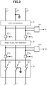
- the contactor 33 is provided at the secondary side of the remote shutoff breaker 32. This contactor 33 is electromagnetically actuated based on an open/close instruction from the monitoring device 60, interconnects the commercial power system with the home power system, or parallels off those from each other.
- the battery 52 is a battery including multiple cells filled with an electrolytic solution.
- AC voltage from the commercial power system is converted into DC voltage by the inverter 51, and is applied to the battery 52.
- the battery 52 stores an electrical charge.
- the DC voltage of the battery 52 is converted into AC voltage by the inverter 51, and is applied to the home power system.
- power is supplied to the home power system from the power storing unit 50.
- the power storing unit 50 also supplies power to the monitoring device 60.
- FIG. 6 is a flowchart illustrating an interconnecting process executed by the CPU 61 of the monitoring device 60.
- the interconnecting process will be explained below with reference to FIG. 6 .
- This interconnecting process is executed when the commercial power system is recovered from a blackout.
- the CPU 61 monitors the secondary-side voltage V2, and when the secondary-side voltage V2 is equal to or lower than the threshold value, determines that the remote shutoff breaker 32 has not been turned on (step S302: NO), and the process returns to the step S301.
- the processes in the steps S301, S302 are repeated until the determination result in the step S302 becomes positive.
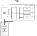
- the power supply switching device is formed by the monitoring device 60, the remote shutoff breaker 32, the contactor 33, and the voltage detecting transformers VT1, VT2.
- the monitoring device 60 checks whether or not the primary-side voltage V1 of the remote shutoff breaker 32 and the secondary-side voltage V2 thereof become the rated voltage (steps S301, S302). Subsequently, when both primary-side voltage V1 and secondary-side voltage V2 become the rated voltage (steps S301, S302: YES), the contactor 33 is actuated to interconnect the home power system with the commercial power system (step S304).
- the secondary-side voltage V2 becomes substantially zero.
- an interconnection of the home power system with the commercial power system despite the user's intention after the commercial power system recovers from a blackout can be suppressed.
- an interconnection of the home power system with the commercial power system and a charging despite the user's intension are avoidable. Therefore, the safety of the user can be ensured.
- the second embodiment is an embodiment according to the invention.
- the same or equivalent structure as that of the first embodiment will be denoted by the same reference numeral, and the explanation thereof will be omitted or simplified.
- the CPU 61 outputs in the step S303 a power storing instruction to the inverter 51 of the power storing unit 50. Hence, power supply to the home power system from the power storing unit 50 is terminated.
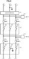
- the two switches 36 are connected in series. Hence, even if the contact of the one switch 36 is fused, the home power system can be paralleled off from the commercial power system.
- the present disclosure is, however, not limited to this case, and the switch board may be formed by equal to or greater than three switches 36 connected in series.
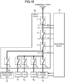
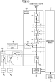
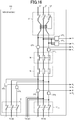
- FIG. 16 is a wiring diagram of the switch board 30D.
- the switch board 30D includes voltage detecting transformers VT1 1 , VT1 2 , and current transformers CT1 1 , CT1 2 , CT2 1 , CT2 2 , CT3 1 , CT3 2 .
- the direction from the commercial power system to each device of the home power system is defined as a positive direction.
- step S406 When the value of the secondary-side current I1 1 is compared with the value of the secondary-side current I2 2 and both values are different (step S406: NO), the monitoring device 60 compares the value of the secondary-side current I1 1 with a value obtained by multiplying the value of the secondary-side current I2 2 by -1 (step S408). Next, when both values are equal (step S408: YES), the monitoring device 60 determines that the directions of the current transformer CT1 1 and the current transformer CT2 2 are different but the connected power supply lines are proper (step S409).
- the manufacturing costs of the switch board can be reduced while improving the safety.
- the amount of metals utilized in the whole switch board can be reduced, which becomes a care for the global environment.
- the switch board when the casing of the switch board is formed of a plastic, the switch board can be made lightweight, and thus the degree of freedom for a disposition location can be further improved.
Landscapes
- Engineering & Computer Science (AREA)
- Power Engineering (AREA)
- Business, Economics & Management (AREA)
- Emergency Management (AREA)
- Supply And Distribution Of Alternating Current (AREA)
- Charge And Discharge Circuits For Batteries Or The Like (AREA)
Claims (11)
- Dispositif de commutation d'alimentation électrique comprenant :une première unité de commutation (33, 36, 37) pour déconnecter un stockage d'énergie (50) et une charge (40) d'un système d'alimentation et interconnecter le stockage d'énergie (50) et la charge (40) avec le système d'alimentation ;une seconde unité de commutation (32), qui est disposée sur le côté primaire de la première unité de commutation (33, 36, 37) et pour déconnecter le stockage d'énergie (50) et la charge (40) du système d'alimentation et interconnecter le stockage d'énergie (50) et la charge (40) avec le système d'alimentation ;un premier détecteur de tension (VT1) qui est disposé sur un côté primaire de la première unité de commutation (33, 36, 37) et sur un côté primaire de la seconde unité de commutation (32) et qui est apte à détecter une tension du système d'alimentation ; etun second détecteur de tension (VT2) qui est disposé entre la première unité de commutation (33, 36, 37) et la seconde unité de commutation (32), et qui est apte à détecter une tension du système d'alimentation ; etun système de commande (60) qui est configuré pouractionner la première unité de commutation (33, 36, 37) et la seconde unité de commutation (32) afin de déconnecter le stockage d'énergie (50) et la charge (40) du système d'alimentation en l'absence de détection de la tension du système d'alimentation par le premier détecteur de tension (VT1),déterminer que l'utilisateur a donné une instruction et actionner la première unité de commutation (33, 36, 37) pour interconnecter le stockage d'énergie (50) et la charge (40) avec le système d'alimentation, lorsque la première unité de commutation (33, 36, 37) déconnecte le stockage d'énergie (50) et la charge (40) du système d'alimentation et que le premier détecteur de tension (VT1) détecte la tension, et qu'ensuite un utilisateur actionne la seconde unité de commutation (32) pour interconnecter le stockage d'énergie (50) et la charge (40) avec le système d'alimentation et que le second détecteur de tension (VT2) détecte la tension du système d'alimentation.
- Dispositif de commutation d'alimentation électrique selon la revendication 1, caractérisé en ce que la première unité de commutation (33, 36, 37) est un commutateur de type à verrou (36).
- Dispositif de commutation d'alimentation électrique selon l'une quelconque des revendications 1 ou 2, caractérisé en ce que la première unité de commutation (33, 36, 37) est un interrupteur différentiel de sécurité (37).
- Dispositif de commutation d'alimentation électrique selon l'une quelconque des revendications 1 à 3, caractérisé en ce qu'il comprend en outre :un système de mesure de courant (CT2) qui est apte à mesurer un courant fourni à la charge (40) ; etune batterie solaire (80) connectée sur le côté primaire du système de mesure de courant (CT2).
- Dispositif de commutation d'alimentation électrique selon l'une quelconque des revendications 1 à 4, caractérisé en ce que le stockage d'énergie (50) est constitué d'alimentations électriques distribuées.
- Tableau de distribution (30) caractérisé en ce qu'il comprend :le dispositif de commutation d'alimentation électrique selon l'une quelconque des revendications 1 à 5 ; etun boîtier qui contient à l'intérieur le dispositif de commutation d'alimentation électrique.
- Tableau de distribution (30) selon la revendication 6, caractérisé en ce que le boîtier comprend :un premier boîtier qui contient à l'intérieur la première unité de commutation (33, 36, 37) ; etun second boîtier qui contient à l'intérieur un disjoncteur (37) qui est apte à débrancher individuellement la charge du système d'alimentation.
- Tableau de distribution (30) selon la revendication 6 ou 7, caractérisé en ce qu'il comprend en outre :un premier détecteur de courant (CT1) qui est apte à sélectionner un courant fourni au tableau de distribution (30) depuis le système d'alimentation ;un second détecteur de courant (CT2) qui est apte à détecter un courant fourni à la charge (40) et au stockage d'énergie (50) ; etun détecteur de condition de câblage qui est apte à comparer le courant détecté par le premier détecteur de courant (CT1) au courant détecté par le second détecteur de courant (CT2) et qui est apte à détecter des conditions de câblage respectives du premier détecteur de courant (CT1) et du second détecteur de courant (CT2).
- Dispositif de surveillance (60) comprenant :un premier système d'acquisition de tension qui est apte à acquérir la tension du système d'alimentation, à partir d'un premier détecteur de tension (VT1), qui est disposé sur un côté primaire d'une première unité de commutation (33, 36, 37) et sur un côté primaire de la seconde unité de commutation (32), pour déconnecter un stockage d'énergie (50) et une charge (40) d'un système d'alimentation et interconnecter le stockage d'énergie (50) et la charge (40) avec le système d'alimentation et qui est apte à détecter une tension du système d'alimentation ;un second système d'acquisition de tension qui est apte à acquérir la tension du système d'alimentation, à partir d'un second détecteur de tension (VT2) qui est disposé entre la première unité de commutation (33, 36, 37) et une seconde unité de commutation (32), disposée sur le côté primaire de la première unité de commutation (33, 36, 37), pour déconnecter le stockage d'énergie (50) et la charge (40) du système d'alimentation et interconnecter le stockage d'énergie (50) et la charge (40) avec le système d'alimentation, et qui est apte à détecter une tension du système d'alimentation ; etun système de commande qui est configuré pouractionner la première unité de commutation (33, 36, 37) et la seconde unité de commutation (32) afin de déconnecter le stockage d'énergie (50) et la charge (40) du système d'alimentation en l'absence de détection de la tension du système d'alimentation par le premier détecteur de tension (VT1),déterminer que l'utilisateur a donné une instruction et actionner la première unité de commutation (33, 36, 37) pour interconnecter le stockage d'énergie (50) et la charge (40) avec le système d'alimentation, lorsque la première unité de commutation (33, 36, 37) déconnecte le stockage d'énergie (50) et la charge (40) du système d'alimentation et que le premier détecteur de tension (VT1) détecte la tension, et qu'ensuite un utilisateur actionne la seconde unité de commutation (32) pour interconnecter le stockage d'énergie (50) et la charge (40) avec le système d'alimentation et que le second détecteur de tension (VT2) détecte la tension du système d'alimentation.
- Procédé de commutation de l'alimentation électrique comprenant :
une première étape d'acquisition de tension consistant à acquérir la tension du système d'alimentation, à partir d'un premier détecteur de tension (VT1) qui est disposé sur un côté primaire d'une première unité de commutation (33, 36, 37) et sur un côté primaire de la seconde unité de commutation (32), afin de déconnecter un stockage d'énergie (50) et une charge (40) d'un système d'alimentation et d'interconnecter le stockage d'énergie (50) et la charge (40) avec le système d'alimentation et qui détecte une tension du système d'alimentation ;une seconde étape d'acquisition de tension consistant à acquérir la tension du système d'alimentation, à partir d'un second détecteur de tension (VT2) qui est disposé entre la première unité de commutation (33, 36, 37) et une seconde unité de commutation (32), disposée sur le côté primaire de la première unité de commutation (33, 36, 37), pour déconnecter le stockage d'énergie (50) et la charge (40) du système d'alimentation et interconnecter le stockage d'énergie (50) et la charge (40) avec le système d'alimentation, et qui détecte une tension du système d'alimentation ; etune étape de commande consistant àactionner la première unité de commutation (33, 36, 37) et la seconde unité de commutation (32) pour déconnecter le stockage d'énergie (50) et la charge (40) du système d'alimentation en l'absence de détection de la tension du système d'alimentation par le premier détecteur de tension (VT1),déterminer que l'utilisateur a donné une instruction et actionner la première unité de commutation (33, 36, 37) pour interconnecter le stockage d'énergie (50) et la charge (40) avec le système d'alimentation, lorsque la première unité de commutation (33, 36, 37) déconnecte le stockage d'énergie (50) et la charge (40) du système d'alimentation et que le premier détecteur de tension (VT1) détecte la tension, et qu'ensuite, un utilisateur actionne la seconde unité de commutation (32) pour interconnecter le stockage d'énergie (50) et la charge (40) avec le système d'alimentation et que le second détecteur de tension (VT2) détecte la tension du système d'alimentation. - Programme pour amener un ordinateur à exécuter le procédé selon la revendication 10 dans le système selon la revendication 1.
Applications Claiming Priority (3)
| Application Number | Priority Date | Filing Date | Title |
|---|---|---|---|
| JP2012015680 | 2012-01-27 | ||
| JP2012166274A JP5497115B2 (ja) | 2012-01-27 | 2012-07-26 | 電源切替装置及び配電盤 |
| PCT/JP2013/051595 WO2013111858A1 (fr) | 2012-01-27 | 2013-01-25 | Dispositif de commutation d'alimentation électrique et tableau de commutation |
Publications (3)
| Publication Number | Publication Date |
|---|---|
| EP2808971A1 EP2808971A1 (fr) | 2014-12-03 |
| EP2808971A4 EP2808971A4 (fr) | 2016-04-20 |
| EP2808971B1 true EP2808971B1 (fr) | 2021-02-24 |
Family
ID=48873569
Family Applications (1)
| Application Number | Title | Priority Date | Filing Date |
|---|---|---|---|
| EP13740689.8A Not-in-force EP2808971B1 (fr) | 2012-01-27 | 2013-01-25 | Dispositif de commutation d'alimentation électrique et tableau de commutation |
Country Status (6)
| Country | Link |
|---|---|
| US (1) | US9825488B2 (fr) |
| EP (1) | EP2808971B1 (fr) |
| JP (1) | JP5497115B2 (fr) |
| KR (2) | KR20140108704A (fr) |
| CN (1) | CN104067475B (fr) |
| WO (1) | WO2013111858A1 (fr) |
Families Citing this family (26)
| Publication number | Priority date | Publication date | Assignee | Title |
|---|---|---|---|---|
| JP5497115B2 (ja) | 2012-01-27 | 2014-05-21 | 三菱電機株式会社 | 電源切替装置及び配電盤 |
| JP5734481B2 (ja) * | 2012-01-27 | 2015-06-17 | 三菱電機株式会社 | 監視装置、電力切替方法及びプログラム |
| EP2662697B1 (fr) | 2012-05-10 | 2014-06-04 | Omicron electronics GmbH | Dispositif de mesure destiné à contrôler un disjoncteur électrique |
| JP6241145B2 (ja) * | 2013-08-30 | 2017-12-06 | 株式会社オートネットワーク技術研究所 | 制御システム |
| JP2015053842A (ja) * | 2013-09-09 | 2015-03-19 | パナソニック株式会社 | 分散電源の接続装置 |
| JP6144616B2 (ja) * | 2013-12-24 | 2017-06-07 | 京セラ株式会社 | 電力制御装置、電力制御システム、および電力制御方法 |
| US20150333491A1 (en) * | 2014-05-13 | 2015-11-19 | Paul Cruz | Alternative energy bus bar by pass breaker |
| US9728972B2 (en) * | 2014-08-20 | 2017-08-08 | Qfe 002 Llc | Alternative energy bus bar by pass breaker, methods of use and installation |
| JP2015220791A (ja) * | 2014-05-14 | 2015-12-07 | 三菱電機株式会社 | 電力供給制御装置 |
| FR3021751B1 (fr) * | 2014-06-02 | 2018-01-05 | Ogga | Ensemble de contacteur et procede de gestion associe. |
| WO2016109675A1 (fr) * | 2015-01-02 | 2016-07-07 | Q Factory 33 Llc | Protection contre les surintensités de courant par dérivation de bus |
| US10749348B2 (en) * | 2015-10-28 | 2020-08-18 | Kyocera Corporation | Power control apparatus, control method for power control apparatus, power control system, and control method for power control system |
| US10684671B2 (en) | 2016-05-27 | 2020-06-16 | Qualcomm Incorporated | Adaptively controlling drive strength of multiplexed power from supply power rails in a power multiplexing system to a powered circuit |
| JP6758168B2 (ja) * | 2016-12-06 | 2020-09-23 | 三菱電機株式会社 | パワーコンディショナ |
| JP6338131B1 (ja) * | 2017-09-04 | 2018-06-06 | 日新電機株式会社 | 電源システム |
| JP7171174B2 (ja) * | 2017-09-05 | 2022-11-15 | エドワーズ株式会社 | 真空ポンプ及びモータ制御装置 |
| KR102484266B1 (ko) * | 2018-01-08 | 2023-01-02 | 삼성에스디아이 주식회사 | 에너지 저장 시스템용 비상 차단 회로 |
| KR102129682B1 (ko) * | 2018-06-18 | 2020-07-02 | 한국조선해양 주식회사 | Ess와 spdt를 이용한 발전기 재투입 시스템을 갖는 선박 |
| JP7176384B2 (ja) * | 2018-12-06 | 2022-11-22 | 住友電気工業株式会社 | 蓄電システム及び、電流センサの異常判定方法 |
| DE102018133319A1 (de) * | 2018-12-21 | 2020-06-25 | Rittal Gmbh & Co. Kg | Verfahren zur robotergestützten Verdrahtung von elektrischen Komponenten einer auf einer Montageplatte angeordneten elektrischen Schaltanlage |
| US11791615B2 (en) | 2019-02-25 | 2023-10-17 | Paul M. Cruz | Alternative energy interface, with power control system, multiple source combiner, and islanding |
| JP2020150787A (ja) * | 2019-02-28 | 2020-09-17 | ソーラーエッジ テクノロジーズ リミテッド | グリッド接続のためのリレーアレイ |
| JP6635411B2 (ja) * | 2019-03-25 | 2020-01-22 | Toto株式会社 | 手乾燥装置 |
| DE102020129918A1 (de) | 2020-11-12 | 2022-05-12 | Sma Solar Technology Ag | Vorrichtung und Verfahren zur Erdung eines Gleichspannungsnetzes |
| WO2023161951A1 (fr) * | 2022-02-25 | 2023-08-31 | Narayanan Surendran | Tableau de distribution protégé intégré à un système de distribution d'énergie de charge à basse tension |
| CN120879716B (zh) * | 2025-09-25 | 2025-12-30 | 南京赫曦电气有限公司 | 发电车并网解列不停电作业装置、不停电作业系统及方法 |
Citations (4)
| Publication number | Priority date | Publication date | Assignee | Title |
|---|---|---|---|---|
| JPH07336896A (ja) * | 1994-06-03 | 1995-12-22 | Nissin Electric Co Ltd | 分散型系統連系装置 |
| EP0748991A2 (fr) * | 1995-06-13 | 1996-12-18 | Sanyo Electric Co. Ltd | Climatisation avec générateur solaire |
| WO2008138016A1 (fr) * | 2007-05-08 | 2008-11-13 | American Power Conversion Corporation | Gestion de l'énergie d'une source alternative |
| US20110051325A1 (en) * | 2009-09-02 | 2011-03-03 | Kawasaki Michikata | Power supply system |
Family Cites Families (28)
| Publication number | Priority date | Publication date | Assignee | Title |
|---|---|---|---|---|
| JPH05508069A (ja) * | 1990-06-25 | 1993-11-11 | ザ・サウス・イースト・クイーンズランド・エレクトリシティ・ボード | 配電盤 |
| JP3428005B2 (ja) * | 1994-08-18 | 2003-07-22 | 日新電機株式会社 | 分散型連系システムの運転制御方法 |
| JP3633123B2 (ja) | 1996-07-31 | 2005-03-30 | 松下電工株式会社 | 分散電源システム |
| GB2394130B (en) | 1999-06-11 | 2004-05-26 | Electric Power Res Inst | Meter collar with interface for connecting on-site power source and the interface itself |
| US6282104B1 (en) * | 2000-03-14 | 2001-08-28 | Applied Power Corporation | DC injection and even harmonics control system |
| JP2002252928A (ja) * | 2001-02-26 | 2002-09-06 | Miki Denki Kk | 分散電源システム及びその制御・保護装置 |
| JP4080714B2 (ja) | 2001-09-07 | 2008-04-23 | 株式会社東芝 | 発電装置及びこの発電装置を用いた電源供給システム |
| JP3767816B2 (ja) * | 2002-10-07 | 2006-04-19 | デンセイ・ラムダ株式会社 | 無停電電源システムの監視方法、無停電電源システム、無停電電源装置および配電盤 |
| JP4253700B2 (ja) * | 2002-12-16 | 2009-04-15 | 富士電機機器制御株式会社 | 漏電遮断器 |
| JP4424912B2 (ja) | 2003-02-07 | 2010-03-03 | 大阪瓦斯株式会社 | 分散型発電システム |
| JP4160919B2 (ja) * | 2004-03-24 | 2008-10-08 | シャープ株式会社 | インバータ装置 |
| JP4619298B2 (ja) | 2006-02-02 | 2011-01-26 | シャープ株式会社 | 電力変換装置 |
| AU2007212381A1 (en) * | 2006-02-06 | 2007-08-16 | Optimal Innovations Inc. | Management of high-availability power infrastructures |
| JP2008206266A (ja) * | 2007-02-19 | 2008-09-04 | Honda Motor Co Ltd | コージェネレーション装置 |
| EP1965483B1 (fr) | 2007-02-27 | 2015-07-08 | SMA Solar Technology AG | Circuit pour la connexion d'une installation de génération d'énegie au réseau électrique |
| AU2008224840B2 (en) * | 2007-03-14 | 2013-10-03 | Zonit Structured Solutions, Llc | Smart NEMA outlets and associated networks |
| US9184592B2 (en) * | 2008-08-05 | 2015-11-10 | Lennox Industries Inc. | Utility-interactive inverter system architecture and method of operation thereof |
| JP5382767B2 (ja) * | 2008-10-03 | 2014-01-08 | 一般財団法人電力中央研究所 | 燃料電池発電システム |
| KR101078905B1 (ko) | 2009-05-21 | 2011-11-01 | 엘에스산전 주식회사 | 지능형 분전반 |
| JP2011050131A (ja) | 2009-08-25 | 2011-03-10 | Hot Plan:Kk | 住宅用給電システム及びそれを構成する給電制御装置 |
| KR101156533B1 (ko) | 2009-12-23 | 2012-07-03 | 삼성에스디아이 주식회사 | 에너지 저장 시스템 및 이의 제어 방법 |
| US8492928B2 (en) * | 2010-03-18 | 2013-07-23 | American Power Conversion Corporation | AC-to-DC conversion |
| US8547109B2 (en) * | 2010-07-19 | 2013-10-01 | The Southern Company | Capacitor monitoring systems and methods of metering and monitoring capacitor bank |
| JP5819602B2 (ja) * | 2010-11-29 | 2015-11-24 | Jx日鉱日石エネルギー株式会社 | 地絡検出装置、地絡検出方法、太陽光発電システム、及び地絡検出プログラム |
| EP2463674B1 (fr) * | 2010-12-08 | 2013-07-03 | Siemens Aktiengesellschaft | Agencement et procédé de test d'un système de génération d'alimentation électrique |
| US9148016B2 (en) * | 2011-05-26 | 2015-09-29 | Pika Energy Inc. | DC microgrid for interconnecting distributed electricity generation, loads, and storage |
| JPWO2013015225A1 (ja) * | 2011-07-22 | 2015-02-23 | 京セラ株式会社 | 制御装置及び電力制御方法 |
| JP5497115B2 (ja) | 2012-01-27 | 2014-05-21 | 三菱電機株式会社 | 電源切替装置及び配電盤 |
-
2012
- 2012-07-26 JP JP2012166274A patent/JP5497115B2/ja not_active Expired - Fee Related
-
2013
- 2013-01-25 US US14/370,662 patent/US9825488B2/en not_active Expired - Fee Related
- 2013-01-25 WO PCT/JP2013/051595 patent/WO2013111858A1/fr not_active Ceased
- 2013-01-25 KR KR1020147020809A patent/KR20140108704A/ko not_active Ceased
- 2013-01-25 CN CN201380006632.2A patent/CN104067475B/zh not_active Expired - Fee Related
- 2013-01-25 EP EP13740689.8A patent/EP2808971B1/fr not_active Not-in-force
- 2013-01-25 KR KR1020167025979A patent/KR101741386B1/ko not_active Expired - Fee Related
Patent Citations (4)
| Publication number | Priority date | Publication date | Assignee | Title |
|---|---|---|---|---|
| JPH07336896A (ja) * | 1994-06-03 | 1995-12-22 | Nissin Electric Co Ltd | 分散型系統連系装置 |
| EP0748991A2 (fr) * | 1995-06-13 | 1996-12-18 | Sanyo Electric Co. Ltd | Climatisation avec générateur solaire |
| WO2008138016A1 (fr) * | 2007-05-08 | 2008-11-13 | American Power Conversion Corporation | Gestion de l'énergie d'une source alternative |
| US20110051325A1 (en) * | 2009-09-02 | 2011-03-03 | Kawasaki Michikata | Power supply system |
Also Published As
| Publication number | Publication date |
|---|---|
| EP2808971A1 (fr) | 2014-12-03 |
| EP2808971A4 (fr) | 2016-04-20 |
| US9825488B2 (en) | 2017-11-21 |
| WO2013111858A1 (fr) | 2013-08-01 |
| KR20140108704A (ko) | 2014-09-12 |
| KR20160116350A (ko) | 2016-10-07 |
| US20140339900A1 (en) | 2014-11-20 |
| JP5497115B2 (ja) | 2014-05-21 |
| CN104067475A (zh) | 2014-09-24 |
| CN104067475B (zh) | 2017-09-26 |
| JP2013176278A (ja) | 2013-09-05 |
| KR101741386B1 (ko) | 2017-05-29 |
Similar Documents
| Publication | Publication Date | Title |
|---|---|---|
| EP2808971B1 (fr) | Dispositif de commutation d'alimentation électrique et tableau de commutation | |
| JP5781012B2 (ja) | 電源切替装置及び住宅 | |
| JP6095407B2 (ja) | 電力供給システム | |
| EP3370334B1 (fr) | Dispositif de contrôle de puissance, procédé de contrôle pour dispositif de contrôle de puissance, système de contrôle de puissance et procédé de contrôle pour système de contrôle de puissance | |
| JP6503095B2 (ja) | 充放電装置 | |
| CN106684824B (zh) | 一种基于电流互感器断线的变压器差动保护方法及装置 | |
| JP7251908B2 (ja) | 充放電装置及び電源切替システム | |
| JP2008148505A (ja) | 過負荷対策電力補償装置 | |
| JP2015006044A (ja) | 電力供給装置及び電力供給システム | |
| CN109429542A (zh) | 功率转换装置和确定断路装置的操作状态的方法 | |
| JP5734481B2 (ja) | 監視装置、電力切替方法及びプログラム | |
| JP6272971B2 (ja) | 電源切替装置及び住宅 | |
| JP5858236B2 (ja) | 蓄電池システム | |
| WO2023086518A2 (fr) | Systèmes et procédés pour onduleur électrique et intégration de commande de charge intelligente | |
| EP2618441A1 (fr) | Procédé de fonctionnement d'un module de disjoncteur intégré pour système d'énergie solaire | |
| CN111208369A (zh) | 核电厂直流系统短路电流的计算方法及装置 | |
| JP4227552B2 (ja) | 単独運転防止方法およびそれを用いた単独運転防止装置 | |
| EP2732472A1 (fr) | Système permettant de mettre des centrales solaires en situation sûre | |
| JP2023053370A (ja) | 充放電装置 | |
| KR20140134496A (ko) | 신재생에너지 발전전력을 이용하여 운전효율을 극대화한 고ㆍ저압 배전반 및 그 제어방법 |
Legal Events
| Date | Code | Title | Description |
|---|---|---|---|
| PUAI | Public reference made under article 153(3) epc to a published international application that has entered the european phase |
Free format text: ORIGINAL CODE: 0009012 |
|
| 17P | Request for examination filed |
Effective date: 20140722 |
|
| AK | Designated contracting states |
Kind code of ref document: A1 Designated state(s): AL AT BE BG CH CY CZ DE DK EE ES FI FR GB GR HR HU IE IS IT LI LT LU LV MC MK MT NL NO PL PT RO RS SE SI SK SM TR |
|
| DAX | Request for extension of the european patent (deleted) | ||
| RA4 | Supplementary search report drawn up and despatched (corrected) |
Effective date: 20160318 |
|
| RIC1 | Information provided on ipc code assigned before grant |
Ipc: H02J 3/38 20060101AFI20160314BHEP Ipc: H02J 9/06 20060101ALI20160314BHEP |
|
| STAA | Information on the status of an ep patent application or granted ep patent |
Free format text: STATUS: EXAMINATION IS IN PROGRESS |
|
| 17Q | First examination report despatched |
Effective date: 20170817 |
|
| REG | Reference to a national code |
Ref country code: DE Ref legal event code: R079 Ref document number: 602013075856 Country of ref document: DE Free format text: PREVIOUS MAIN CLASS: H02J0003380000 Ipc: H02H0003060000 |
|
| RIC1 | Information provided on ipc code assigned before grant |
Ipc: H02H 3/06 20060101AFI20200617BHEP Ipc: H02J 9/06 20060101ALI20200617BHEP Ipc: H02J 3/38 20060101ALI20200617BHEP |
|
| GRAP | Despatch of communication of intention to grant a patent |
Free format text: ORIGINAL CODE: EPIDOSNIGR1 |
|
| STAA | Information on the status of an ep patent application or granted ep patent |
Free format text: STATUS: GRANT OF PATENT IS INTENDED |
|
| INTG | Intention to grant announced |
Effective date: 20200921 |
|
| GRAS | Grant fee paid |
Free format text: ORIGINAL CODE: EPIDOSNIGR3 |
|
| GRAA | (expected) grant |
Free format text: ORIGINAL CODE: 0009210 |
|
| STAA | Information on the status of an ep patent application or granted ep patent |
Free format text: STATUS: THE PATENT HAS BEEN GRANTED |
|
| AK | Designated contracting states |
Kind code of ref document: B1 Designated state(s): AL AT BE BG CH CY CZ DE DK EE ES FI FR GB GR HR HU IE IS IT LI LT LU LV MC MK MT NL NO PL PT RO RS SE SI SK SM TR |
|
| REG | Reference to a national code |
Ref country code: GB Ref legal event code: FG4D |
|
| REG | Reference to a national code |
Ref country code: CH Ref legal event code: EP |
|
| REG | Reference to a national code |
Ref country code: AT Ref legal event code: REF Ref document number: 1365690 Country of ref document: AT Kind code of ref document: T Effective date: 20210315 |
|
| REG | Reference to a national code |
Ref country code: IE Ref legal event code: FG4D |
|
| REG | Reference to a national code |
Ref country code: DE Ref legal event code: R096 Ref document number: 602013075856 Country of ref document: DE |
|
| REG | Reference to a national code |
Ref country code: LT Ref legal event code: MG9D |
|
| REG | Reference to a national code |
Ref country code: NL Ref legal event code: MP Effective date: 20210224 |
|
| PG25 | Lapsed in a contracting state [announced via postgrant information from national office to epo] |
Ref country code: NO Free format text: LAPSE BECAUSE OF FAILURE TO SUBMIT A TRANSLATION OF THE DESCRIPTION OR TO PAY THE FEE WITHIN THE PRESCRIBED TIME-LIMIT Effective date: 20210524 Ref country code: BG Free format text: LAPSE BECAUSE OF FAILURE TO SUBMIT A TRANSLATION OF THE DESCRIPTION OR TO PAY THE FEE WITHIN THE PRESCRIBED TIME-LIMIT Effective date: 20210524 Ref country code: FI Free format text: LAPSE BECAUSE OF FAILURE TO SUBMIT A TRANSLATION OF THE DESCRIPTION OR TO PAY THE FEE WITHIN THE PRESCRIBED TIME-LIMIT Effective date: 20210224 Ref country code: GR Free format text: LAPSE BECAUSE OF FAILURE TO SUBMIT A TRANSLATION OF THE DESCRIPTION OR TO PAY THE FEE WITHIN THE PRESCRIBED TIME-LIMIT Effective date: 20210525 Ref country code: HR Free format text: LAPSE BECAUSE OF FAILURE TO SUBMIT A TRANSLATION OF THE DESCRIPTION OR TO PAY THE FEE WITHIN THE PRESCRIBED TIME-LIMIT Effective date: 20210224 Ref country code: LT Free format text: LAPSE BECAUSE OF FAILURE TO SUBMIT A TRANSLATION OF THE DESCRIPTION OR TO PAY THE FEE WITHIN THE PRESCRIBED TIME-LIMIT Effective date: 20210224 Ref country code: PT Free format text: LAPSE BECAUSE OF FAILURE TO SUBMIT A TRANSLATION OF THE DESCRIPTION OR TO PAY THE FEE WITHIN THE PRESCRIBED TIME-LIMIT Effective date: 20210624 |
|
| REG | Reference to a national code |
Ref country code: AT Ref legal event code: MK05 Ref document number: 1365690 Country of ref document: AT Kind code of ref document: T Effective date: 20210224 |
|
| PG25 | Lapsed in a contracting state [announced via postgrant information from national office to epo] |
Ref country code: SE Free format text: LAPSE BECAUSE OF FAILURE TO SUBMIT A TRANSLATION OF THE DESCRIPTION OR TO PAY THE FEE WITHIN THE PRESCRIBED TIME-LIMIT Effective date: 20210224 Ref country code: NL Free format text: LAPSE BECAUSE OF FAILURE TO SUBMIT A TRANSLATION OF THE DESCRIPTION OR TO PAY THE FEE WITHIN THE PRESCRIBED TIME-LIMIT Effective date: 20210224 Ref country code: RS Free format text: LAPSE BECAUSE OF FAILURE TO SUBMIT A TRANSLATION OF THE DESCRIPTION OR TO PAY THE FEE WITHIN THE PRESCRIBED TIME-LIMIT Effective date: 20210224 Ref country code: PL Free format text: LAPSE BECAUSE OF FAILURE TO SUBMIT A TRANSLATION OF THE DESCRIPTION OR TO PAY THE FEE WITHIN THE PRESCRIBED TIME-LIMIT Effective date: 20210224 Ref country code: LV Free format text: LAPSE BECAUSE OF FAILURE TO SUBMIT A TRANSLATION OF THE DESCRIPTION OR TO PAY THE FEE WITHIN THE PRESCRIBED TIME-LIMIT Effective date: 20210224 |
|
| PG25 | Lapsed in a contracting state [announced via postgrant information from national office to epo] |
Ref country code: IS Free format text: LAPSE BECAUSE OF FAILURE TO SUBMIT A TRANSLATION OF THE DESCRIPTION OR TO PAY THE FEE WITHIN THE PRESCRIBED TIME-LIMIT Effective date: 20210624 |
|
| PG25 | Lapsed in a contracting state [announced via postgrant information from national office to epo] |
Ref country code: EE Free format text: LAPSE BECAUSE OF FAILURE TO SUBMIT A TRANSLATION OF THE DESCRIPTION OR TO PAY THE FEE WITHIN THE PRESCRIBED TIME-LIMIT Effective date: 20210224 Ref country code: CZ Free format text: LAPSE BECAUSE OF FAILURE TO SUBMIT A TRANSLATION OF THE DESCRIPTION OR TO PAY THE FEE WITHIN THE PRESCRIBED TIME-LIMIT Effective date: 20210224 Ref country code: SM Free format text: LAPSE BECAUSE OF FAILURE TO SUBMIT A TRANSLATION OF THE DESCRIPTION OR TO PAY THE FEE WITHIN THE PRESCRIBED TIME-LIMIT Effective date: 20210224 Ref country code: AT Free format text: LAPSE BECAUSE OF FAILURE TO SUBMIT A TRANSLATION OF THE DESCRIPTION OR TO PAY THE FEE WITHIN THE PRESCRIBED TIME-LIMIT Effective date: 20210224 |
|
| REG | Reference to a national code |
Ref country code: DE Ref legal event code: R097 Ref document number: 602013075856 Country of ref document: DE |
|
| PG25 | Lapsed in a contracting state [announced via postgrant information from national office to epo] |
Ref country code: SK Free format text: LAPSE BECAUSE OF FAILURE TO SUBMIT A TRANSLATION OF THE DESCRIPTION OR TO PAY THE FEE WITHIN THE PRESCRIBED TIME-LIMIT Effective date: 20210224 Ref country code: RO Free format text: LAPSE BECAUSE OF FAILURE TO SUBMIT A TRANSLATION OF THE DESCRIPTION OR TO PAY THE FEE WITHIN THE PRESCRIBED TIME-LIMIT Effective date: 20210224 Ref country code: ES Free format text: LAPSE BECAUSE OF FAILURE TO SUBMIT A TRANSLATION OF THE DESCRIPTION OR TO PAY THE FEE WITHIN THE PRESCRIBED TIME-LIMIT Effective date: 20210224 Ref country code: DK Free format text: LAPSE BECAUSE OF FAILURE TO SUBMIT A TRANSLATION OF THE DESCRIPTION OR TO PAY THE FEE WITHIN THE PRESCRIBED TIME-LIMIT Effective date: 20210224 |
|
| PLBE | No opposition filed within time limit |
Free format text: ORIGINAL CODE: 0009261 |
|
| STAA | Information on the status of an ep patent application or granted ep patent |
Free format text: STATUS: NO OPPOSITION FILED WITHIN TIME LIMIT |
|
| PG25 | Lapsed in a contracting state [announced via postgrant information from national office to epo] |
Ref country code: AL Free format text: LAPSE BECAUSE OF FAILURE TO SUBMIT A TRANSLATION OF THE DESCRIPTION OR TO PAY THE FEE WITHIN THE PRESCRIBED TIME-LIMIT Effective date: 20210224 |
|
| 26N | No opposition filed |
Effective date: 20211125 |
|
| PG25 | Lapsed in a contracting state [announced via postgrant information from national office to epo] |
Ref country code: SI Free format text: LAPSE BECAUSE OF FAILURE TO SUBMIT A TRANSLATION OF THE DESCRIPTION OR TO PAY THE FEE WITHIN THE PRESCRIBED TIME-LIMIT Effective date: 20210224 |
|
| PG25 | Lapsed in a contracting state [announced via postgrant information from national office to epo] |
Ref country code: IT Free format text: LAPSE BECAUSE OF FAILURE TO SUBMIT A TRANSLATION OF THE DESCRIPTION OR TO PAY THE FEE WITHIN THE PRESCRIBED TIME-LIMIT Effective date: 20210224 |
|
| PG25 | Lapsed in a contracting state [announced via postgrant information from national office to epo] |
Ref country code: IS Free format text: LAPSE BECAUSE OF FAILURE TO SUBMIT A TRANSLATION OF THE DESCRIPTION OR TO PAY THE FEE WITHIN THE PRESCRIBED TIME-LIMIT Effective date: 20210624 |
|
| PG25 | Lapsed in a contracting state [announced via postgrant information from national office to epo] |
Ref country code: MC Free format text: LAPSE BECAUSE OF FAILURE TO SUBMIT A TRANSLATION OF THE DESCRIPTION OR TO PAY THE FEE WITHIN THE PRESCRIBED TIME-LIMIT Effective date: 20210224 |
|
| REG | Reference to a national code |
Ref country code: CH Ref legal event code: PL |
|
| REG | Reference to a national code |
Ref country code: BE Ref legal event code: MM Effective date: 20220131 |
|
| PG25 | Lapsed in a contracting state [announced via postgrant information from national office to epo] |
Ref country code: LU Free format text: LAPSE BECAUSE OF NON-PAYMENT OF DUE FEES Effective date: 20220125 |
|
| PG25 | Lapsed in a contracting state [announced via postgrant information from national office to epo] |
Ref country code: BE Free format text: LAPSE BECAUSE OF NON-PAYMENT OF DUE FEES Effective date: 20220131 |
|
| PG25 | Lapsed in a contracting state [announced via postgrant information from national office to epo] |
Ref country code: LI Free format text: LAPSE BECAUSE OF NON-PAYMENT OF DUE FEES Effective date: 20220131 Ref country code: CH Free format text: LAPSE BECAUSE OF NON-PAYMENT OF DUE FEES Effective date: 20220131 |
|
| PG25 | Lapsed in a contracting state [announced via postgrant information from national office to epo] |
Ref country code: IE Free format text: LAPSE BECAUSE OF NON-PAYMENT OF DUE FEES Effective date: 20220125 |
|
| P01 | Opt-out of the competence of the unified patent court (upc) registered |
Effective date: 20230512 |
|
| PGFP | Annual fee paid to national office [announced via postgrant information from national office to epo] |
Ref country code: GB Payment date: 20231207 Year of fee payment: 12 |
|
| PGFP | Annual fee paid to national office [announced via postgrant information from national office to epo] |
Ref country code: FR Payment date: 20231212 Year of fee payment: 12 |
|
| PG25 | Lapsed in a contracting state [announced via postgrant information from national office to epo] |
Ref country code: HU Free format text: LAPSE BECAUSE OF FAILURE TO SUBMIT A TRANSLATION OF THE DESCRIPTION OR TO PAY THE FEE WITHIN THE PRESCRIBED TIME-LIMIT; INVALID AB INITIO Effective date: 20130125 |
|
| PG25 | Lapsed in a contracting state [announced via postgrant information from national office to epo] |
Ref country code: MK Free format text: LAPSE BECAUSE OF FAILURE TO SUBMIT A TRANSLATION OF THE DESCRIPTION OR TO PAY THE FEE WITHIN THE PRESCRIBED TIME-LIMIT Effective date: 20210224 Ref country code: CY Free format text: LAPSE BECAUSE OF FAILURE TO SUBMIT A TRANSLATION OF THE DESCRIPTION OR TO PAY THE FEE WITHIN THE PRESCRIBED TIME-LIMIT Effective date: 20210224 |
|
| PGFP | Annual fee paid to national office [announced via postgrant information from national office to epo] |
Ref country code: DE Payment date: 20231128 Year of fee payment: 12 |
|
| PG25 | Lapsed in a contracting state [announced via postgrant information from national office to epo] |
Ref country code: TR Free format text: LAPSE BECAUSE OF FAILURE TO SUBMIT A TRANSLATION OF THE DESCRIPTION OR TO PAY THE FEE WITHIN THE PRESCRIBED TIME-LIMIT Effective date: 20210224 |
|
| PG25 | Lapsed in a contracting state [announced via postgrant information from national office to epo] |
Ref country code: MT Free format text: LAPSE BECAUSE OF FAILURE TO SUBMIT A TRANSLATION OF THE DESCRIPTION OR TO PAY THE FEE WITHIN THE PRESCRIBED TIME-LIMIT Effective date: 20210224 |
|
| REG | Reference to a national code |
Ref country code: DE Ref legal event code: R119 Ref document number: 602013075856 Country of ref document: DE |
|
| GBPC | Gb: european patent ceased through non-payment of renewal fee |
Effective date: 20250125 |
|
| PG25 | Lapsed in a contracting state [announced via postgrant information from national office to epo] |
Ref country code: DE Free format text: LAPSE BECAUSE OF NON-PAYMENT OF DUE FEES Effective date: 20250801 |
|
| PG25 | Lapsed in a contracting state [announced via postgrant information from national office to epo] |
Ref country code: GB Free format text: LAPSE BECAUSE OF NON-PAYMENT OF DUE FEES Effective date: 20250125 |
|
| PG25 | Lapsed in a contracting state [announced via postgrant information from national office to epo] |
Ref country code: FR Free format text: LAPSE BECAUSE OF NON-PAYMENT OF DUE FEES Effective date: 20250131 |