EP2808973A1 - Circuit d'égalisation de tension de cellule de batterie - Google Patents
Circuit d'égalisation de tension de cellule de batterie Download PDFInfo
- Publication number
- EP2808973A1 EP2808973A1 EP12866674.0A EP12866674A EP2808973A1 EP 2808973 A1 EP2808973 A1 EP 2808973A1 EP 12866674 A EP12866674 A EP 12866674A EP 2808973 A1 EP2808973 A1 EP 2808973A1
- Authority
- EP
- European Patent Office
- Prior art keywords
- battery cell
- battery
- switch
- path
- fuse
- Prior art date
- Legal status (The legal status is an assumption and is not a legal conclusion. Google has not performed a legal analysis and makes no representation as to the accuracy of the status listed.)
- Withdrawn
Links
Images




Classifications
-
- H—ELECTRICITY
- H01—ELECTRIC ELEMENTS
- H01M—PROCESSES OR MEANS, e.g. BATTERIES, FOR THE DIRECT CONVERSION OF CHEMICAL ENERGY INTO ELECTRICAL ENERGY
- H01M10/00—Secondary cells; Manufacture thereof
- H01M10/42—Methods or arrangements for servicing or maintenance of secondary cells or secondary half-cells
- H01M10/44—Methods for charging or discharging
-
- H—ELECTRICITY
- H01—ELECTRIC ELEMENTS
- H01M—PROCESSES OR MEANS, e.g. BATTERIES, FOR THE DIRECT CONVERSION OF CHEMICAL ENERGY INTO ELECTRICAL ENERGY
- H01M10/00—Secondary cells; Manufacture thereof
- H01M10/42—Methods or arrangements for servicing or maintenance of secondary cells or secondary half-cells
- H01M10/48—Accumulators combined with arrangements for measuring, testing or indicating the condition of cells, e.g. the level or density of the electrolyte
-
- H—ELECTRICITY
- H02—GENERATION; CONVERSION OR DISTRIBUTION OF ELECTRIC POWER
- H02J—ELECTRIC POWER NETWORKS; CIRCUIT ARRANGEMENTS OR SYSTEMS FOR SUPPLYING OR DISTRIBUTING ELECTRIC POWER; SYSTEMS FOR STORING ELECTRIC ENERGY
- H02J7/00—Circuit arrangements for charging or discharging batteries or for supplying loads from batteries
- H02J7/50—Circuit arrangements for charging or discharging batteries or for supplying loads from batteries acting upon multiple batteries simultaneously or sequentially
- H02J7/52—Circuit arrangements for charging or discharging batteries or for supplying loads from batteries acting upon multiple batteries simultaneously or sequentially for charge balancing, e.g. equalisation of charge between batteries
- H02J7/56—Active balancing, e.g. using capacitor-based, inductor-based or DC-DC converters
-
- H—ELECTRICITY
- H02—GENERATION; CONVERSION OR DISTRIBUTION OF ELECTRIC POWER
- H02J—ELECTRIC POWER NETWORKS; CIRCUIT ARRANGEMENTS OR SYSTEMS FOR SUPPLYING OR DISTRIBUTING ELECTRIC POWER; SYSTEMS FOR STORING ELECTRIC ENERGY
- H02J7/00—Circuit arrangements for charging or discharging batteries or for supplying loads from batteries
- H02J7/60—Circuit arrangements for charging or discharging batteries or for supplying loads from batteries including safety or protection arrangements
- H02J7/62—Circuit arrangements for charging or discharging batteries or for supplying loads from batteries including safety or protection arrangements against overcurrent
-
- H—ELECTRICITY
- H02—GENERATION; CONVERSION OR DISTRIBUTION OF ELECTRIC POWER
- H02J—ELECTRIC POWER NETWORKS; CIRCUIT ARRANGEMENTS OR SYSTEMS FOR SUPPLYING OR DISTRIBUTING ELECTRIC POWER; SYSTEMS FOR STORING ELECTRIC ENERGY
- H02J7/00—Circuit arrangements for charging or discharging batteries or for supplying loads from batteries
- H02J7/865—Battery or charger load switching, e.g. concurrent charging and load supply
-
- Y—GENERAL TAGGING OF NEW TECHNOLOGICAL DEVELOPMENTS; GENERAL TAGGING OF CROSS-SECTIONAL TECHNOLOGIES SPANNING OVER SEVERAL SECTIONS OF THE IPC; TECHNICAL SUBJECTS COVERED BY FORMER USPC CROSS-REFERENCE ART COLLECTIONS [XRACs] AND DIGESTS
- Y02—TECHNOLOGIES OR APPLICATIONS FOR MITIGATION OR ADAPTATION AGAINST CLIMATE CHANGE
- Y02E—REDUCTION OF GREENHOUSE GAS [GHG] EMISSIONS, RELATED TO ENERGY GENERATION, TRANSMISSION OR DISTRIBUTION
- Y02E60/00—Enabling technologies; Technologies with a potential or indirect contribution to GHG emissions mitigation
- Y02E60/10—Energy storage using batteries
-
- Y—GENERAL TAGGING OF NEW TECHNOLOGICAL DEVELOPMENTS; GENERAL TAGGING OF CROSS-SECTIONAL TECHNOLOGIES SPANNING OVER SEVERAL SECTIONS OF THE IPC; TECHNICAL SUBJECTS COVERED BY FORMER USPC CROSS-REFERENCE ART COLLECTIONS [XRACs] AND DIGESTS
- Y02—TECHNOLOGIES OR APPLICATIONS FOR MITIGATION OR ADAPTATION AGAINST CLIMATE CHANGE
- Y02T—CLIMATE CHANGE MITIGATION TECHNOLOGIES RELATED TO TRANSPORTATION
- Y02T10/00—Road transport of goods or passengers
- Y02T10/60—Other road transportation technologies with climate change mitigation effect
- Y02T10/70—Energy storage systems for electromobility, e.g. batteries
Definitions
- the present invention relates to a circuit that equalizes voltages of a plurality of battery cells that are connected in series.
- the output voltage (or the electricity remaining in the battery cell) may sometimes vary from one battery cell to another.
- the above batteries are implemented in an electric car or the like, discharging and charging are repeated for driving the motor and for regenerating electricity, which sometimes leads to variations in voltages between battery cells.
- Variations in voltages between battery cells may accelerate the deterioration of some of the battery cells and may also cause a decrease in the efficiency of the entire battery.
- variations in voltages between battery cells can be caused by production variations, degradation due to aging, etc. of battery cells. Accordingly, techniques that equalize voltages of a plurality of battery cells have conventionally been proposed or practiced.
- FIG. 8 shows an example of a conventional battery cell voltage equalization circuit.
- a battery 100 includes two rechargeable battery cells B1 and B2.
- the battery cells B1 and B2 are connected to each other in series.
- a load 110 is connected to the battery 100.
- the battery cell voltage equalization circuit includes an inductor L, switches S1 and S2, driver circuits D1 and D2, and a battery controller 10 as shown in FIG. 8 .
- the battery controller 10 monitors the voltages of the battery cells B1 and B2. In the explanations below, it is assumed that the voltage of the battery cell B1 is higher than that of the battery cell B2.
- the battery controller 10 generates a pulse string signal having a prescribed duty when the battery controller 10 performs a cell balance operation, which equalizes the voltages of the battery cells B1 and B2.
- the driver circuit D1 is an inversion driver while the driver circuit D2 is a non-inversion driver. Accordingly, when the battery controller 10 has output a pulse string signal, the switches S1 and s2 are controlled to an ON state alternately. In other words, when the switch S1 is controlled to an ON state, the switch S2 is controlled to an OFF state, whereas when the switch S1 is controlled in an OFF state, the switch S2 is controlled to an ON state.
- Patent Documents 1 through 5 are known.
- an overcurrent may occur in the following situations.
- a battery cell voltage equalization circuit equalizes the voltages of a first rechargeable battery cell and a second rechargeable battery cell that are connected in series.
- the battery cell voltage equalization circuit includes a first switch that is electrically connected to the positive electrode of the first battery cell via a first path, is electrically connected to the negative electrode of the first battery cell via a second path, and electrically connects or disconnects the first path and the second path; a second switch that is electrically connected to the positive electrode of the second battery cell via the second path, is electrically connected to the negative electrode of the second battery cell via a third path, and electrically connects or disconnects the second path and the third path; an inductor that is provided in the second path; and a fuse that is provided in at least one of the first through third paths.
- the first and second battery cells are protected from an overcurrent that would be caused by a failure in which the first and second switches enter an ON state simultaneously.
- the first and second switches constituting the battery cell voltage equalization circuit are also protected from the overcurrents.
- fuses in two of the first through third paths, respectively.
- the first and second battery cells are protected from an overcurrent even when one of the electric current flowing between the positive and negative electrodes of the first battery cell via the first switch and the inductor, the electric current flowing between the positive and negative electrodes of the second battery cell via the second switch and the inductor, and the electric current flowing between the positive electrode of the first battery cell and the negative electrode of the second battery cell via the first and second switches has become an overcurrent because one of the fuses blows.
- the fuse is provided for example between the negative electrode of the first battery cell, the positive electrode of the second battery cell, and the inductor.
- the battery cell voltage equalization circuit having the above configuration may include a monitoring unit that monitors the voltage between both ends of the first switch, the voltage between both ends of the second switch, and an electric current flowing via the inductor, and a detection unit that detects disconnection of the fuse on the basis of results of the monitoring performed by the monitoring unit.
- the present invention it is possible to protect a battery cell and a battery cell voltage equalization circuit from an overcurrent in the battery cell voltage equalization circuit that equalizes the voltages of a plurality of the battery cells that are connected in series.
- FIG. 1 shows a configuration of a battery cell voltage equalization circuit according to an embodiment of the present invention
- FIG. 1 shows a configuration of a battery cell voltage equalization circuit according to an embodiment of the present invention.
- a battery cell voltage equalization circuit 1 according to an embodiment equalizes voltages of a plurality of rechargeable battery cells that are connected in series.
- the battery cell voltage equalization circuit 1 equalizes the voltages of two battery cells B1 and B2 connected in series.
- the battery cells B1 and B2 are accommodated in a battery 100.
- the battery 100 and the battery cell voltage equalization circuit 1 are implemented in for example electric cars, or a hybrid car, which uses a gasoline engine and an electric motor in combination.
- the battery 100 is recharged by a charger (not shown).
- the battery 100 is used for supplying electricity at least to a traveling motor.
- a load 110 shown in FIG. 1 is a motor including an inverter etc.
- the battery 100 is charged with a regenerated current, which is generated by the traveling motor, when the vehicle is decreasing in speed or in other situations.
- the battery cell voltage equalization circuit 1 includes a battery controller 2, driver circuits D1 and D2, switches S1 and S2, an inductor L, and fuses h1 through h3. When a cell balance control instruction has been given, the battery cell voltage equalization circuit 1 equalizes or substantially equalizes the voltages of the battery cells B1 and B2.
- the battery controller 2 includes for example a micro computer. In such a case, it is also possible to employ a configuration in which the battery controller 2 executes a cell balance process program stored in a memory (not shown). Also, the battery controller 2 may be implemented by using an FPGA, an ASIC, etc.
- the battery controller 2 executes a cell balance operation of equalizing the voltages of the battery cells B1 and B2.
- a cell balance control instruction is given for example from a higher layer.
- the CPU that controls the vehicle issues a cell balance control instruction.
- the battery controller 2 generates a control signal for equalizing the voltages of the battery cells B1 and B2 while monitoring the voltage E1 of the battery cell B1 and the voltage E2 of the battery cell B2.
- This control signal is for example a pulse string signal having a prescribed duty.
- a duty of a pulse string signal may be fixed but does not have to be fixed.
- a control signal (i.e., a pulse string signal) output from the battery controller 2 is guided to the driver circuits D1 and D2.
- the voltages of the battery cells B1 and B2 are detected by voltage sensors 3-1 and 3-2, respectively. Also, the voltage sensors 3-1 and 3-2 may be provided in an external environment of the battery 100 as shown in FIG. 1 , and also may be provided in the battery 100.
- the driver circuit D1 is an inversion driver while the driver circuit D2 is a non-inversion driver. Accordingly, when the battery controller 2 outputs a pulse string signal, the switches S1 and s2 are controlled to an ON state alternately. In other words, when the control signal is at an H level, the output of the driver circuit D1 is at an L level and the output of the driver circuit D2 is at an H level. Also, when the control signal is at an L level, the output of the driver circuit D1 is at an H level and the output of the driver circuit D2 is at an L level.
- Each of the switches S1 and S2 includes a first terminal, a second terminal, and a control terminal, and electrically connects or disconnects the first and second terminals in accordance with a signal applied to the control terminal.
- the switches S1 and s2 are for example NMOS transistors as shown in FIG. 1 , although they are not particularly limited. Hereinafter, it is assumed that the switches S1 and S2 are NMOS transistors. In such a case, the first terminal, the second terminal, and the control terminal correspond to a drain, a source, and a gate, respectively.
- the gate of the switch S1 is electrically connected to the output terminal of the driver circuit d1.
- the drain of the switch S1 is electrically connected to the positive electrode of the battery cell B1 via the fuse h1.
- the source of the switch S1 is electrically connected to the drain of the switch S2 and the first terminal of the inductor L.
- the second terminal of the inductor L is electrically connected to the negative electrode of battery cell B1 and the positive electrode of the battery cell B2 via the fuse h2.
- the gate of the switch s2 is electrically connected to the output terminal of the driver circuit D2.
- the drain of the switch S2 is electrically connected to the source of the switch S1 and the first terminal of the inductor L.
- the source of the switch S2 is electrically connected to the negative electrode of the battery cell B2 via the fuse h3.
- the path between the positive electrode of the battery cell B1 and the drain of the switch S1 is referred to as a first path
- the path between the negative electrode of the battery cell B1, the positive electrode of the battery cell B2, the source of the switch S1 and the drain of the switch s2 is referred to as a second path
- the path between the negative electrode of the battery cell B2 and the source of the switch S2 is referred to as a third path.
- the switch S1 is electrically connected to the positive electrode of the battery cell B1 through the first path, is also electrically connected to the negative electrode of the battery cell B1 through the second path, and electrically connects or disconnects the first and second paths.
- the switch S2 is electrically connected to the positive electrode of the battery cell B2 through the second path, is electrically connected to the negative electrode of the battery cell B2 through the third path, and electrically connects or disconnects the second and third paths.
- the battery controller 2 outputs a pulse string signal as a control signal that controls the balance of voltages of the battery cells B1 and B2.
- the control signal is at an L level
- the switch S1 is controlled to an ON state and the switch S2 is controlled to an OFF state.
- an electric current flows from the positive electrode of the battery cell B1 to the negative electrode of the battery cell B1 via the switch S1 and the inductor L.
- the battery cell B1 is discharged. This decreases the voltage of the battery cell B1. Also, this electric current accumulates energy in the inductor L.
- the switch S1 is controlled to an OFF state and the switch S2 is controlled to an ON state.
- an electric current flows in the direction of charging the battery cell B2 via the switch S2 and the inductor L.
- This increases the voltage of the battery cell B2.
- the battery controller 2 terminates the cell balance operation when the difference in voltage between the battery cells B1 and B2 has become smaller than a prescribed threshold. As a result of this, the voltages of the battery cells B1 and B2 are equalized or substantially equalized.
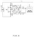
- FIG. 2 shows an electric current path that is assumed in the battery cell voltage equalization circuit 1 shown in FIG. 1 .
- the three electric current paths K1 through K3 shown in FIG. 2 are assumed in accordance with statues of the circuit.
- the electric current path K1 starts from the positive electrode of the battery cell B1 and reaches the negative electrode of the battery cell B1 via the fuse h1, the switch S1 the inductor L, and the fuse h2.
- This electric current path K1 is formed when the switch S1 has been controlled to an ON state and the switch S2 has been controlled to an OFF state. Note that when the battery cell B1 is discharged, an electric current flows in a clockwise direction through the electric current path K1 in FIG. 2 while when the battery cell B1 is charged, an electric current flows in a counterclockwise direction through the electric current path K1 in FIG. 2 .
- the electric current path K2 starts from the positive electrode of the battery cell B2 and reaches the negative electrode of the battery cell B2 via the fuse h2, the inductor L, the switch S2, and the fuse h3.
- This electric current path K2 is formed when the switch S1 has been controlled to an OFF state and the switch S2 has been controlled to an ON state. Note that when the battery cell B2 is discharged, an electric current flows in a clockwise direction through the electric current path K2 in FIG. 2 while when the battery cell B2 is charged, an electric current flows in a counterclockwise direction through the electric current path K2 in FIG. 2 .
- the electric current path K3 starts from the positive electrode of the battery cell B1 and reaches the negative electrode of the battery cell B2 via the fuse h1, the switch S1 the switch S2, and the fuse h3.
- This electric current path K3 is formed when both of the switches S1 and S2 are in an ON state (or in a shortcircuit state). In other words, the electric current path K3 is formed mainly when a failure has occurred in the battery cell voltage equalization circuit 1.
- the fuse h1 or h2 When an overcurrent has occurred in the electric current path K1, the fuse h1 or h2 will blow. Thereby, the battery cell B1 and the switch S1 are protected from the overcurrent. Also, when an overcurrent has occurred in the electric current path K2, the fuse h2 or h3 will blow. Thereby, the battery cell B2 and the switch S2 are protected from the overcurrent. Further, when an overcurrent has occurred in the electric current path K3, the fuse h1 or h3 will blow. Thereby, the battery cells B1 and B2 and the switches S1 and S2 are protected from the overcurrent.
- FIG. 1 and FIG. 2 fuses are provided to the respective wires that are electrically connected to the battery 100.
- the battery cell voltage equalization circuit 1 needs n+1 fuses.
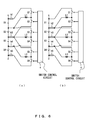
- FIG. 3 shows an example of a battery cell voltage equalization circuit having a smaller number of fuses than the number of those used in the configuration shown in FIG. 1 and FIG. 2 .
- the fuse h2 is not provided, unlike the configuration shown in FIG. 1 and FIG. 2 .
- the fuse h1 blows.
- the fuse h3 blows.
- the fuse h1 or h3 blows.
- the fuse h1 or h3 blows.
- the fuse h3 is not provided, unlike the configuration shown in FIG. 1 and FIG. 2 .
- the fuse h1 or h2 blows.
- the fuse h2 blows.
- the fuse h1 blows.
- the fuse h1 is not provided, unlike the configuration shown in FIG. 1 and FIG. 2 .
- the fuse h2 blows.
- the fuse h2 or h3 blows.
- the fuse h3 blows.
- the battery cell voltage equalization circuit 1 needs n fuses.
- the battery cell voltage equalization circuit 1 can equalize voltages of three or more battery cells.
- explanations will be given for a battery cell voltage equalization circuit that equalizes voltages of three or more battery cells.
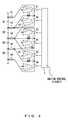
- FIG. 4 shows a configuration of a battery cell voltage equalization circuit that equalizes the voltages of four battery cells.
- the battery cell voltage equalization circuit includes switches S1 through S6, inductors L1 through L3, fuses h1 through h5, and a switch control circuit 4.
- the battery cells B1 through B4 are connected in series.
- the switches S1 and S2 and the inductor L1 are provided to the battery cells B1 and B2.
- the switches S1 and S2 and the inductor L1 have a circuit configuration equivalent to that of the switches S1 and S2 and the inductor L shown in FIG. 1 .
- the first terminal of the switch S1 is electrically connected to the positive electrode of the battery cell B1.
- the second terminal of the switch S1 is electrically connected to the first terminal of the switch S2 and is electrically connected to the negative electrode of the battery cell B1 via the inductor L1.
- the negative electrode of the battery cell B1 is electrically connected to the positive electrode of the battery cell B2.
- the second terminal of the switch S2 is electrically connected to the negative electrode of the battery cell B2.
- the switches S3 and S4 and the inductor L2 are provided to the battery cells B2 and B3.
- the first terminal of the switch S3 is electrically connected to the positive electrode of the battery cell B2.
- the second terminal of the switch S3 is electrically connected to the first terminal of the switch S4 and is electrically connected to the negative electrode of the battery cell B2 via the inductor L2.
- the negative electrode of the battery cell B2 is electrically connected to the positive electrode of the battery cell B3.
- the second terminal of the switch S4 is electrically connected to the negative electrode of the battery cell B3.
- the switches S5 and S6 and the inductor L3 are provided to the battery cells B3 and B4.
- the first terminal of the switch S5 is electrically connected to the positive electrode of the battery cell B3.
- the second terminal of the switch S5 is electrically connected to the first terminal of the switch S6 and is electrically connected to the negative electrode of the battery cell B3 via the inductor L3.
- the negative electrode of the battery cell B3 is electrically connected to the positive electrode of the battery cell B4.
- the second terminal of the switch S6 is electrically connected to the negative electrode of the battery cell B4.
- the battery cell voltage equalization circuit shown in FIG. 4 includes fuses h1 through h5 on respective wires that are electrically connected to the battery cells B1 through B4.
- the switch control circuit 4 controls the switches S1 through S6 so as to equalize the voltages of the battery cells B1 through B4. For this controlling, the switch control circuit 4 gives control signals that correspond to the respective control terminals of the switches S1 through S6. Specifically, when the switch control circuit 4 equalizes the voltages of the battery cells B1 and B2, it alternately controls the switches S1 and S2 to an ON state, when the switch control circuit 4 equalizes the voltages of the battery cells B2 and B3, it alternately controls the switches S3 and S4 to an ON state, and when the switch control circuit 4 equalizes the voltages of the battery cells B3 and B4, it alternately controls the switches S5 and S6 to an ON state.
- the equalization of the voltages of the battery cells B1 and B2, the equalization of the voltages of the battery cells B2 and B3, and the equalization of the voltages of the battery cells B3 and B4 are performed in for example a time-split method. Also, the switch control circuit 4 executes the above switching operation until the difference between the battery cells B1 through B4 (for example, the difference between the maximum value and the minimum value) becomes smaller than a prescribed threshold.
- the electric current paths K1 through K9 shown in FIG. 4 are assumed.
- the electric current paths K1 through K3 are substantially the same as the electric current paths K1 through K3 shown in FIG. 2 .
- the electric current paths K4 through K6 and the electric current paths K7 through K9 have roughly the same path patterns as those of the electric current paths K1 through K3.
- the electric current paths K4 through K6 are formed in the equalization of the voltages of the battery cells B2 and B3 while the electric current paths K7 through K9 are formed in the equalization of the voltages of the battery cells B3 and B4.
- the fuse h1 or h2 blows.
- the fuse h2 or h3 blows.
- the fuse h1 or h3 blows.
- the fuse h1 or h3 blows.
- the fuse h2 or h3 blows.
- the fuse h3 or h4 blows.
- the fuse h2 or h4 blows.
- the fuse h3 or h4 blows.
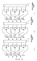
- FIG. 5 and FIG. 6 show examples of battery cell voltage equalization circuits having a smaller number of fuses than the number of those used in the configuration shown in FIG. 4 .
- the fuse h5 is not provided, unlike the configuration shown in FIG. 4 .
- the respective fuses h4, h3, h2 and h1 are not provided, unlike the configuration shown in FIG. 4 .
- one of the fuses blows so as to protect the battery cells B1 through B4 and the switches S1 through S6 from the overcurrent.
- FIG. 7 explains a configuration and a method for detecting a fuse blowout in the battery cell voltage equalization circuit 1.
- the battery cell voltage equalization circuit 1 includes voltage sensors 5-1 and 5-2 and a current sensor 6 for detecting a fuse blowout in addition to the constituents shown in FIG. 1 .
- the voltage sensor 5-1 detects the voltage between both ends of the switch S1.
- the voltage sensor 5-2 detects the voltage between both ends of the switch S2.
- the current sensor 6 includes a shunt resistor provided in the inductor L in series so as to detect an electric current flowing through the inductor L.
- the determination of a fuse blowout is performed by the battery controller 2 shown in FIG. 1 .
- the battery controller 2 monitors the voltage E1 of the battery cell B1 detected by the voltage sensor 3-1, the voltage E2 of the battery cell B2 detected by the voltage sensor 3-2, the voltage V1 between both ends of the switch S1 detected by the voltage sensor 5-1, the voltage V2 between both ends of the switch S2 detected by the voltage sensor 5-2, and an inductor current detected by the current sensor 6.
- the battery controller 2 can determine the state of the fuse h1 by monitoring outputs of the voltage sensor 5-1.
- the battery controller 2 controls both of the switches S1 and S2 to an OFF state.
- V2 is nearly equal to E2.
- the battery controller 2 can determine the state of the fuse h2 by monitoring outputs from the voltage sensors 3-2 and 5-2.
- the state determination of the fuse h3 is roughly the same as the method of determining the state of the fuse h1. However, the battery controller 2 monitors an output from the voltage sensor 5-2 so as to determine the state of the fuse h3.
Landscapes
- Engineering & Computer Science (AREA)
- Power Engineering (AREA)
- Manufacturing & Machinery (AREA)
- Chemical & Material Sciences (AREA)
- Chemical Kinetics & Catalysis (AREA)
- Electrochemistry (AREA)
- General Chemical & Material Sciences (AREA)
- Charge And Discharge Circuits For Batteries Or The Like (AREA)
- Secondary Cells (AREA)
Applications Claiming Priority (2)
| Application Number | Priority Date | Filing Date | Title |
|---|---|---|---|
| JP2012012818A JP5387703B2 (ja) | 2012-01-25 | 2012-01-25 | 電池セル電圧均等化回路 |
| PCT/JP2012/078221 WO2013111410A1 (fr) | 2012-01-25 | 2012-10-31 | Circuit d'égalisation de tension de cellule de batterie |
Publications (2)
| Publication Number | Publication Date |
|---|---|
| EP2808973A1 true EP2808973A1 (fr) | 2014-12-03 |
| EP2808973A4 EP2808973A4 (fr) | 2015-11-11 |
Family
ID=48873152
Family Applications (1)
| Application Number | Title | Priority Date | Filing Date |
|---|---|---|---|
| EP12866674.0A Withdrawn EP2808973A4 (fr) | 2012-01-25 | 2012-10-31 | Circuit d'égalisation de tension de cellule de batterie |
Country Status (5)
| Country | Link |
|---|---|
| US (1) | US20150022155A1 (fr) |
| EP (1) | EP2808973A4 (fr) |
| JP (1) | JP5387703B2 (fr) |
| CN (1) | CN104040826A (fr) |
| WO (1) | WO2013111410A1 (fr) |
Cited By (1)
| Publication number | Priority date | Publication date | Assignee | Title |
|---|---|---|---|---|
| CN104485703A (zh) * | 2014-12-04 | 2015-04-01 | 中国科学院广州能源研究所 | 一种锂离子储能电池电压均衡方法及其电路 |
Families Citing this family (8)
| Publication number | Priority date | Publication date | Assignee | Title |
|---|---|---|---|---|
| JP2012191679A (ja) * | 2011-03-08 | 2012-10-04 | Dendo Sharyo Gijutsu Kaihatsu Kk | バランス補正装置および蓄電システム |
| WO2013097070A1 (fr) * | 2011-12-26 | 2013-07-04 | 易速达休闲育乐股份有限公司 | Appareil pour connexion parallèle et protection des batteries d'un véhicule électrique |
| WO2017033398A1 (fr) * | 2015-08-27 | 2017-03-02 | パナソニックIpマネジメント株式会社 | Dispositif de gestion et dispositif de stockage d'énergie |
| CN106877279B (zh) * | 2016-01-25 | 2019-05-17 | 法拉第未来公司 | 用于电动车辆的冗余电路断开的方法及系统、具有冗余电池保护的车辆 |
| CN110832334B (zh) * | 2017-06-20 | 2022-09-27 | 株式会社杰士汤浅国际 | 故障诊断装置 |
| JP7007681B2 (ja) * | 2017-09-29 | 2022-01-25 | NExT-e Solutions株式会社 | 制御装置、バランス補正システム、蓄電システム、及び、装置 |
| TWI726687B (zh) * | 2020-04-16 | 2021-05-01 | 財團法人工業技術研究院 | 電池系統、電壓平衡程序之控制方法與平衡電量之計算方法 |
| US20240383421A1 (en) * | 2023-05-19 | 2024-11-21 | Bauer Energy Solution, Llc | Integrated energy storage device |
Family Cites Families (18)
| Publication number | Priority date | Publication date | Assignee | Title |
|---|---|---|---|---|
| DE3940929C1 (fr) * | 1989-12-12 | 1991-05-08 | Fraunhofer-Gesellschaft Zur Foerderung Der Angewandten Forschung Ev, 8000 Muenchen, De | |
| JPH06311752A (ja) * | 1993-04-22 | 1994-11-04 | Fuji Electric Co Ltd | 三相多重式逆変換器 |
| JP3328656B2 (ja) * | 1994-05-25 | 2002-09-30 | 株式会社岡村研究所 | 電池の充電制御装置及び方法 |
| US5742150A (en) * | 1996-09-16 | 1998-04-21 | Khuwatsamrit; Thakoengdet | Power supply and method of protecting batteries therein |
| JP2000016200A (ja) * | 1998-07-03 | 2000-01-18 | Hitachi Ltd | 車両用電源制御装置 |
| JP4006877B2 (ja) * | 1999-03-30 | 2007-11-14 | 株式会社デンソー | 組電池の電圧調整装置及び組電池の電圧調整方法 |
| US6150795A (en) * | 1999-11-05 | 2000-11-21 | Power Designers, Llc | Modular battery charge equalizers and method of control |
| JP2001157367A (ja) * | 1999-11-24 | 2001-06-08 | Taiyo Yuden Co Ltd | 組み電池セルの接続不良検出方法及び電源装置 |
| JP4378009B2 (ja) * | 1999-12-28 | 2009-12-02 | Fdk株式会社 | 直列接続された2次電池のバランス補正方法および装置 |
| JP2005143160A (ja) | 2003-11-04 | 2005-06-02 | Toshiba Corp | 二次電池パック及び二次電池システム |
| JP2007283974A (ja) * | 2006-04-19 | 2007-11-01 | Auto Network Gijutsu Kenkyusho:Kk | 車両用電源システム |
| JP4319205B2 (ja) | 2006-06-14 | 2009-08-26 | 株式会社Nttファシリティーズ | 電池管理装置及び電池管理方法 |
| US7633400B2 (en) * | 2006-11-20 | 2009-12-15 | Adc Telecommunications, Inc. | Fuse and breaker alarm device and method using a finite state machine |
| JP5279261B2 (ja) * | 2007-12-27 | 2013-09-04 | 三洋電機株式会社 | 充電状態均等化装置及びこれを具えた組電池システム |
| JP5188370B2 (ja) * | 2008-11-21 | 2013-04-24 | 三洋電機株式会社 | バッテリシステム |
| JP2010220377A (ja) | 2009-03-17 | 2010-09-30 | Panasonic Corp | 蓄電装置 |
| JP2010257775A (ja) | 2009-04-24 | 2010-11-11 | Sanyo Electric Co Ltd | バッテリモジュール、バッテリシステムおよび電動車両 |
| CN201902973U (zh) * | 2010-11-26 | 2011-07-20 | 杭州大来机械有限公司 | 一种设有电池均衡系统的太阳能道钉 |
-
2012
- 2012-01-25 JP JP2012012818A patent/JP5387703B2/ja not_active Expired - Fee Related
- 2012-10-31 WO PCT/JP2012/078221 patent/WO2013111410A1/fr not_active Ceased
- 2012-10-31 US US14/372,301 patent/US20150022155A1/en not_active Abandoned
- 2012-10-31 CN CN201280067335.4A patent/CN104040826A/zh active Pending
- 2012-10-31 EP EP12866674.0A patent/EP2808973A4/fr not_active Withdrawn
Cited By (1)
| Publication number | Priority date | Publication date | Assignee | Title |
|---|---|---|---|---|
| CN104485703A (zh) * | 2014-12-04 | 2015-04-01 | 中国科学院广州能源研究所 | 一种锂离子储能电池电压均衡方法及其电路 |
Also Published As
| Publication number | Publication date |
|---|---|
| CN104040826A (zh) | 2014-09-10 |
| WO2013111410A1 (fr) | 2013-08-01 |
| JP2013153588A (ja) | 2013-08-08 |
| JP5387703B2 (ja) | 2014-01-15 |
| EP2808973A4 (fr) | 2015-11-11 |
| US20150022155A1 (en) | 2015-01-22 |
Similar Documents
| Publication | Publication Date | Title |
|---|---|---|
| EP2808973A1 (fr) | Circuit d'égalisation de tension de cellule de batterie | |
| JP5624907B2 (ja) | 蓄電装置、断線検知装置、車両及び断線検知方法 | |
| JP5789846B2 (ja) | 車両用の電源装置とこの電源装置を備える車両 | |
| US9520613B2 (en) | Battery control with block selection | |
| JP5708625B2 (ja) | 蓄電システム | |
| JP6172176B2 (ja) | 電池監視装置 | |
| JP6111848B2 (ja) | 蓄電システム | |
| US9178367B2 (en) | Balance correction apparatus and electric storage system | |
| JP4707638B2 (ja) | 車両用の電源装置 | |
| JP5709601B2 (ja) | 蓄電装置および蓄電装置の電圧均等化方法 | |
| JP6643923B2 (ja) | 電池システムの電池パック交換方法及び電池パック | |
| CN103023090B (zh) | 半导体电路、电池监视系统、控制程序以及控制方法 | |
| CN104917223A (zh) | 电池监视装置 | |
| JP2012016174A (ja) | 車両用の電源装置 | |
| CN107870284B (zh) | 电压检测装置 | |
| JP5900431B2 (ja) | 電池監視装置、及び、電池ユニット | |
| WO2017043236A1 (fr) | Dispositif de contrôle de batterie de stockage | |
| WO2016063760A1 (fr) | Dispositif d'alimentation électrique, dispositif de protection et procédé de protection | |
| JP5168330B2 (ja) | 負荷駆動装置およびそれを備える車両ならびに負荷駆動装置の制御方法 | |
| JP2014090635A (ja) | 蓄電システム | |
| JP6787705B2 (ja) | 異常検出装置、および組電池システム | |
| JP6137470B2 (ja) | 電源制御装置 | |
| CN106936175A (zh) | 充放电控制电路及电池装置 | |
| JP5533010B2 (ja) | 電池電圧監視装置 | |
| JP6499455B2 (ja) | 監視装置、及び電池監視システム |
Legal Events
| Date | Code | Title | Description |
|---|---|---|---|
| PUAI | Public reference made under article 153(3) epc to a published international application that has entered the european phase |
Free format text: ORIGINAL CODE: 0009012 |
|
| 17P | Request for examination filed |
Effective date: 20140708 |
|
| AK | Designated contracting states |
Kind code of ref document: A1 Designated state(s): AL AT BE BG CH CY CZ DE DK EE ES FI FR GB GR HR HU IE IS IT LI LT LU LV MC MK MT NL NO PL PT RO RS SE SI SK SM TR |
|
| DAX | Request for extension of the european patent (deleted) | ||
| RA4 | Supplementary search report drawn up and despatched (corrected) |
Effective date: 20151008 |
|
| RIC1 | Information provided on ipc code assigned before grant |
Ipc: H02J 7/00 20060101AFI20151002BHEP Ipc: H01M 10/44 20060101ALI20151002BHEP Ipc: H01M 10/48 20060101ALI20151002BHEP Ipc: H02J 7/02 20060101ALI20151002BHEP |
|
| STAA | Information on the status of an ep patent application or granted ep patent |
Free format text: STATUS: THE APPLICATION IS DEEMED TO BE WITHDRAWN |
|
| 18D | Application deemed to be withdrawn |
Effective date: 20160507 |