EP2808976A1 - Agencement de circuit pour la partie primaire d'un système de transmission d'énergie sans contact, et élément de transmission - Google Patents
Agencement de circuit pour la partie primaire d'un système de transmission d'énergie sans contact, et élément de transmission Download PDFInfo
- Publication number
- EP2808976A1 EP2808976A1 EP13169729.4A EP13169729A EP2808976A1 EP 2808976 A1 EP2808976 A1 EP 2808976A1 EP 13169729 A EP13169729 A EP 13169729A EP 2808976 A1 EP2808976 A1 EP 2808976A1
- Authority
- EP
- European Patent Office
- Prior art keywords
- converter
- switching
- circuit arrangement
- resonant
- input
- Prior art date
- Legal status (The legal status is an assumption and is not a legal conclusion. Google has not performed a legal analysis and makes no representation as to the accuracy of the status listed.)
- Withdrawn
Links
Images
Classifications
-
- B—PERFORMING OPERATIONS; TRANSPORTING
- B60—VEHICLES IN GENERAL
- B60L—PROPULSION OF ELECTRICALLY-PROPELLED VEHICLES; SUPPLYING ELECTRIC POWER FOR AUXILIARY EQUIPMENT OF ELECTRICALLY-PROPELLED VEHICLES; ELECTRODYNAMIC BRAKE SYSTEMS FOR VEHICLES IN GENERAL; MAGNETIC SUSPENSION OR LEVITATION FOR VEHICLES; MONITORING OPERATING VARIABLES OF ELECTRICALLY-PROPELLED VEHICLES; ELECTRIC SAFETY DEVICES FOR ELECTRICALLY-PROPELLED VEHICLES
- B60L53/00—Methods of charging batteries, specially adapted for electric vehicles; Charging stations or on-board charging equipment therefor; Exchange of energy storage elements in electric vehicles
- B60L53/10—Methods of charging batteries, specially adapted for electric vehicles; Charging stations or on-board charging equipment therefor; Exchange of energy storage elements in electric vehicles characterised by the energy transfer between the charging station and the vehicle
- B60L53/12—Inductive energy transfer
- B60L53/126—Methods for pairing a vehicle and a charging station, e.g. establishing a one-to-one relation between a wireless power transmitter and a wireless power receiver
-
- B—PERFORMING OPERATIONS; TRANSPORTING
- B60—VEHICLES IN GENERAL
- B60L—PROPULSION OF ELECTRICALLY-PROPELLED VEHICLES; SUPPLYING ELECTRIC POWER FOR AUXILIARY EQUIPMENT OF ELECTRICALLY-PROPELLED VEHICLES; ELECTRODYNAMIC BRAKE SYSTEMS FOR VEHICLES IN GENERAL; MAGNETIC SUSPENSION OR LEVITATION FOR VEHICLES; MONITORING OPERATING VARIABLES OF ELECTRICALLY-PROPELLED VEHICLES; ELECTRIC SAFETY DEVICES FOR ELECTRICALLY-PROPELLED VEHICLES
- B60L53/00—Methods of charging batteries, specially adapted for electric vehicles; Charging stations or on-board charging equipment therefor; Exchange of energy storage elements in electric vehicles
- B60L53/10—Methods of charging batteries, specially adapted for electric vehicles; Charging stations or on-board charging equipment therefor; Exchange of energy storage elements in electric vehicles characterised by the energy transfer between the charging station and the vehicle
- B60L53/12—Inductive energy transfer
-
- H—ELECTRICITY
- H02—GENERATION; CONVERSION OR DISTRIBUTION OF ELECTRIC POWER
- H02J—ELECTRIC POWER NETWORKS; CIRCUIT ARRANGEMENTS OR SYSTEMS FOR SUPPLYING OR DISTRIBUTING ELECTRIC POWER; SYSTEMS FOR STORING ELECTRIC ENERGY
- H02J50/00—Circuit arrangements or systems for wireless supply or distribution of electric power
- H02J50/10—Circuit arrangements or systems for wireless supply or distribution of electric power using inductive coupling
- H02J50/12—Circuit arrangements or systems for wireless supply or distribution of electric power using inductive coupling of the resonant type
-
- H—ELECTRICITY
- H02—GENERATION; CONVERSION OR DISTRIBUTION OF ELECTRIC POWER
- H02J—ELECTRIC POWER NETWORKS; CIRCUIT ARRANGEMENTS OR SYSTEMS FOR SUPPLYING OR DISTRIBUTING ELECTRIC POWER; SYSTEMS FOR STORING ELECTRIC ENERGY
- H02J7/00—Circuit arrangements for charging or discharging batteries or for supplying loads from batteries
- H02J7/02—Circuit arrangements for charging or discharging batteries or for supplying loads from batteries for charging batteries from AC mains by converters
-
- B—PERFORMING OPERATIONS; TRANSPORTING
- B60—VEHICLES IN GENERAL
- B60L—PROPULSION OF ELECTRICALLY-PROPELLED VEHICLES; SUPPLYING ELECTRIC POWER FOR AUXILIARY EQUIPMENT OF ELECTRICALLY-PROPELLED VEHICLES; ELECTRODYNAMIC BRAKE SYSTEMS FOR VEHICLES IN GENERAL; MAGNETIC SUSPENSION OR LEVITATION FOR VEHICLES; MONITORING OPERATING VARIABLES OF ELECTRICALLY-PROPELLED VEHICLES; ELECTRIC SAFETY DEVICES FOR ELECTRICALLY-PROPELLED VEHICLES
- B60L2210/00—Converter types
- B60L2210/40—DC to AC converters
-
- H—ELECTRICITY
- H02—GENERATION; CONVERSION OR DISTRIBUTION OF ELECTRIC POWER
- H02J—ELECTRIC POWER NETWORKS; CIRCUIT ARRANGEMENTS OR SYSTEMS FOR SUPPLYING OR DISTRIBUTING ELECTRIC POWER; SYSTEMS FOR STORING ELECTRIC ENERGY
- H02J2105/00—Networks for supplying or distributing electric power characterised by their spatial reach or by the load
- H02J2105/30—Networks for supplying or distributing electric power characterised by their spatial reach or by the load the load networks being external to vehicles, i.e. exchanging power with vehicles
- H02J2105/33—Networks for supplying or distributing electric power characterised by their spatial reach or by the load the load networks being external to vehicles, i.e. exchanging power with vehicles exchanging power with road vehicles
- H02J2105/37—Networks for supplying or distributing electric power characterised by their spatial reach or by the load the load networks being external to vehicles, i.e. exchanging power with vehicles exchanging power with road vehicles exchanging power with electric vehicles [EV] or with hybrid electric vehicles [HEV]
-
- H—ELECTRICITY
- H02—GENERATION; CONVERSION OR DISTRIBUTION OF ELECTRIC POWER
- H02J—ELECTRIC POWER NETWORKS; CIRCUIT ARRANGEMENTS OR SYSTEMS FOR SUPPLYING OR DISTRIBUTING ELECTRIC POWER; SYSTEMS FOR STORING ELECTRIC ENERGY
- H02J2207/00—Details of circuit arrangements for charging or discharging batteries or supplying loads from batteries
- H02J2207/20—Charging or discharging characterised by the power electronics converter
-
- H—ELECTRICITY
- H02—GENERATION; CONVERSION OR DISTRIBUTION OF ELECTRIC POWER
- H02J—ELECTRIC POWER NETWORKS; CIRCUIT ARRANGEMENTS OR SYSTEMS FOR SUPPLYING OR DISTRIBUTING ELECTRIC POWER; SYSTEMS FOR STORING ELECTRIC ENERGY
- H02J50/00—Circuit arrangements or systems for wireless supply or distribution of electric power
- H02J50/005—Mechanical details of housing or structure aiming to accommodate the power transfer means, e.g. mechanical integration of coils, antennas or transducers into emitting or receiving devices
-
- Y—GENERAL TAGGING OF NEW TECHNOLOGICAL DEVELOPMENTS; GENERAL TAGGING OF CROSS-SECTIONAL TECHNOLOGIES SPANNING OVER SEVERAL SECTIONS OF THE IPC; TECHNICAL SUBJECTS COVERED BY FORMER USPC CROSS-REFERENCE ART COLLECTIONS [XRACs] AND DIGESTS
- Y02—TECHNOLOGIES OR APPLICATIONS FOR MITIGATION OR ADAPTATION AGAINST CLIMATE CHANGE
- Y02T—CLIMATE CHANGE MITIGATION TECHNOLOGIES RELATED TO TRANSPORTATION
- Y02T10/00—Road transport of goods or passengers
- Y02T10/60—Other road transportation technologies with climate change mitigation effect
- Y02T10/70—Energy storage systems for electromobility, e.g. batteries
-
- Y—GENERAL TAGGING OF NEW TECHNOLOGICAL DEVELOPMENTS; GENERAL TAGGING OF CROSS-SECTIONAL TECHNOLOGIES SPANNING OVER SEVERAL SECTIONS OF THE IPC; TECHNICAL SUBJECTS COVERED BY FORMER USPC CROSS-REFERENCE ART COLLECTIONS [XRACs] AND DIGESTS
- Y02—TECHNOLOGIES OR APPLICATIONS FOR MITIGATION OR ADAPTATION AGAINST CLIMATE CHANGE
- Y02T—CLIMATE CHANGE MITIGATION TECHNOLOGIES RELATED TO TRANSPORTATION
- Y02T10/00—Road transport of goods or passengers
- Y02T10/60—Other road transportation technologies with climate change mitigation effect
- Y02T10/7072—Electromobility specific charging systems or methods for batteries, ultracapacitors, supercapacitors or double-layer capacitors
-
- Y—GENERAL TAGGING OF NEW TECHNOLOGICAL DEVELOPMENTS; GENERAL TAGGING OF CROSS-SECTIONAL TECHNOLOGIES SPANNING OVER SEVERAL SECTIONS OF THE IPC; TECHNICAL SUBJECTS COVERED BY FORMER USPC CROSS-REFERENCE ART COLLECTIONS [XRACs] AND DIGESTS
- Y02—TECHNOLOGIES OR APPLICATIONS FOR MITIGATION OR ADAPTATION AGAINST CLIMATE CHANGE
- Y02T—CLIMATE CHANGE MITIGATION TECHNOLOGIES RELATED TO TRANSPORTATION
- Y02T10/00—Road transport of goods or passengers
- Y02T10/60—Other road transportation technologies with climate change mitigation effect
- Y02T10/72—Electric energy management in electromobility
-
- Y—GENERAL TAGGING OF NEW TECHNOLOGICAL DEVELOPMENTS; GENERAL TAGGING OF CROSS-SECTIONAL TECHNOLOGIES SPANNING OVER SEVERAL SECTIONS OF THE IPC; TECHNICAL SUBJECTS COVERED BY FORMER USPC CROSS-REFERENCE ART COLLECTIONS [XRACs] AND DIGESTS
- Y02—TECHNOLOGIES OR APPLICATIONS FOR MITIGATION OR ADAPTATION AGAINST CLIMATE CHANGE
- Y02T—CLIMATE CHANGE MITIGATION TECHNOLOGIES RELATED TO TRANSPORTATION
- Y02T90/00—Enabling technologies or technologies with a potential or indirect contribution to GHG emissions mitigation
- Y02T90/10—Technologies relating to charging of electric vehicles
- Y02T90/14—Plug-in electric vehicles
Definitions
- the invention relates to a circuit arrangement for the primary part of a system for contactless energy transmission, according to the preamble of claim 1, and a Matter talklement as a primary part for a system for contactless energy transfer to a secondary part, according to the preamble of claim. 6
- an electronic device in particular a transformer head for supplying the drive of an at least partially electrically operated vehicle based on inductive energy transmission.
- This device has a housing with a secondary winding and an integrated rectifier inside.
- the primary side which is fed from the grid and provides the energy for the operation and / or charging of the energy store on the secondary side, is typically constructed as an arrangement of several separate units due to many different assemblies.
- the primary side must also have one or more of the modules input filter, protection circuit, rectifier, power factor correction filter, up-converter, then typically DC / DC down converter, resonant DC / AC converter, high-frequency lines and at least one primary coil.
- a typical design provides an electronics with fans for wall mounting, from which high frequency cables go to other electronics on or in the floor, which then the primary coil of the under the car or in the floor, in the ground, in a roadway or the like. fed.
- the primary part In the primary part, the regulation of the energy to be transmitted is to be realized.
- the primary part typically comprises a voltage regulation device.
- Object of the present invention is thus to achieve the highest possible integration for the primary part of a system for contactless energy transfer and simplify this primary part for this purpose circuitry and construction.
- the entrainment in the vehicle for connection to conventional power sources at any location should be possible.
- a circuit arrangement for the primary part of a system for contactless energy transmission at least a power supply, a rectifier, a step-up converter, preferably with power factor correction filter, a resonant DC / AC converter and outputs to at least one primary coil, optionally also an input filter and a protection circuit between power supply and rectifier.
- this arrangement for achieving the object is characterized in that each input of the resonant DC / AC converter is followed by a respective controllable switching arrangement, wherein each input of the converter is connected to continuously switched switching arrangement with a capacitor and a first output of the converter and wherein each input of the converter is connected to a switched capacitor switching arrangement with a capacitance and a second output of the converter.
- This novel structure eliminates the voltage regulation by, for example, a DC / DC buck converter, since the transmitted power at constant voltage can be regulated by changing the excitation of the resonant converter by means of the switching arrangements.
- the resonant DC / AC converter can be connected directly downstream of the boost converter and be supplied by this with DC voltage.
- the switching arrangements are connected to a control electronics, in which a sequence for driving the switching arrangements is implemented to switch alternately one of the switching arrangements continuously and to turn off the other switching arrangement blocked.
- control electronics a sequence for driving the switching arrangements is implemented, the switching continuously switching circuit for a switching cycle, preferably for equal shares of the cycle time, in particular each switching arrangement substantially half the cycle time.
- control of the switching elements takes place in such a way that they are switched on and off in the zero crossing of the current in order to minimize the losses. Under certain circumstances, this results in a switching frequency, which deviates from the resonant frequency, but this is quite desirable.
- This design of the control electronics results in optimal utilization of the energy supplied with simple control option.
- a reduction of the power to half can be achieved in a simple manner by an output of the converter permanently connected by an appropriate control of the switch arrangements with an input of the converter and only the other output alternately connected to one or the other input of the converter.
- a sequence for driving the switching arrangements is implemented, which varies the cycle time in response to the power to be transmitted in integer steps, in such a way that the resonant circuit oscillates with the harmonic of the switching frequency of the converter.
- the switching can be done with one-third or one-fifth of the resonance frequency, corresponding to only one-third or one-fifth of the frequency is transmitted, thus reducing the power to one third or one fifth of the original value.
- a transformer element is also suitable as a primary part for a system for contactless energy transmission to a secondary part, which comprises a circuit arrangement according to at least one of the preceding paragraphs, which is accommodated in a common housing.
- This includes at least one power supply and the control electronics for the primary coil.
- each primary coil is housed in the common housing for even greater integration and enhanced portability to use the primary in any location that needs only one power source.
- At least one heat-conducting element preferably copper or aluminum plates, connects the housing to at least one of the components arranged therein, cooling of the primary part sufficient for the charging cycle can be ensured by contact of the housing with a cool surface.
- the cool surface may be, for example, the ground below an electric vehicle to be charged.
- the plates may be equipped with hollow channels in which a medium circulates for heat transport, preferably air or water.
- An advantageous transmitter element is characterized in that the circuit arrangement arranged in the housing is provided with a connection for a conventional power supply.
- the primary part can be operated on any conventional power source, which offers the highest possible flexibility for the operation of the primary part.
- a transmitter element may be characterized in that the interior of the housing has a potting compound which surrounds the components contained therein.
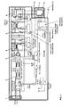
- Fig. 1 shows the modules of a primary part, as it finds application in a system for contactless energy transfer, for example.
- Such systems are used, for example, for contactless charging of the traction batteries of electric vehicles, where the energy for charging the battery through the primary coil of the primary part is transmitted to the secondary coil according to the principle of a transformer and converted there into a charging current for the battery.
- the primary part which must also provide for the regulation of the transmitted energy, typically and as in Fig. 1 recognizable a network connection 1, an input filter and a protection circuit, preferably realized by a common assembly 2, a rectifier 3, a power factor correction filter 4, possibly a boost converter, a DC / DC down converter 5, a resonant DC / AC converter 6, and at least a primary coil 7.
- a network connection typically and as in Fig. 1 recognizable a network connection 1, an input filter and a protection circuit, preferably realized by a common assembly 2, a rectifier 3, a power factor correction filter 4, possibly a boost converter, a DC / DC down converter 5, a resonant DC / AC converter 6, and at least a primary coil 7.
- Conventional systems distribute these modules on several, at least two, units 8, 9, which are connected to each other via energy and / or data lines. From the resonant DC / AC converter 6 to the primary coil 7 even expensive and sensitive high-frequency lines 10 must be provided.
- the unit combined in a first housing 8 usually comprises at least the mains connection 1 and the associated electronics 2, i. at least one input filter and the protection circuit, as well as fans.
- the unit 8 is usually designed for wall mounting.
- additional electronics are integrated with the first housing 8, such as the rectifier 3, power factor correction filter 4, if any, the boost converter, the DC / DC buck converter 5, and the DC / AC resonant converter 6.
- a power factor correction filter 4 is an electrical or electronic circuit which increases the so-called power factor so that it remains within a legal range.
- first housing 8 From the first housing 8 lead high-frequency lines 10 to a second housing 9, which comprises at least one primary coil 7.
- This second housing 9 is typically placed below an electric vehicle to be charged, lying on the floor of a garage or charging station, embedded in the ground below a parking space of the vehicle, od. Like.
- the DC / DC buck converter in Fig. 1 denoted by the reference numeral 5
- exposed expensive high-frequency lines in Fig. 1 marked with 10
- At least one heat-conducting element can dissipate the heat generated therein to the outside, for example to the ground or the surrounding air.
- Heat-conducting elements may preferably be copper or aluminum plates, which connect the housing 11 with at least one of the components arranged therein.
- these are preferably equipped with hollow channels in which a medium for heat transport, such as air or water circulates.
- a transformer element according to the invention can also be operated directly at any conventional power source as the primary part of a contactless charging system due to the high degree of integration. For this purpose, only a corresponding connection of the housing 11 arranged in the circuit arrangement is provided.
- the interior of the housing 11 may be filled with a potting compound which surrounds the components contained therein to substantially improve heat transfer and dielectric strength as well as mechanical strength and resistance to mechanical stresses.
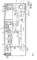
- each input of the resonant DC / AC converter 6 is followed by a respective controllable switching arrangement 12, each with a common control unit 13, optionally including a self-oscillating driver 14, is actuated.
- This combination of circuit arrangements 12 and the arrangement of control unit 13 and driver 14 allows influencing the excitation of the resonant DC / AC converter 6, which determines the transmitted power.
- a voltage control by, for example, a DC / DC down converter can thus be avoided, so that the resonant DC / AC converter 6 can be connected directly downstream of the boost converter 4 and can be supplied with DC voltage from it.
- control electronics comprising at least the control unit 13 and the self-oscillating driver 14, a sequence for driving the switching devices 12 is advantageously implemented according to which alternately one of the switching devices 12 is switched continuously and the other switching device 12 is switched off.
- the control unit 13 together with the driver 14 provides a sequence for driving the switching arrangements 12, in which for a switching cycle successively both switching arrangements 12 are switched continuously, preferably for equal shares of the cycle time.
- each of the two switching arrangement 12 is switched open or fired for substantially half the cycle time.
- the control of the switching elements of the switching assemblies 12 is such that they are switched on and off at the zero crossing of the current, which minimizes the losses. It may also happen that the switching frequency, which differs from the resonant frequency of the resonant converter 6, but this is quite desirable to make optimal use of the energy fed in despite simple control.
- an output of the converter 6 is permanently connected to an input of the converter 6 and only the other output is alternately connected to one or the other input of the converter 6.
- the cycle time can also be varied in integer steps depending on the power to be transmitted, in which case the resonant circuit oscillates with the harmonic of the switching frequency of the converter 6.
- the switching can be done with one third or one fifth of the resonant frequency of the transducer 6, and accordingly only one third or one fifth of the power is transmitted from the primary part to the secondary part.
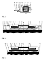
- the common housing 11 of the primary part is shaped in the form of a substantially cuboidal, preferably rectangular and thin in one dimension relative to the other dimensions thin plate.
- the housing 11 is thermally and preferably also mechanically connected to the floor 12, could also be embedded in the floor 12.
- the housing 11 is closed on all sides or at least closable and consists of a good heat-conducting, preferably metallic material such as aluminum. It is provided with an internally mounted and structured metal plate 13, in which cooling channels 14 are formed, in which a coolant, preferably air, in a closed circuit - symbolized by the arrows designated 15 - circulates. This circuit 15 is supported or driven by the fan 16.
- electronic assemblies 2 to 6 are arranged, for example, rectifier 3, boost converter, power factor correction filter 4, DC / DC down converter 5, inverter and resonant DC / AC converter 6, which draw their energy via a power cord 17 with power plug 18 directly from the AC power and their waste heat to the metal plate 13.
- This waste heat is absorbed by the cooling air in the circuit 15 and discharged at flow through the cooling channels 14 to the bottom 12 (symbolized by the arrows 19).
- the housing 11 has on its in use position the secondary part facing side, in the illustrated case of lying on the floor 12 or mounted plate above, an opening which is air-tight and waterproof covered by a non-metallic plate 20.
- a non-metallic plate 20 Under this plate 20 is the arrangement for contactless transmission of energy to the secondary part, consisting preferably of the primary coil 7 and preferably a ferrite screen 21 and a resonant capacitor 22, which is electrically and thermally isolated by an insulating plate 23 of the metallic plate 13 to In particular, to cope with the high resonance voltages occurring and to prevent a backflow of heat upwards.
- This arrangement with the resonant circuit is cooled by the exhaust air circulating in the housing 11 of the electronic assemblies.
Landscapes
- Engineering & Computer Science (AREA)
- Power Engineering (AREA)
- Computer Networks & Wireless Communication (AREA)
- Transportation (AREA)
- Mechanical Engineering (AREA)
- Dc-Dc Converters (AREA)
- Electric Propulsion And Braking For Vehicles (AREA)
Priority Applications (3)
| Application Number | Priority Date | Filing Date | Title |
|---|---|---|---|
| EP13169729.4A EP2808976A1 (fr) | 2013-05-29 | 2013-05-29 | Agencement de circuit pour la partie primaire d'un système de transmission d'énergie sans contact, et élément de transmission |
| EP14728347.7A EP3005526B1 (fr) | 2013-05-29 | 2014-05-23 | Agencement de circuit pour la partie primaire d'un système de transmission d'énergie sans contact, et élément de transmission |
| PCT/IB2014/061652 WO2014199255A1 (fr) | 2013-05-29 | 2014-05-23 | Circuit pour la partie primaire d'un système de transmission d'énergie sans contact, et élément de transmission |
Applications Claiming Priority (1)
| Application Number | Priority Date | Filing Date | Title |
|---|---|---|---|
| EP13169729.4A EP2808976A1 (fr) | 2013-05-29 | 2013-05-29 | Agencement de circuit pour la partie primaire d'un système de transmission d'énergie sans contact, et élément de transmission |
Publications (1)
| Publication Number | Publication Date |
|---|---|
| EP2808976A1 true EP2808976A1 (fr) | 2014-12-03 |
Family
ID=48520786
Family Applications (2)
| Application Number | Title | Priority Date | Filing Date |
|---|---|---|---|
| EP13169729.4A Withdrawn EP2808976A1 (fr) | 2013-05-29 | 2013-05-29 | Agencement de circuit pour la partie primaire d'un système de transmission d'énergie sans contact, et élément de transmission |
| EP14728347.7A Active EP3005526B1 (fr) | 2013-05-29 | 2014-05-23 | Agencement de circuit pour la partie primaire d'un système de transmission d'énergie sans contact, et élément de transmission |
Family Applications After (1)
| Application Number | Title | Priority Date | Filing Date |
|---|---|---|---|
| EP14728347.7A Active EP3005526B1 (fr) | 2013-05-29 | 2014-05-23 | Agencement de circuit pour la partie primaire d'un système de transmission d'énergie sans contact, et élément de transmission |
Country Status (2)
| Country | Link |
|---|---|
| EP (2) | EP2808976A1 (fr) |
| WO (1) | WO2014199255A1 (fr) |
Cited By (6)
| Publication number | Priority date | Publication date | Assignee | Title |
|---|---|---|---|---|
| WO2019170838A1 (fr) * | 2018-03-08 | 2019-09-12 | Mahle International Gmbh | Dispositif de charge par induction |
| WO2021175887A1 (fr) * | 2020-03-05 | 2021-09-10 | Mahle International Gmbh | Dispositif de charge à induction stationnaire pour transfert d'énergie sans fil |
| DE102020212388A1 (de) | 2020-09-30 | 2022-03-31 | Mahle International Gmbh | Bodenbaugruppe für eine induktive Ladevorrichtung |
| DE102020215074A1 (de) | 2020-11-30 | 2022-06-02 | Mahle International Gmbh | Elektromagnetische Induktionsladeeinrichtung |
| US11981222B2 (en) | 2021-04-09 | 2024-05-14 | Mahle International Gmbh | System with stationary inductive charging device |
| DE102023134357A1 (de) * | 2023-12-07 | 2025-06-12 | Brusa Elektronik Ag | Hauptspulenbaugruppe und modul mit einer hauptspulenbaugruppe |
Families Citing this family (3)
| Publication number | Priority date | Publication date | Assignee | Title |
|---|---|---|---|---|
| DE102017207266A1 (de) | 2017-04-28 | 2018-10-31 | Mahle International Gmbh | Induktionsladevorrichtung |
| DE102022213357A1 (de) * | 2022-12-09 | 2024-06-20 | Mahle International Gmbh | Stationäre Induktionsladevorrichtung sowie induktives Fahrzeugladesystem mit derselben |
| DE102024100964A1 (de) * | 2024-01-12 | 2025-07-17 | Mahle International Gmbh | Bodenbaugruppe und Fahrzeugladesystem |
Citations (4)
| Publication number | Priority date | Publication date | Assignee | Title |
|---|---|---|---|---|
| US6160374A (en) * | 1999-08-02 | 2000-12-12 | General Motors Corporation | Power-factor-corrected single-stage inductive charger |
| US20110254377A1 (en) * | 2010-04-08 | 2011-10-20 | Qualcomm Incorporated | Wireless power transmission in electric vehicles |
| WO2011151038A1 (fr) * | 2010-06-02 | 2011-12-08 | Friwo Gerätebau Gmbh | Montage pour un système de transfert d'énergie par induction, sans contact |
| WO2013017200A2 (fr) | 2011-08-02 | 2013-02-07 | Sew-Eurodrive Gmbh & Co. Kg | Appareil électronique, en particulier tête de transmission, et système de transfert d'énergie sans contact |
Family Cites Families (1)
| Publication number | Priority date | Publication date | Assignee | Title |
|---|---|---|---|---|
| FR2750267B1 (fr) | 1996-06-19 | 1998-09-18 | Peugeot | Dispositif pour recharger les batteries d'accumulateurs d'un vehicule electrique |
-
2013
- 2013-05-29 EP EP13169729.4A patent/EP2808976A1/fr not_active Withdrawn
-
2014
- 2014-05-23 WO PCT/IB2014/061652 patent/WO2014199255A1/fr not_active Ceased
- 2014-05-23 EP EP14728347.7A patent/EP3005526B1/fr active Active
Patent Citations (4)
| Publication number | Priority date | Publication date | Assignee | Title |
|---|---|---|---|---|
| US6160374A (en) * | 1999-08-02 | 2000-12-12 | General Motors Corporation | Power-factor-corrected single-stage inductive charger |
| US20110254377A1 (en) * | 2010-04-08 | 2011-10-20 | Qualcomm Incorporated | Wireless power transmission in electric vehicles |
| WO2011151038A1 (fr) * | 2010-06-02 | 2011-12-08 | Friwo Gerätebau Gmbh | Montage pour un système de transfert d'énergie par induction, sans contact |
| WO2013017200A2 (fr) | 2011-08-02 | 2013-02-07 | Sew-Eurodrive Gmbh & Co. Kg | Appareil électronique, en particulier tête de transmission, et système de transfert d'énergie sans contact |
Non-Patent Citations (1)
| Title |
|---|
| CHING-MING LAI: "Study and implementation of a high power factor single-stage contactless power supply with load/gap detection mechanisms", POWER ELECTRONICS SYSTEMS AND APPLICATIONS (PESA), 2011 4TH INTERNATIONAL CONFERENCE ON, IEEE, 8 June 2011 (2011-06-08), pages 1 - 5, XP031925350, ISBN: 978-1-4577-0205-1, DOI: 10.1109/PESA.2011.5982896 * |
Cited By (11)
| Publication number | Priority date | Publication date | Assignee | Title |
|---|---|---|---|---|
| WO2019170838A1 (fr) * | 2018-03-08 | 2019-09-12 | Mahle International Gmbh | Dispositif de charge par induction |
| US11552502B2 (en) | 2018-03-08 | 2023-01-10 | Mahle International Gmbh | Induction charging device |
| WO2021175887A1 (fr) * | 2020-03-05 | 2021-09-10 | Mahle International Gmbh | Dispositif de charge à induction stationnaire pour transfert d'énergie sans fil |
| CN115427254A (zh) * | 2020-03-05 | 2022-12-02 | 马勒国际有限公司 | 用于无线能量传输的固定式感应充电装置 |
| CN115427254B (zh) * | 2020-03-05 | 2023-07-28 | 马勒国际有限公司 | 用于无线能量传输的固定式感应充电装置 |
| US11820245B2 (en) | 2020-03-05 | 2023-11-21 | Mahle International Gmbh | Stationary induction charging device for wireless energy transfer |
| DE102020212388A1 (de) | 2020-09-30 | 2022-03-31 | Mahle International Gmbh | Bodenbaugruppe für eine induktive Ladevorrichtung |
| US12095276B2 (en) | 2020-09-30 | 2024-09-17 | Mahle International Gmbh | Ground assembly for an inductive charging device |
| DE102020215074A1 (de) | 2020-11-30 | 2022-06-02 | Mahle International Gmbh | Elektromagnetische Induktionsladeeinrichtung |
| US11981222B2 (en) | 2021-04-09 | 2024-05-14 | Mahle International Gmbh | System with stationary inductive charging device |
| DE102023134357A1 (de) * | 2023-12-07 | 2025-06-12 | Brusa Elektronik Ag | Hauptspulenbaugruppe und modul mit einer hauptspulenbaugruppe |
Also Published As
| Publication number | Publication date |
|---|---|
| EP3005526A1 (fr) | 2016-04-13 |
| WO2014199255A1 (fr) | 2014-12-18 |
| EP3005526B1 (fr) | 2017-12-13 |
Similar Documents
| Publication | Publication Date | Title |
|---|---|---|
| EP3005526B1 (fr) | Agencement de circuit pour la partie primaire d'un système de transmission d'énergie sans contact, et élément de transmission | |
| DE112015001844B4 (de) | Ladevorrichtung für Elektrofahrzeuge | |
| EP3524463B1 (fr) | Unité électronique pour systèmes de charge inductives | |
| EP3428000A1 (fr) | Dispositif de chargement d'au moins une batterie | |
| EP2885853B1 (fr) | Dispositif accumulateur d'énergie connectable ainsi que procédé permettant de faire fonctionner un dispositif accumulateur d'énergie connectable | |
| WO2016037737A1 (fr) | Bobine de transfert d'énergie par induction | |
| DE102013217816A1 (de) | Vorrichtung zur induktiven Energieübertragung und Verfahren zum Betreiben einer Vorrichtung zur induktiven Energieübertragung | |
| DE112016003577T5 (de) | Ladegerät mit integriertem DC/DC-Wandler | |
| DE102009052680A1 (de) | Ladevorrichtung zum Laden einer Batterie eines Kraftfahrzeugs mit Tiefsetzsteller | |
| DE102018208358A1 (de) | Elektrisches Bordnetz, Fortbewegungsmittel und elektrische Schaltung zum Heizen einer Batterie | |
| DE102019204141A1 (de) | Fahrzeuginterner motorgetriebener kompressor | |
| DE112019003942T5 (de) | Drahtgebundenes/drahtloses integriertes Leistungsempfangssystem | |
| EP3065152A1 (fr) | Partie primaire d'un appareil de chargement inductif | |
| DE102018216236A1 (de) | Ladeschaltung für einen fahrzeugseitigen elektrischen Energiespeicher | |
| DE102018203263A1 (de) | Ladeeinrichtung für ein Kraftfahrzeug | |
| WO2020187996A1 (fr) | Convertisseur de réseau de bord | |
| WO2016055180A1 (fr) | Procédé et système de charge sans contact d'un objet fonctionnant sur batterie | |
| DE112006002319T5 (de) | Hochleistungs-, Starkstrom-Einrastverbinder mit integrierter EMI-Filterung | |
| DE102014201440A1 (de) | Kraftfahrzeugbordnetz mit optimierter Durchschaltfunktion | |
| DE102008009913A1 (de) | Stromrichtermodul der Leistungselektronik | |
| WO2015144619A1 (fr) | Circuit magnétique permettant la charge dynamique de véhicules électriques | |
| DE102013109223A1 (de) | Schaltnetzteilvorrichtung | |
| WO2010009971A1 (fr) | Convertisseur continu-continu cadencé polyphasé | |
| DE102018105608A1 (de) | Ladeanordnung für Kraftfahrzeuge mit Schaltungssteuerung auf der Empfängerseite | |
| DE4305605C2 (de) | Anordnung zur Anpassung einer gelieferten Netzspannung an eine gewünschte Verbraucherspannung |
Legal Events
| Date | Code | Title | Description |
|---|---|---|---|
| PUAI | Public reference made under article 153(3) epc to a published international application that has entered the european phase |
Free format text: ORIGINAL CODE: 0009012 |
|
| 17P | Request for examination filed |
Effective date: 20130529 |
|
| AK | Designated contracting states |
Kind code of ref document: A1 Designated state(s): AL AT BE BG CH CY CZ DE DK EE ES FI FR GB GR HR HU IE IS IT LI LT LU LV MC MK MT NL NO PL PT RO RS SE SI SK SM TR |
|
| AX | Request for extension of the european patent |
Extension state: BA ME |
|
| STAA | Information on the status of an ep patent application or granted ep patent |
Free format text: STATUS: THE APPLICATION IS DEEMED TO BE WITHDRAWN |
|
| 18D | Application deemed to be withdrawn |
Effective date: 20150604 |