EP2808982B1 - Rotierende elektrische maschine mit integrierter antriebsvorrichtung - Google Patents
Rotierende elektrische maschine mit integrierter antriebsvorrichtung Download PDFInfo
- Publication number
- EP2808982B1 EP2808982B1 EP12866453.9A EP12866453A EP2808982B1 EP 2808982 B1 EP2808982 B1 EP 2808982B1 EP 12866453 A EP12866453 A EP 12866453A EP 2808982 B1 EP2808982 B1 EP 2808982B1
- Authority
- EP
- European Patent Office
- Prior art keywords
- electric machine
- rotary electric
- inverter
- driving
- integral
- Prior art date
- Legal status (The legal status is an assumption and is not a legal conclusion. Google has not performed a legal analysis and makes no representation as to the accuracy of the status listed.)
- Active
Links
Images

Classifications
-
- H—ELECTRICITY
- H02—GENERATION; CONVERSION OR DISTRIBUTION OF ELECTRIC POWER
- H02K—DYNAMO-ELECTRIC MACHINES
- H02K9/00—Arrangements for cooling or ventilating
- H02K9/22—Arrangements for cooling or ventilating by solid heat conducting material embedded in, or arranged in contact with, the stator or rotor, e.g. heat bridges
- H02K9/227—Heat sinks
-
- H—ELECTRICITY
- H02—GENERATION; CONVERSION OR DISTRIBUTION OF ELECTRIC POWER
- H02K—DYNAMO-ELECTRIC MACHINES
- H02K5/00—Casings; Enclosures; Supports
- H02K5/04—Casings or enclosures characterised by the shape, form or construction thereof
-
- H—ELECTRICITY
- H02—GENERATION; CONVERSION OR DISTRIBUTION OF ELECTRIC POWER
- H02K—DYNAMO-ELECTRIC MACHINES
- H02K11/00—Structural association of dynamo-electric machines with electric components or with devices for shielding, monitoring or protection
- H02K11/04—Structural association of dynamo-electric machines with electric components or with devices for shielding, monitoring or protection for rectification
- H02K11/049—Rectifiers associated with stationary parts, e.g. stator cores
- H02K11/05—Rectifiers associated with casings, enclosures or brackets
-
- H—ELECTRICITY
- H02—GENERATION; CONVERSION OR DISTRIBUTION OF ELECTRIC POWER
- H02K—DYNAMO-ELECTRIC MACHINES
- H02K11/00—Structural association of dynamo-electric machines with electric components or with devices for shielding, monitoring or protection
- H02K11/30—Structural association with control circuits or drive circuits
- H02K11/33—Drive circuits, e.g. power electronics
-
- H—ELECTRICITY
- H02—GENERATION; CONVERSION OR DISTRIBUTION OF ELECTRIC POWER
- H02K—DYNAMO-ELECTRIC MACHINES
- H02K3/00—Details of windings
- H02K3/04—Windings characterised by the conductor shape, form or construction, e.g. with bar conductors
- H02K3/28—Layout of windings or of connections between windings
-
- H—ELECTRICITY
- H02—GENERATION; CONVERSION OR DISTRIBUTION OF ELECTRIC POWER
- H02M—APPARATUS FOR CONVERSION BETWEEN AC AND AC, BETWEEN AC AND DC, OR BETWEEN DC AND DC, AND FOR USE WITH MAINS OR SIMILAR POWER SUPPLY SYSTEMS; CONVERSION OF DC OR AC INPUT POWER INTO SURGE OUTPUT POWER; CONTROL OR REGULATION THEREOF
- H02M7/00—Conversion of AC power input into DC power output; Conversion of DC power input into AC power output
- H02M7/42—Conversion of DC power input into AC power output without possibility of reversal
- H02M7/44—Conversion of DC power input into AC power output without possibility of reversal by static converters
- H02M7/48—Conversion of DC power input into AC power output without possibility of reversal by static converters using discharge tubes with control electrode or semiconductor devices with control electrode
- H02M7/493—Conversion of DC power input into AC power output without possibility of reversal by static converters using discharge tubes with control electrode or semiconductor devices with control electrode the static converters being arranged for operation in parallel
Definitions
- the present invention relates to a driving-device-integral-type rotary electric machine in which a rotary electric machine and a driving device, which drives the electric rotary machine by supplying power, are integrally fixed.
- a pair of three-phase inverters is provided in a driving device, and the three-phase inverters are unevenly distributed around an axis of the rotary electric machine so as to be arranged (for example, refer to Patent Document 1).
- Patent Document 1 Japanese Patent Publication No. 4200885
- the present invention has been made to solve the above-described problems of the conventional driving-device-integral-type rotary electric machine, and an object of the invention is to provide a driving-device-integral-type rotary electric machine in which a current capacity for energizing the rotary electric machine is increased, and output power of the rotary electric machine can be increased.
- a driving-device-integral-type rotary electric machine of the present invention has the features of claim 1.
- the driving-device-integral-type rotary electric machine of the present invention heat radiation of the inverters is distributed, and a heat capacity of a heat sink, in which the inverters are mounted, is effectively utilized, whereby the driving-device-integral-type rotary electric machine, in which driving current is enhanced, and output power is improved, can be obtained.
- Fig. 1 is an axial-cross-sectional view illustrating a driving-device-coaxial-integral-type rotary electric machine according to Embodiment 1 of the present invention.
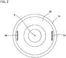
- Fig. 2 is a plane view illustrating a connecting portion of the rotary electric machine and a driving device in the driving-device-coaxial-integral-type rotary electric machine according to Embodiment 1 of the present invention.
- a rotary electric machine 2 of a driving-device-integral-type rotary electric machine 1 are formed as a brushless-type permanent magnet synchronous motor, and a first stator winding 5a and a second stator winding 5b, which are two pairs of three-phase stator windings, are wound around a stator core 3, which is formed by laminating electromagnetic steels, via an insulator 4 made from a resin.
- Each pair of the first stator winding 5a and the second stator winding 5b is formed as a delta connection by a winding terminal holder 7 installed in a terminal holder 6 made from a resin.
- first stator winding 5a and the second stator winding 5b may be formed as Y connections.
- stator windings may be formed as a pair of three-phase stator windings.
- two pairs of three-phase stator windings- the first stator winding 5a and the second stator winding 5b-are provided will be explained in the following description.
- the stator core 3 is inserted to a frame 10 made from aluminum so as to be composed of a stator 11 of the rotary electric machine 2.
- a bottom 101 is provided at one end portion (front-side end portion).
- An inside-low portion 102 for being fitted to a reduction mechanism (not illustrated) used as the other mechanism is provided at the bottom 101 of the frame 10 so as to be composed of an attachment portion 15 with respect to the reduction mechanism.
- a permanent magnet 17 for generating a field flux is attached to an outer circumference of a shaft 16 of the rotor 12.
- a boss 18 used as a coupling is attached to a front-side end portion of the shaft 16.
- the end portion of the frame 10 is opened, and an aperture of the frame 10 is linked to one end portion of a heat sink 19 of the driving device 8.
- the heat sink 19 is formed by using a die casting made from an aluminum alloy, and the other end portion is connected to a cover 23 of the driving device 8.
- a rear holder 20 is inserted to the aperture of the frame 10, and a rear bearing box 22 for installing a rear bearing 20, by which on end portion of the rotor 12 is supported, is formed at a central portion of the rear bearing 20.
- the first motor terminal 9a and the second motor terminal 9b are extended in an axis direction so as to be arranged at a position where the motor terminals are linearly symmetrical with respect to the extended axis X of the rotary electric machine 2, and those penetrate the rear bearing 20 as suitably indicated in Fig. 2 .
- the driving device 8 includes a microcomputer 24, a control board 26 made from glass epoxy, on which a first FET-driving circuit 25a and a second FET-driving circuit 25b are mounted, and two pairs of inverters 27a and 27b, on which power elements, such as a power MOSFET and the like, for three-phases are mounted.
- the inverter 27a is referred to as a first inverter
- the inverter 27b is referred to as a second inverter.
- a lead frame 28 is provided between the control board 26 and the first and second inverters 27a and 27b.
- the lead frame 28 is integrally formed in such a way that a terminal (not illustrated) made from copper, by which power is supplied to the first inverter 27a and second inverter 27b, and a terminal (not illustrated) made from copper, by which the first inverter 27a and second inverter 27b are connected to a capacitor (not illustrated) and a coil (not illustrated), are inserted to a resin. Moreover, a terminal (not illustrated) made from copper, by which a connector (not illustrated) is connected to the control board 26, the first inverter 27a, and second inverter 27b, is integrally inserted to the lead frame 28 so as to be formed.
- the first inverter 27a and the second inverter 27b are configured in such a way that the inverters are respectively contacted to a first protrusion 29a and a second protrusion 29b, which are formed on the heat sink 19, so as to be mounted, heat generated by the power element is transmitted to the heat sink 19.
- the first protrusion 29a and the second protrusion 29b are formed in such a way that the protrusions are extended in a direction where the axis X of the rotary electric machine 2 is extended.
- the first inverter 27a and the second inverter 27b are arranged at a position where the inverters are linearly symmetrical with respect to the axis X of the rotary electric machine 2.
- first inverter-signal terminal 30a and a second inverter-signal terminal 30b as well as a first inverter-motor terminal 31a and a second inverter-motor terminal 31b are respectively provided in the first inverter 27a and the second inverter 27b.
- the first inverter-signal terminal 30a and the second inverter-signal terminal 30b are connected to the control board 26, and the first inverter-motor terminal 31a and the second inverter-motor terminal 31b are connected to the first motor terminal 9a and the second motor terminal 9b, which penetrate the heat sink 19 so as to be protruded.
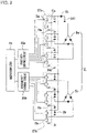
- Fig. 3 is a circuit diagram of the driving-device-coaxial-integral-type rotary electric machine according to Embodiment 1 of the present invention.
- the rotor 12 is the brushless-type permanent magnet synchronous motor as described above, and includes the first stator winding 5a and the second stator winding 5b, which are two pairs of three-phase stator windings formed as the delta connection.
- the first inverter 27a is composed of a first switching element Sa having six field-effect transistor (hereinafter, referred to as FET), three first shunt resistors Ra, and three first smoothing capacitors Ca.
- the second inverter 27b is composed of a second switching element Sb having six FET, three second shunt resistors Rb, and three second smoothing capacitors Cb.
- Positive-pole-side terminals of the first inverter 27a and the second inverter 27b are commonly connected, via a choke coil CL, to a positive-pole side of a battery BAT used as a DC power supply, and negative-pole-side terminals of the inverters are connected to ground level GND via the shunt resistors Ra and the shunt resistors Rb.
- AC-side output terminals of the first inverter 27a are connected to terminals of the first stator winding 5a so as to supply three-phase AC power to the first stator winding 5a
- AC-side output terminals of the second inverter 27b are connected to terminals of the second stator winding 5b so as to supply three-phase AC power to the second stator winding 5b.
- the first FET-driving circuit 25a controls a control signal, which is supplied to each gate of the first switching element Sa of the first inverter 27a, in accordance with a command outputted from the microcomputer 24 so as to drive the first inverter 27a.
- the second FET-driving circuit 25b controls a control signal, which is supplied to each gate of the second switching element Sb of the second inverter 27b, in accordance with a command outputted from the microcomputer 24 so as to drive the second inverter 27b.
- the rotor 12 of rotary electric machine 2 is rotated by energizing the first stator winding 5a and the second stator winding 5b or by energizing one of the stator windings.
- the first inverter 27a and the second inverter 27b are switched in accordance with a requirement so as to operate any of the inverters, whereby the stator winding can be driven, or the first inverter 27a and the second inverter 27b are concurrently operated, whereby the stator winding can be driven.
- the heat sink 19 is configured in such a way that heat capacities corresponding to volumes of portions, which are respectively corresponded to the first inverter 27a and the second inverter 27b and located immediately below the inverters, are roughly equivalent each other.
- thermal-transmission passages, by which heat is transmitted from the first inverter 27a and the second inverter 27b to the frame 10 via the portions of the heat sink 19, which are respectively located immediately below the inverters, are roughly equivalent each other. Therefore, heat generated from the first inverter 27a and the second inverter 27b is roughly and equivalently spread and radiated.
- the heat capacity of the heat sink 19 is roughly equal to the generated heat, which is permitted with respect to the heat capacity of the heat sink 19 and the radiation capacity toward the heat sink 19 and the frame 10, so that the power loss, which is generated when one of the inverters is singly operated, is equal to the power loss, which is generated when the both inverters are concurrently operated.
- the first inverter 27a and the second inverter 27b are concurrently operated, current, of which power loss is equivalent to a power loss at the time of operating one of the inverters, is passed through the both inverters.
- the thermal-transmission passages extended from the first inverter 27a and the second inverter 27b are roughly parallel to a direction where the axis X of the rotary electric machine 2 is extended, and lengths of the passages are short, whereby the radiation capability is improved. Furthermore, because the thermal-transmission passages are roughly parallel to a direction where the axis X of the rotary electric machine 2 is extended, the heat, which is generated by the first inverter 27a and the second inverter 27b and radiated to inside of the driving device 8, is reduced, whereby a temperature rise inside the driving device 8 can be suppressed.
- the rotary electric machine is configured in such a way that thermal-radiation surfaces of the first inverter 27a and the second inverter 27b and an installation surface of the heat sink 19 are vertical with respect to a direction where the axis X of the rotary electric machine 2 is extended, and the thermal-transmission passages are short, and the thermal-radiation capability is improved.
- the rotary electric machine is configured as described above, so that the heat, which is generated by the first inverter 27a and the second inverter 27b and radiated to inside of the driving device 8, can be reduced.
- the first stator winding 5a and the second stator winding 5b in which two pairs of three-phase windings are wound, are individually connected to the first inverter 27a and the second inverter 27b, and the individual circuits are configured. Therefore, an inter action is not operated between the two inverters, and an imbalance between the two inverters is suppressed, whereby the generated heat is uniformed.
- the first motor terminal 9a and the second motor terminal 9b which respectively correspond to the first stator winding 5a and the second stator winding 5, are arranged at a position where the motor terminals are linearly symmetrical with respect to the extended axis X of the rotary electric machine 2.
- a connecting portion for connecting the first stator winding 5a to the first inverter 27a and another connecting portion for connecting the second stator winding 5b to the second inverter 27b are arranged in a state where the connecting portions are linearly symmetrical with respect to a direction where the axis X of the rotary electric machine.
- the first motor terminal 9a and the second motor terminal 9b as well as the first stator winding 5a and the second stator winding 5 are arranged in a state where those are roughly and linearly symmetrical with each other in an electrical condition and a thermal condition, and the heat, which is generated from the first motor terminal 9a and the second motor terminal 9b, and from the first stator winding 5a and the second stator winding 5b, and from the first inverter 27a and the second inverter 27b, is radiated and spread, and then, the imbalance between the two inverters is suppressed, whereby the generated heat is uniformed.
- the first smoothing capacitors Ca and the second smoothing capacitors Cb which absorb ripple current passing through the first stator winding 5a and the second stator winding 5b of the rotary electric machine 2 are installed in the lead frame 28, and the capacitors are connected to the first inverter 27a and the second inverter 27b, which correspond to each other, via terminals (not illustrated).
- the choke coil CL which absorbs a noise, is also installed in the lead frame 28, and the choke coil CL is connected to a connector (not illustrated) via a terminal (not illustrated).
- a power connector and a signal connector are provided on the connector.
- each pair of three-phase inverters is installed in the heat sink in a state where the inverters are linearly symmetrical with respect to a shaft of the motor, and a heat capacity of the heat sink is roughly equivalent to a volume or a heat capacity of portions corresponding to each of inverters.
- the rotary electric machine is configured in such a way that a thermal-transmission passage for transmitting heat from the inverters to the heat sink is roughly equivalent to a thermal-transmission passage for transmitting heat from the heat sink to the frame, so that the radiation capacities of the inverters are roughly equivalent to etch other, and heat generated from the inverters is radiated and spread, and the imbalance between the two inverters is suppressed, whereby the generated heat is uniformed, whereby a temperature rise inside the driving device 8 can be suppressed.
- driving current is improved, and power of the rotary electric machine 2 is improved, and the device can be downsized.
- the attachment portion 15 for attaching the reduction mechanism or the like, the rotary electric machine 2, and the driving device 8 are sequentially and integrally configured in the same axis, so that heat generated from the driving device 8 is easily transmitted to the rotary electric machine 2, and thermal radiation capability of the driving device 8 is improved.
- driving current is improved, and power of the rotary electric machine 2 is improved, and the device can be downsized.
- the attachment portion 15, the rotary electric machine 2, and the driving device 8 are sequentially, coaxially, and integrally configured, whereas in a driving-device-coaxial-integral-type rotary electric machine according to Embodiment 2 of the present invention, an attachment portion 15, a driving device 8, and a rotary electric machine 2 are sequentially, coaxially, and integrally configured.
- the driving-device-coaxial-integral-type rotary electric machine according to Embodiment 1 or Embodiment 2 is applied to an electric power steering device.
- the rotary electric machine is used as a motor which generates assist torque for the electric power steering device.
- the driving-device-integral-type rotary electric machine of the present invention can be applied in every field, for example, in a field of an electric power steering system in a car, in which a rotary electric machine is used.
Landscapes
- Engineering & Computer Science (AREA)
- Power Engineering (AREA)
- Microelectronics & Electronic Packaging (AREA)
- Motor Or Generator Cooling System (AREA)
- Power Steering Mechanism (AREA)
Claims (9)
- Rotierende elektrische Maschine eines Typs mit integrierter Antriebseinrichtung, die Folgendes aufweist:eine rotierende elektrische Maschine (2) mit einem Statorkern (3), der in einen Rahmen (10) eingesetzt ist, undeine Antriebseinrichtung (8) zum Antreiben der rotierenden elektrischen Maschine (2) durch Zufuhr von Energie, die integral befestigt sind, wobeidie Antriebseinrichtung (8) einen ersten Wechselrichter (27a) und einen zweiten Wechselrichter (27b) aufweist, die ausgestaltet sind, um Statorwicklungen (5a, 5b) der rotierenden elektrischen Maschine (2) mit Energie zu versorgen, undder erste Wechselrichter (27a) und der zweite Wechselrichter (27b) auf einem Kühlkörper (19) in einem Zustand installiert und angeordnet sind, in dem die Wechselrichter (27a, 27b) in Bezug auf eine Achse der rotierenden elektrischen Maschine (2) in einer axialen Richtung linear symmetrisch sind, wobei der erste Wechselrichter (27a) und der zweite Wechselrichter (27b) mit einem ersten Vorsprung (29a) und einem zweiten Vorsprung (29b) in Kontakt stehen, die auf dem Kühlkörper (19) ausgebildet sind, undder Kühlkörper (19) so ausgestaltet ist, dass zumindest eine Wärmekapazität eines Abschnitts in Bezug auf den ersten Wechselrichter (27a) ungefähr gleich einer Wärmekapazität eines Abschnitts in Bezug auf den zweiten Wechselrichter (27b) ist, dadurch gekennzeichnet, dassder Kühlkörper (19) zwischen der Antriebseinrichtung (8) und der rotierenden elektrischen Maschine (2) angeordnet ist,eine Öffnung des Rahmens (10) mit einem Endabschnitt des Kühlkörpers (19) verbunden ist,wobei ein wärmeleitender Durchgang, der sich von dem ersten Wechselrichter (27a) durch den Kühlkörper (19) erstreckt, und ein wärmeleitender Durchgang, der sich von dem zweiten Wechselrichter (27b) durch den Kühlkörper (19) erstreckt, in der axialen Richtung linear symmetrisch in Bezug auf die Achse der rotierenden elektrischen Maschine (2) sind, und die wärmeleitenden Durchgänge ungefähr parallel zu einer Richtung sind, in der sich die Achse erstreckt,wobei ein hinterer Halter (20) in die Öffnung des Rahmens (10) eingesetzt ist, und ein hinterer Lagerkasten (22), der ein hinteres Lager (20) aufnimmt, durch das ein Endabschnitt des Rotors (12) gestützt wird, an einem zentralen Abschnitt des hinteren Lagers (20) ausgebildet ist, wobei der hintere Halter (20) zwischen dem Kühlkörper (19) und der rotierenden elektrischen Maschine (2) angeordnet ist.
- Rotierende elektrische Maschine eines Typs mit integrierter Antriebseinrichtung nach Anspruch 1, wobei, wenn der erste Wechselrichter (27a) und der zweite Wechselrichter (27b) so ausgestaltet sind, dass sie gleichzeitig betrieben werden, ein Strom an die beiden Wechselrichter (27a, 27b) angelegt wird, dessen Verlust gleich dem Verlust beim Betrieb nur eines der Wechselrichter (27a/27b) ist.
- Rotierende elektrische Maschine eines Typs mit integrierter Antriebseinrichtung nach Anspruch 2, wobei jeder Wert des an die beiden Wechselrichter (27a, 27b) angelegten Stroms das 1/√2-fache eines Wertes des Stroms beträgt, der nur an einen der Wechselrichter (27a/27b) angelegt wird.
- Rotierende elektrische Maschine eines Typs mit integrierter Antriebseinrichtung nach einem der Ansprüche 1 bis 3, wobei jede der Abstrahlungsflächen des ersten Wechselrichters (27a) und des zweiten Wechselrichters (27b) und eine Oberfläche eines Abschnitts des Kühlkörpers (19), auf dem jeder der Wechselrichter (27a, 27b) montiert ist, in einer vertikalen Richtung angeordnet sind, bezogen auf eine Richtung, in der sich die Achse der rotierenden elektrischen Maschine erstreckt.
- Rotierende elektrische Maschine eines Typs mit integrierter Antriebseinrichtung nach einem der Ansprüche 1 bis 4, wobei die Statorwicklungen aus einer ersten Statorwicklung (5a) und einer zweiten Statorwicklung (5b) bestehen, in einem Zustand, in dem die erste Statorwicklung (5a) mit dem ersten Wechselrichter (27a) verbunden ist und die zweite Statorwicklung (5b) mit dem zweiten Wechselrichter (27b) verbunden ist.
- Rotierende elektrische Maschine eines Typs mit integrierter Antriebseinrichtung nach einem der Ansprüche 1 bis 5, bei der ein Verbindungsabschnitt zum Verbinden der ersten Statorwicklung (5a) mit dem ersten Wechselrichter (27a) und ein weiterer Verbindungsabschnitt zum Verbinden der zweiten Statorwicklung (5b) mit dem zweiten Wechselrichter (27b) in einem Zustand angeordnet sind, in dem die Verbindungsabschnitte in Bezug auf die Achse der rotierenden elektrischen Maschine (2) linear symmetrisch sind.
- Rotierende elektrische Maschine eines Typs mit integrierter Antriebseinrichtung nach einem der Ansprüche 1 bis 6, die ferner einen Befestigungsabschnitt (15) aufweist, der an dem anderen Mechanismus befestigt ist, und der Befestigungsabschnitt (15), die rotierende elektrische Maschine (2) und die Antriebseinrichtung (8) in einem Zustand integral ausgestaltet sind, in dem der Befestigungsabschnitt (15), die rotierende elektrische Maschine (2) und die Antriebseinrichtung (8) aufeinanderfolgend angeordnet sind.
- Rotierende elektrische Maschine eines Typs mit integrierter Antriebseinrichtung nach einem der Ansprüche 1 bis 6, die ferner einen Befestigungsabschnitt (15) aufweist, der an dem anderen Mechanismus befestigt ist, und bei welcher der Befestigungsabschnitt (15), die rotierende elektrische Maschine (2) und die Antriebseinrichtung (8) in einem Zustand integral ausgestaltet sind, in dem der Befestigungsabschnitt (15), die Antriebseinrichtung (8) und die rotierende elektrische Maschine (2) aufeinanderfolgend angeordnet sind.
- Rotierende elektrische Maschine eines Typs mit integrierter Antriebseinrichtung nach einem der Ansprüche 1 bis 8, wobei die rotierende elektrische Maschine (2) ein Motor ist, der so ausgestaltet ist, dass er ein Hilfsdrehmoment für eine elektrische Servolenkungseinrichtung erzeugt.
Priority Applications (1)
| Application Number | Priority Date | Filing Date | Title |
|---|---|---|---|
| EP20173461.3A EP3713053B1 (de) | 2012-01-25 | 2012-01-25 | Rotierende elektrische maschine mit integrierter antriebsvorrichtung |
Applications Claiming Priority (1)
| Application Number | Priority Date | Filing Date | Title |
|---|---|---|---|
| PCT/JP2012/051490 WO2013111277A1 (ja) | 2012-01-25 | 2012-01-25 | 駆動装置一体型回転電機 |
Related Child Applications (2)
| Application Number | Title | Priority Date | Filing Date |
|---|---|---|---|
| EP20173461.3A Division EP3713053B1 (de) | 2012-01-25 | 2012-01-25 | Rotierende elektrische maschine mit integrierter antriebsvorrichtung |
| EP20173461.3A Division-Into EP3713053B1 (de) | 2012-01-25 | 2012-01-25 | Rotierende elektrische maschine mit integrierter antriebsvorrichtung |
Publications (3)
| Publication Number | Publication Date |
|---|---|
| EP2808982A1 EP2808982A1 (de) | 2014-12-03 |
| EP2808982A4 EP2808982A4 (de) | 2016-05-25 |
| EP2808982B1 true EP2808982B1 (de) | 2022-08-10 |
Family
ID=48873049
Family Applications (2)
| Application Number | Title | Priority Date | Filing Date |
|---|---|---|---|
| EP20173461.3A Active EP3713053B1 (de) | 2012-01-25 | 2012-01-25 | Rotierende elektrische maschine mit integrierter antriebsvorrichtung |
| EP12866453.9A Active EP2808982B1 (de) | 2012-01-25 | 2012-01-25 | Rotierende elektrische maschine mit integrierter antriebsvorrichtung |
Family Applications Before (1)
| Application Number | Title | Priority Date | Filing Date |
|---|---|---|---|
| EP20173461.3A Active EP3713053B1 (de) | 2012-01-25 | 2012-01-25 | Rotierende elektrische maschine mit integrierter antriebsvorrichtung |
Country Status (5)
| Country | Link |
|---|---|
| US (1) | US9570960B2 (de) |
| EP (2) | EP3713053B1 (de) |
| JP (1) | JP5752276B2 (de) |
| CN (1) | CN103931086B (de) |
| WO (1) | WO2013111277A1 (de) |
Families Citing this family (17)
| Publication number | Priority date | Publication date | Assignee | Title |
|---|---|---|---|---|
| EP3082245A4 (de) * | 2013-12-13 | 2017-03-22 | NSK Ltd. | Elektronische steuereinheit, elektrische servolenkung und fahrzeug |
| JP6582568B2 (ja) * | 2014-07-31 | 2019-10-02 | 株式会社デンソー | 駆動装置、および、これを用いた電動パワーステアリング装置 |
| JP2016034201A (ja) * | 2014-07-31 | 2016-03-10 | 株式会社デンソー | 駆動装置 |
| WO2016117114A1 (ja) * | 2015-01-23 | 2016-07-28 | 三菱電機株式会社 | 電動駆動装置 |
| JP2016140147A (ja) * | 2015-01-26 | 2016-08-04 | 株式会社デンソー | 回転電機 |
| US10793182B2 (en) * | 2015-02-18 | 2020-10-06 | Mitsubishi Electric Corporation | Integrated electric power steering apparatus |
| JP6457884B2 (ja) * | 2015-05-19 | 2019-01-23 | 株式会社日立製作所 | 車両用駆動装置 |
| US9954409B2 (en) * | 2015-07-27 | 2018-04-24 | Ford Global Technologies, Llc | Power supply device |
| JPWO2017022094A1 (ja) * | 2015-08-05 | 2017-10-19 | 三菱電機株式会社 | インバータ一体型モータ |
| EP3352362B1 (de) * | 2015-09-18 | 2022-02-23 | Mitsubishi Electric Corporation | Integrierte elektrische servolenkvorrichtung |
| JP6289530B2 (ja) * | 2016-04-14 | 2018-03-07 | 三菱電機株式会社 | 駆動装置一体型回転電機、及び、電動パワーステアリング装置 |
| JP6789000B2 (ja) * | 2016-05-16 | 2020-11-25 | Kyb株式会社 | 回転電機 |
| DE112017005928T5 (de) * | 2016-11-23 | 2019-08-01 | Nidec Corporation | Motor und elektrische Servolenkvorrichtung |
| CN107476951B (zh) * | 2017-08-08 | 2019-03-22 | 中山大洋电机股份有限公司 | 一体化电动空气压缩机及应用其的燃料电池空气进气系统 |
| JP6500285B1 (ja) | 2017-10-19 | 2019-04-17 | 本田技研工業株式会社 | 電力変換装置 |
| JP2020054149A (ja) * | 2018-09-27 | 2020-04-02 | 日本電産株式会社 | モータ |
| JP7428489B2 (ja) * | 2019-08-05 | 2024-02-06 | カヤバ株式会社 | 回転電機 |
Citations (1)
| Publication number | Priority date | Publication date | Assignee | Title |
|---|---|---|---|---|
| EP2371673A2 (de) * | 2010-03-31 | 2011-10-05 | Mitsubishi Electric Corporation | Elektrische Ansteuervorrichtung |
Family Cites Families (15)
| Publication number | Priority date | Publication date | Assignee | Title |
|---|---|---|---|---|
| JP4039288B2 (ja) * | 2003-03-25 | 2008-01-30 | 日産自動車株式会社 | 電力変換装置 |
| JP4291617B2 (ja) * | 2003-05-13 | 2009-07-08 | トヨタ自動車株式会社 | インバータ装置 |
| JP4200885B2 (ja) | 2003-11-21 | 2008-12-24 | 株式会社デンソー | 電動圧縮機用モータ駆動装置 |
| JP5435286B2 (ja) * | 2009-06-24 | 2014-03-05 | 株式会社デンソー | 駆動装置 |
| JP5624330B2 (ja) * | 2009-06-24 | 2014-11-12 | 株式会社デンソー | モータ |
| US20100277869A1 (en) * | 2009-09-24 | 2010-11-04 | General Electric Company | Systems, Methods, and Apparatus for Cooling a Power Conversion System |
| US8866353B2 (en) | 2010-01-29 | 2014-10-21 | Mitsubishi Electric Corporation | Inverter-integrated driving module |
| WO2011093202A1 (ja) * | 2010-01-29 | 2011-08-04 | 三菱電機株式会社 | インバータ一体型駆動モジュールおよびその製造方法 |
| JP5063722B2 (ja) * | 2010-03-19 | 2012-10-31 | 三菱電機株式会社 | 電動式駆動装置およびそれを搭載した電動式パワーステアリング装置 |
| JP5316469B2 (ja) * | 2010-04-16 | 2013-10-16 | 株式会社デンソー | 電動機の駆動装置及びこれを用いた電動装置 |
| KR20110116525A (ko) | 2010-04-19 | 2011-10-26 | 엘지전자 주식회사 | 3d 오브젝트를 제공하는 영상표시장치, 그 시스템 및 그 동작 제어방법 |
| JP5012953B2 (ja) | 2010-05-21 | 2012-08-29 | 株式会社デンソー | 駆動装置 |
| JP5170711B2 (ja) * | 2010-12-28 | 2013-03-27 | 株式会社デンソー | コントローラ |
| JP5969241B2 (ja) * | 2012-03-29 | 2016-08-17 | 株式会社デンソー | 駆動装置 |
| JP5807846B2 (ja) * | 2012-03-29 | 2015-11-10 | 株式会社デンソー | 駆動装置 |
-
2012
- 2012-01-25 WO PCT/JP2012/051490 patent/WO2013111277A1/ja not_active Ceased
- 2012-01-25 CN CN201280056097.7A patent/CN103931086B/zh active Active
- 2012-01-25 JP JP2013555040A patent/JP5752276B2/ja active Active
- 2012-01-25 EP EP20173461.3A patent/EP3713053B1/de active Active
- 2012-01-25 US US14/353,253 patent/US9570960B2/en active Active
- 2012-01-25 EP EP12866453.9A patent/EP2808982B1/de active Active
Patent Citations (1)
| Publication number | Priority date | Publication date | Assignee | Title |
|---|---|---|---|---|
| EP2371673A2 (de) * | 2010-03-31 | 2011-10-05 | Mitsubishi Electric Corporation | Elektrische Ansteuervorrichtung |
Also Published As
| Publication number | Publication date |
|---|---|
| EP2808982A1 (de) | 2014-12-03 |
| WO2013111277A1 (ja) | 2013-08-01 |
| US9570960B2 (en) | 2017-02-14 |
| EP3713053A1 (de) | 2020-09-23 |
| JPWO2013111277A1 (ja) | 2015-05-11 |
| EP3713053B1 (de) | 2022-11-23 |
| CN103931086B (zh) | 2017-06-23 |
| EP2808982A4 (de) | 2016-05-25 |
| US20150303776A1 (en) | 2015-10-22 |
| CN103931086A (zh) | 2014-07-16 |
| JP5752276B2 (ja) | 2015-07-22 |
Similar Documents
| Publication | Publication Date | Title |
|---|---|---|
| EP2808982B1 (de) | Rotierende elektrische maschine mit integrierter antriebsvorrichtung | |
| EP2840686B1 (de) | Elektrische drehmaschine | |
| US11509196B2 (en) | Motor vehicle and power converter device for a motor vehicle | |
| US9350228B2 (en) | Power conversion apparatus | |
| JP4144465B2 (ja) | 車両用インバータ一体型電動コンプレッサ | |
| US8188626B2 (en) | Controller-integrated electric rotating machine | |
| EP2141786B1 (de) | Rotierende elektrische Maschine für Fahrzeuge | |
| JP7847936B2 (ja) | インバータの第1部分からセットバックを形成する部分を備えるインバータ | |
| WO2015141272A1 (ja) | インバータ一体型電動圧縮機 | |
| WO2013164933A1 (ja) | インバータ装置 | |
| JP2013046447A (ja) | 電力変換装置 | |
| JP2006333587A (ja) | モータシステム | |
| US20220247249A1 (en) | Integrated electric drive with cooling device | |
| CN112260560A (zh) | 电力变换装置 | |
| JP5256892B2 (ja) | 車両用回転電機 | |
| WO2013065847A1 (ja) | インバータ装置 | |
| JP6934985B1 (ja) | 回転電機 | |
| JP2026013963A (ja) | 機電一体型電動機 | |
| JP2015171211A (ja) | 内燃機関用電動流体ポンプ |
Legal Events
| Date | Code | Title | Description |
|---|---|---|---|
| PUAI | Public reference made under article 153(3) epc to a published international application that has entered the european phase |
Free format text: ORIGINAL CODE: 0009012 |
|
| 17P | Request for examination filed |
Effective date: 20140505 |
|
| AK | Designated contracting states |
Kind code of ref document: A1 Designated state(s): AL AT BE BG CH CY CZ DE DK EE ES FI FR GB GR HR HU IE IS IT LI LT LU LV MC MK MT NL NO PL PT RO RS SE SI SK SM TR |
|
| DAX | Request for extension of the european patent (deleted) | ||
| RA4 | Supplementary search report drawn up and despatched (corrected) |
Effective date: 20160425 |
|
| RIC1 | Information provided on ipc code assigned before grant |
Ipc: H02K 11/33 20160101ALI20160419BHEP Ipc: H02M 7/48 20070101ALI20160419BHEP Ipc: H02K 11/00 20160101ALI20160419BHEP Ipc: H02K 5/18 20060101AFI20160419BHEP |
|
| STAA | Information on the status of an ep patent application or granted ep patent |
Free format text: STATUS: EXAMINATION IS IN PROGRESS |
|
| 17Q | First examination report despatched |
Effective date: 20200127 |
|
| GRAP | Despatch of communication of intention to grant a patent |
Free format text: ORIGINAL CODE: EPIDOSNIGR1 |
|
| STAA | Information on the status of an ep patent application or granted ep patent |
Free format text: STATUS: GRANT OF PATENT IS INTENDED |
|
| INTG | Intention to grant announced |
Effective date: 20220419 |
|
| GRAS | Grant fee paid |
Free format text: ORIGINAL CODE: EPIDOSNIGR3 |
|
| GRAA | (expected) grant |
Free format text: ORIGINAL CODE: 0009210 |
|
| STAA | Information on the status of an ep patent application or granted ep patent |
Free format text: STATUS: THE PATENT HAS BEEN GRANTED |
|
| AK | Designated contracting states |
Kind code of ref document: B1 Designated state(s): AL AT BE BG CH CY CZ DE DK EE ES FI FR GB GR HR HU IE IS IT LI LT LU LV MC MK MT NL NO PL PT RO RS SE SI SK SM TR |
|
| REG | Reference to a national code |
Ref country code: GB Ref legal event code: FG4D |
|
| REG | Reference to a national code |
Ref country code: AT Ref legal event code: REF Ref document number: 1511295 Country of ref document: AT Kind code of ref document: T Effective date: 20220815 Ref country code: CH Ref legal event code: EP |
|
| REG | Reference to a national code |
Ref country code: DE Ref legal event code: R096 Ref document number: 602012078601 Country of ref document: DE |
|
| REG | Reference to a national code |
Ref country code: IE Ref legal event code: FG4D |
|
| REG | Reference to a national code |
Ref country code: NL Ref legal event code: MP Effective date: 20220810 |
|
| REG | Reference to a national code |
Ref country code: LT Ref legal event code: MG9D |
|
| PG25 | Lapsed in a contracting state [announced via postgrant information from national office to epo] |
Ref country code: SE Free format text: LAPSE BECAUSE OF FAILURE TO SUBMIT A TRANSLATION OF THE DESCRIPTION OR TO PAY THE FEE WITHIN THE PRESCRIBED TIME-LIMIT Effective date: 20220810 Ref country code: RS Free format text: LAPSE BECAUSE OF FAILURE TO SUBMIT A TRANSLATION OF THE DESCRIPTION OR TO PAY THE FEE WITHIN THE PRESCRIBED TIME-LIMIT Effective date: 20220810 Ref country code: PT Free format text: LAPSE BECAUSE OF FAILURE TO SUBMIT A TRANSLATION OF THE DESCRIPTION OR TO PAY THE FEE WITHIN THE PRESCRIBED TIME-LIMIT Effective date: 20221212 Ref country code: NO Free format text: LAPSE BECAUSE OF FAILURE TO SUBMIT A TRANSLATION OF THE DESCRIPTION OR TO PAY THE FEE WITHIN THE PRESCRIBED TIME-LIMIT Effective date: 20221110 Ref country code: NL Free format text: LAPSE BECAUSE OF FAILURE TO SUBMIT A TRANSLATION OF THE DESCRIPTION OR TO PAY THE FEE WITHIN THE PRESCRIBED TIME-LIMIT Effective date: 20220810 Ref country code: LV Free format text: LAPSE BECAUSE OF FAILURE TO SUBMIT A TRANSLATION OF THE DESCRIPTION OR TO PAY THE FEE WITHIN THE PRESCRIBED TIME-LIMIT Effective date: 20220810 Ref country code: LT Free format text: LAPSE BECAUSE OF FAILURE TO SUBMIT A TRANSLATION OF THE DESCRIPTION OR TO PAY THE FEE WITHIN THE PRESCRIBED TIME-LIMIT Effective date: 20220810 Ref country code: FI Free format text: LAPSE BECAUSE OF FAILURE TO SUBMIT A TRANSLATION OF THE DESCRIPTION OR TO PAY THE FEE WITHIN THE PRESCRIBED TIME-LIMIT Effective date: 20220810 Ref country code: ES Free format text: LAPSE BECAUSE OF FAILURE TO SUBMIT A TRANSLATION OF THE DESCRIPTION OR TO PAY THE FEE WITHIN THE PRESCRIBED TIME-LIMIT Effective date: 20220810 |
|
| REG | Reference to a national code |
Ref country code: AT Ref legal event code: MK05 Ref document number: 1511295 Country of ref document: AT Kind code of ref document: T Effective date: 20220810 |
|
| PG25 | Lapsed in a contracting state [announced via postgrant information from national office to epo] |
Ref country code: PL Free format text: LAPSE BECAUSE OF FAILURE TO SUBMIT A TRANSLATION OF THE DESCRIPTION OR TO PAY THE FEE WITHIN THE PRESCRIBED TIME-LIMIT Effective date: 20220810 Ref country code: IS Free format text: LAPSE BECAUSE OF FAILURE TO SUBMIT A TRANSLATION OF THE DESCRIPTION OR TO PAY THE FEE WITHIN THE PRESCRIBED TIME-LIMIT Effective date: 20221210 Ref country code: HR Free format text: LAPSE BECAUSE OF FAILURE TO SUBMIT A TRANSLATION OF THE DESCRIPTION OR TO PAY THE FEE WITHIN THE PRESCRIBED TIME-LIMIT Effective date: 20220810 Ref country code: GR Free format text: LAPSE BECAUSE OF FAILURE TO SUBMIT A TRANSLATION OF THE DESCRIPTION OR TO PAY THE FEE WITHIN THE PRESCRIBED TIME-LIMIT Effective date: 20221111 |
|
| PG25 | Lapsed in a contracting state [announced via postgrant information from national office to epo] |
Ref country code: SM Free format text: LAPSE BECAUSE OF FAILURE TO SUBMIT A TRANSLATION OF THE DESCRIPTION OR TO PAY THE FEE WITHIN THE PRESCRIBED TIME-LIMIT Effective date: 20220810 Ref country code: RO Free format text: LAPSE BECAUSE OF FAILURE TO SUBMIT A TRANSLATION OF THE DESCRIPTION OR TO PAY THE FEE WITHIN THE PRESCRIBED TIME-LIMIT Effective date: 20220810 Ref country code: DK Free format text: LAPSE BECAUSE OF FAILURE TO SUBMIT A TRANSLATION OF THE DESCRIPTION OR TO PAY THE FEE WITHIN THE PRESCRIBED TIME-LIMIT Effective date: 20220810 Ref country code: CZ Free format text: LAPSE BECAUSE OF FAILURE TO SUBMIT A TRANSLATION OF THE DESCRIPTION OR TO PAY THE FEE WITHIN THE PRESCRIBED TIME-LIMIT Effective date: 20220810 Ref country code: AT Free format text: LAPSE BECAUSE OF FAILURE TO SUBMIT A TRANSLATION OF THE DESCRIPTION OR TO PAY THE FEE WITHIN THE PRESCRIBED TIME-LIMIT Effective date: 20220810 |
|
| REG | Reference to a national code |
Ref country code: DE Ref legal event code: R097 Ref document number: 602012078601 Country of ref document: DE |
|
| PG25 | Lapsed in a contracting state [announced via postgrant information from national office to epo] |
Ref country code: SK Free format text: LAPSE BECAUSE OF FAILURE TO SUBMIT A TRANSLATION OF THE DESCRIPTION OR TO PAY THE FEE WITHIN THE PRESCRIBED TIME-LIMIT Effective date: 20220810 Ref country code: EE Free format text: LAPSE BECAUSE OF FAILURE TO SUBMIT A TRANSLATION OF THE DESCRIPTION OR TO PAY THE FEE WITHIN THE PRESCRIBED TIME-LIMIT Effective date: 20220810 |
|
| PLBE | No opposition filed within time limit |
Free format text: ORIGINAL CODE: 0009261 |
|
| STAA | Information on the status of an ep patent application or granted ep patent |
Free format text: STATUS: NO OPPOSITION FILED WITHIN TIME LIMIT |
|
| P01 | Opt-out of the competence of the unified patent court (upc) registered |
Effective date: 20230512 |
|
| PG25 | Lapsed in a contracting state [announced via postgrant information from national office to epo] |
Ref country code: AL Free format text: LAPSE BECAUSE OF FAILURE TO SUBMIT A TRANSLATION OF THE DESCRIPTION OR TO PAY THE FEE WITHIN THE PRESCRIBED TIME-LIMIT Effective date: 20220810 |
|
| 26N | No opposition filed |
Effective date: 20230511 |
|
| PG25 | Lapsed in a contracting state [announced via postgrant information from national office to epo] |
Ref country code: SI Free format text: LAPSE BECAUSE OF FAILURE TO SUBMIT A TRANSLATION OF THE DESCRIPTION OR TO PAY THE FEE WITHIN THE PRESCRIBED TIME-LIMIT Effective date: 20220810 |
|
| REG | Reference to a national code |
Ref country code: CH Ref legal event code: PL |
|
| GBPC | Gb: european patent ceased through non-payment of renewal fee |
Effective date: 20230125 |
|
| PG25 | Lapsed in a contracting state [announced via postgrant information from national office to epo] |
Ref country code: LU Free format text: LAPSE BECAUSE OF NON-PAYMENT OF DUE FEES Effective date: 20230125 |
|
| REG | Reference to a national code |
Ref country code: BE Ref legal event code: MM Effective date: 20230131 |
|
| PG25 | Lapsed in a contracting state [announced via postgrant information from national office to epo] |
Ref country code: LI Free format text: LAPSE BECAUSE OF NON-PAYMENT OF DUE FEES Effective date: 20230131 Ref country code: GB Free format text: LAPSE BECAUSE OF NON-PAYMENT OF DUE FEES Effective date: 20230125 Ref country code: CH Free format text: LAPSE BECAUSE OF NON-PAYMENT OF DUE FEES Effective date: 20230131 |
|
| PG25 | Lapsed in a contracting state [announced via postgrant information from national office to epo] |
Ref country code: BE Free format text: LAPSE BECAUSE OF NON-PAYMENT OF DUE FEES Effective date: 20230131 |
|
| PG25 | Lapsed in a contracting state [announced via postgrant information from national office to epo] |
Ref country code: IE Free format text: LAPSE BECAUSE OF NON-PAYMENT OF DUE FEES Effective date: 20230125 |
|
| PG25 | Lapsed in a contracting state [announced via postgrant information from national office to epo] |
Ref country code: IT Free format text: LAPSE BECAUSE OF FAILURE TO SUBMIT A TRANSLATION OF THE DESCRIPTION OR TO PAY THE FEE WITHIN THE PRESCRIBED TIME-LIMIT Effective date: 20220810 |
|
| PG25 | Lapsed in a contracting state [announced via postgrant information from national office to epo] |
Ref country code: MC Free format text: LAPSE BECAUSE OF FAILURE TO SUBMIT A TRANSLATION OF THE DESCRIPTION OR TO PAY THE FEE WITHIN THE PRESCRIBED TIME-LIMIT Effective date: 20220810 |
|
| PG25 | Lapsed in a contracting state [announced via postgrant information from national office to epo] |
Ref country code: MC Free format text: LAPSE BECAUSE OF FAILURE TO SUBMIT A TRANSLATION OF THE DESCRIPTION OR TO PAY THE FEE WITHIN THE PRESCRIBED TIME-LIMIT Effective date: 20220810 |
|
| PG25 | Lapsed in a contracting state [announced via postgrant information from national office to epo] |
Ref country code: BG Free format text: LAPSE BECAUSE OF FAILURE TO SUBMIT A TRANSLATION OF THE DESCRIPTION OR TO PAY THE FEE WITHIN THE PRESCRIBED TIME-LIMIT Effective date: 20220810 |
|
| PG25 | Lapsed in a contracting state [announced via postgrant information from national office to epo] |
Ref country code: BG Free format text: LAPSE BECAUSE OF FAILURE TO SUBMIT A TRANSLATION OF THE DESCRIPTION OR TO PAY THE FEE WITHIN THE PRESCRIBED TIME-LIMIT Effective date: 20220810 |
|
| REG | Reference to a national code |
Ref country code: DE Ref legal event code: R081 Ref document number: 602012078601 Country of ref document: DE Owner name: MITSUBISHI ELECTRIC MOBILITY CORPORATION, JP Free format text: FORMER OWNER: MITSUBISHI ELECTRIC CORPORATION, TOKYO, JP |
|
| REG | Reference to a national code |
Ref country code: DE Ref legal event code: R084 Ref document number: 602012078601 Country of ref document: DE |
|
| PG25 | Lapsed in a contracting state [announced via postgrant information from national office to epo] |
Ref country code: CY Free format text: LAPSE BECAUSE OF FAILURE TO SUBMIT A TRANSLATION OF THE DESCRIPTION OR TO PAY THE FEE WITHIN THE PRESCRIBED TIME-LIMIT; INVALID AB INITIO Effective date: 20120125 |
|
| PG25 | Lapsed in a contracting state [announced via postgrant information from national office to epo] |
Ref country code: HU Free format text: LAPSE BECAUSE OF FAILURE TO SUBMIT A TRANSLATION OF THE DESCRIPTION OR TO PAY THE FEE WITHIN THE PRESCRIBED TIME-LIMIT; INVALID AB INITIO Effective date: 20120125 |
|
| PG25 | Lapsed in a contracting state [announced via postgrant information from national office to epo] |
Ref country code: TR Free format text: LAPSE BECAUSE OF FAILURE TO SUBMIT A TRANSLATION OF THE DESCRIPTION OR TO PAY THE FEE WITHIN THE PRESCRIBED TIME-LIMIT Effective date: 20220810 |
|
| PGFP | Annual fee paid to national office [announced via postgrant information from national office to epo] |
Ref country code: FR Payment date: 20251128 Year of fee payment: 15 |
|
| PGFP | Annual fee paid to national office [announced via postgrant information from national office to epo] |
Ref country code: DE Payment date: 20251203 Year of fee payment: 15 |