EP2809081A1 - Dispositif formant casque d'écoute - Google Patents
Dispositif formant casque d'écoute Download PDFInfo
- Publication number
- EP2809081A1 EP2809081A1 EP12861126.6A EP12861126A EP2809081A1 EP 2809081 A1 EP2809081 A1 EP 2809081A1 EP 12861126 A EP12861126 A EP 12861126A EP 2809081 A1 EP2809081 A1 EP 2809081A1
- Authority
- EP
- European Patent Office
- Prior art keywords
- headphone device
- ear
- housing
- nozzle section
- audio signal
- Prior art date
- Legal status (The legal status is an assumption and is not a legal conclusion. Google has not performed a legal analysis and makes no representation as to the accuracy of the status listed.)
- Ceased
Links
Images


Classifications
-
- H—ELECTRICITY
- H04—ELECTRIC COMMUNICATION TECHNIQUE
- H04R—LOUDSPEAKERS, MICROPHONES, GRAMOPHONE PICK-UPS OR LIKE ACOUSTIC ELECTROMECHANICAL TRANSDUCERS; ELECTRIC HEARING AIDS; PUBLIC ADDRESS SYSTEMS
- H04R1/00—Details of transducers, loudspeakers or microphones
- H04R1/10—Earpieces; Attachments therefor ; Earphones; Monophonic headphones
- H04R1/1058—Manufacture or assembly
-
- H—ELECTRICITY
- H04—ELECTRIC COMMUNICATION TECHNIQUE
- H04R—LOUDSPEAKERS, MICROPHONES, GRAMOPHONE PICK-UPS OR LIKE ACOUSTIC ELECTROMECHANICAL TRANSDUCERS; ELECTRIC HEARING AIDS; PUBLIC ADDRESS SYSTEMS
- H04R1/00—Details of transducers, loudspeakers or microphones
- H04R1/10—Earpieces; Attachments therefor ; Earphones; Monophonic headphones
- H04R1/1016—Earpieces of the intra-aural type
Definitions
- the present invention relates to a headphone device to be connected to a reproducing device through a cable, for outputting an audio signal output from the reproducing device.
- a headphone device including an ear pad to be inserted into an inside of an ear of a user, and electrically connected to a reproducing device through a cable, for outputting an audio signal output from the reproducing device.
- a protruding angle of the ear pad is offset by a given angle with respect to a housing, and thus the wearing comfort of the headphone device in the ear is enhanced (for example, see Patent Literature 1).
- FIG. 5 is a top view illustrating a state in which the related-art headphone device, in which the protruding angle of the ear pad is offset by a given angle with respect to the housing, is attached to the ear of the user.
- the upper side of the drawing sheet corresponds to an outer side of the ear of the user
- the right side of the drawing sheet corresponds to a front side of the user.
- a related-art headphone device 100 includes a housing 200 and an ear pad 4.
- the ear pad 4 is formed of an elastic body such as a resin/rubber member, and is arranged to be offset toward the front side of the user by a given angle with respect to the housing 200.
- the headphone device 100 inputs an audio signal output from a reproducing device (not shown) to a driver unit provided inside the housing 200, and the driver unit outputs the audio signal as a sound wave.
- the sound wave of the audio signal output by the driver unit is transmitted through the ear pad, and is emitted as sound to the inside of the ear of the user.
- a distal end of the ear pad 4 is inserted from an ear concha 501 toward an ear canal 502, and an outer peripheral portion of the ear pad 4 is held on an inner wall of an ear canal entrance 503.
- the ear canal entrance 503 of the ear 50 protrudes forward from an inner side of the ear concha 501.
- the ear pad 4 of the headphone device 100 is arranged to be offset toward the front side of the user with respect to the housing 200, and thus the outer peripheral portion of the ear pad 4 is properly held on the inner wall of the ear canal entrance 503. As a result, wearing comfort of the headphone device 100 is enhanced.
- the protruding angle of the ear pad is offset by a given angle with respect to the housing
- a part of an outer periphery of the housing 200 partially presses a swelling portion of the ear canal entrance 503 indicated by the arrow A in FIG. 5
- the housing 200 presses a swelling portion of a tragus 504 indicated by the arrow B in FIG. 5 .
- the ear canal entrance 503 and the tragus 504 are continuously pressed by the outer peripheral portion of the housing 200 for a long period of time, and hence a pain may be caused in the ear canal entrance 503 and the tragus 504.
- wearing comfort of the headphone device 100 may be deteriorated.
- a headphone device for outputting an audio signal input to an input terminal through a cable
- the headphone device including: a driver unit fixed to a housing, the driver unit including a diaphragm for emitting the audio signal as sound; and a nozzle section having one end fixed to the housing, another end holding an ear pad, and a hollow interior, the nozzle section being formed so as to be inclined by a predetermined angle with respect to the housing in a region from a portion of the nozzle section fixed to the housing toward a distal end portion of the nozzle section.
- the nozzle section in the headphone device, includes an outwardly curved portion formed at an intermediate portion of one side surface of the nozzle section so as to swell outwardly.
- the nozzle section in the headphone device, includes an inwardly curved portion formed at an intermediate portion of one side surface of the nozzle section so as to swell inwardly.
- the headphone device further includes a wing-like plate portion formed of a thin plate and arranged above the housing.
- the headphone device including the ear pad to be inserted into the inside of the ear of the user, electrically connected to the reproducing device through the cable, for outputting the audio signal output from the reproducing device, and capable of enhancing the wearing comfort in the ear and preventing the pain inside the ear.
- FIG. 1 is a side cross-sectional view illustrating a headphone device according to an embodiment of the present invention.
- a headphone device 1 includes a housing 2, a nozzle section 3, an ear pad 4, a cable 6, a driver unit 7, and an input terminal (not shown).
- the left side of the drawing sheet corresponds to a front side of the headphone device 1
- the upper side of the drawing sheet corresponds to an upper side of the headphone device 1.
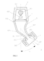
- FIG. 2 is a top cross-sectional view of the headphone device 1 illustrated in FIG. 1 .
- the lower side of the drawing sheet corresponds to the front side of the headphone device 1
- the right side of the drawing sheet corresponds to a right side of the headphone device 1
- the left side of the drawing sheet corresponds to a left side of the headphone device 1.
- the housing 2 is formed into a cylindrical shape.
- the housing 2 includes a recessed portion 201 that is open to the front side of the headphone device, and a hole 202 is formed in a lower portion of the housing 2.
- One end of the cable 6 is inserted into an inside of the housing 2 through the hole 202 of the housing 2, and the cable 6 forms a knot 601 inside the housing 2.
- the knot 601 prevents the cable 6 from falling out of the housing 2 downwardly.
- a lead wire 602 protrudes from the one end of the cable 6 that forms the knot 601 inside the housing 2.
- the driver unit 7 includes a diaphragm (not shown), and is electrically connected to the lead wire 602 of the cable 6.
- the driver unit 7 is fixed on an inner wall of a front portion of the housing 2 with an adhesive or the like.
- the nozzle section 3 has a hollow interior, and is formed into such a conical shape that an external shape of the nozzle section 3 is narrowed from a rear portion 302 toward a front portion 301. Further, as illustrated in FIG. 2 , the nozzle section 3 is formed so as to be inclined to the right side in an offset manner by an angle C with respect to the housing 2 in a region from the rear portion 302 toward the front portion 301. In this embodiment, an angle of the inclination is set to 40 degrees. The nozzle section 3 is inclined to the right side by the angle C with respect to the housing 2 in the region from the rear portion 302 toward the front portion 301.
- the nozzle section 3 includes an outwardly curved portion 306 that is formed at an intermediate portion of a left side surface of the nozzle section 3 so as to swell outwardly, and includes an inwardly curved portion 307 that is formed at an intermediate portion of a right side surface of the nozzle section 3 so as to swell inwardly.
- the rear portion 302 of the nozzle section 3 is fixed to a distal end portion of the housing 2 with an adhesive or the like.
- a protruding portion 303 is formed on a front part of the front portion 301 of the nozzle section 3.
- the protruding portion 303 is formed into a cylindrical shape, and has a hole 304 formed to penetrate therethrough in a fore-and-aft direction.
- the protruding portion 303 includes a groove portion 305 formed in a center portion of an outer periphery thereof.
- the ear pad 4 is formed of an elastic body such as a rubber member into a cylindrical shape.
- the ear pad 4 has a hole 401 formed to penetrate therethrough in the fore-and-aft direction.
- the ear pad 4 includes a flange portion 402 on an inner part on a rear side thereof. The ear pad 4 is held on a front side of the nozzle section 3 in such a manner that the flange portion 402 is fitted into the groove portion 305 of the protruding portion 303.
- the headphone device 1 includes an input terminal (not shown) provided at another end of the cable 6 that is inserted into the housing 2.
- the input terminal is connected to an output terminal of a reproducing device (not shown).
- the headphone device 1 inputs an audio signal output from the output terminal of the reproducing device, and emits, from the driver unit 7 through the cable 6, the audio signal input by the input terminal as sound.
- the user of the headphone device 1 causes the reproducing device to reproduce the audio signal under a state in which the user inserts the ear pad 4 into the ear.
- the audio signal reproduced by the reproducing device is emitted as sound by the driver unit 7 through the input terminal and the cable 6, and the audio signal emitted as sound is transmitted to an inside of the hole 401 of the ear pad 4 through an inside of the nozzle section 3.
- the user can listen to the audio signal output from the headphone device 1 in a state of wearing the headphone device 1 in the ear.
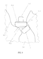
- FIG. 3 is a top view illustrating a state in which the headphone device 1 according to this embodiment is attached to the ear of the user.
- the upper side of the drawing sheet corresponds to an outer side of the ear of the user
- the right side of the drawing sheet corresponds to a front side of the user.
- a distal end of the ear pad 4 is inserted from an ear concha 501 toward an ear canal 502, and an outer peripheral portion of the ear pad 4 is held on an inner wall of an ear canal entrance 503.
- an inner wall of the ear canal entrance 503 inside the ear 50 protrudes forward from the inner side of the ear concha 501, and an inner wall of a tragus 504 is inclined forward in a region from an entrance of the ear 50 toward the inside of the ear.
- the nozzle section 3 is formed so as to be inclined to the right side by the angle C with respect to the housing 2 in the region from the rear portion 302 toward the front portion 301, and hence wearing comfort of the headphone device 1 can be enhanced.
- the headphone device 1 includes the outwardly curved portion 306 that is formed at the intermediate portion of the left side surface of the nozzle section 3 so as to swell outwardly. Accordingly, under a state in which the ear pad 4 is held in the ear canal entrance 503, the nozzle section 3 and a part of an outer periphery of the housing 2 do not partially press a swelling portion of the ear canal entrance 503 indicated by the arrow A in FIG. 3 , but abut on a swelling portion of the ear canal entrance 503 at a portion having a large area on the surface of the outwardly curved portion 306 of the nozzle section 3.
- the headphone device 1 includes the inwardly curved portion 307 that is formed at the intermediate portion of the right side surface of the nozzle section 3 so as to swell inwardly. Accordingly, under the state in which the ear pad 4 is held in the ear canal entrance 503, the nozzle section 3 and the outer peripheral portion of the housing 2 do not press a swelling portion of the tragus 504 indicated by the arrow B in FIG. 3 .
- the headphone device 1 includes the outwardly curved portion 306 that is formed at the intermediate portion of the left side surface of the nozzle section 3 so as to swell outwardly, and includes the inwardly curved portion 307 that is formed at the intermediate portion of the right side surface of the nozzle section 3 so as to swell inwardly. Accordingly, even when the user wears the headphone device 1 for a long period of time, it is possible to prevent the headphone device 1 from causing a pain inside the ear 50 because of continuous pressing of the headphone device 1 onto the inner wall portion of the ear canal entrance 503 and the inner wall portion of the tragus 504.
- the headphone device 1 of this embodiment under the state in which the headphone device 1 is inserted into the ear and the outer peripheral portion of the ear pad 4 is held on the inner wall of the ear canal entrance 503, the portion having a large area on the surface of the outwardly curved portion 306 of the nozzle section 3 abuts on the swelling portion of the ear canal entrance 503, but does not press the tragus 504.
- the audio signal output from the driver unit 7 is properly transmitted to the ear canal 502 of the ear 50 through the inside of the nozzle section 3 and the inside of the ear pad 4, and hence it is possible to enhance sound quality of the audio signal output by the headphone device 1.
- the headphone device 1 has a configuration in which the nozzle section 3 is formed so as to be inclined to the right side by 40 degrees with respect to the housing 2 in the region from the rear portion 302 toward the front portion 301.
- the angle of the inclination may be set to any angle other than 40 degrees in conformity to a shape of the ear of the user.
- the angle of the inclination of the nozzle section 3 may be changed freely, and the angle of the inclination of the nozzle section 3 may be changed into an arbitrary angle in accordance with preference of the user.
- the headphone device 1 includes the outwardly curved portion 306 that is formed at the intermediate portion of the left side surface of the nozzle section 3 so as to swell outwardly, and includes the inwardly curved portion 307 that is formed at the intermediate portion of the right side surface of the nozzle section 3 so as to swell inwardly.
- the headphone device 1 may have a configuration in which the inwardly curved portion 307 swelling inwardly is not formed at the intermediate portion of the right side surface of the nozzle section 3, and only the outwardly curved portion 306 swelling outwardly is formed at the intermediate portion of the left side surface of the nozzle section 3.
- the headphone device 1 includes the outwardly curved portion 306 that is formed at the intermediate portion of the left side surface of the nozzle section 3 so as to swell outwardly, and includes the inwardly curved portion 307 that is formed at the intermediate portion of the right side surface of the nozzle section 3 so as to swell inwardly.
- the headphone device 1 may have a configuration in which the outwardly curved portion 306 swelling outwardly is not formed at the intermediate portion of the left side surface of the nozzle section 3, and only the inwardly curved portion 307 swelling inwardly is formed at the intermediate portion of the right side surface of the nozzle section 3.
- the headphone device 1 includes the cable 6 for inputting the audio signal from the reproducing device, but the headphone device 1 may have such a configuration that the cable 6 is not provided and, for example, the driver unit 7 inputs the audio signal from the reproducing device through wireless communication.
- the headphone device 1 has the configuration in which the driver unit 7 inputs the audio signal from the reproducing device through wireless communication, and thus the headphone device 1 does not need to include the cable 6. Accordingly, when the user walks or jogs, wearing comfort of the headphone device 1 can be further enhanced.
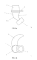
- FIGS. 4 are views illustrating the headphone device according to the another embodiment of the present invention.
- FIG. 4 (a) is a top view of the headphone device
- FIG. 4 (b) is a front view of the headphone device.
- the lower side of the drawing sheet corresponds to a front side of the headphone device
- the right side of the drawing sheet corresponds to a right side of the headphone device
- the left side of the drawing sheet corresponds to a left side of the headphone device.
- the upper side of the drawing sheet corresponds to an upper side of the headphone device
- the right side of the drawing sheet corresponds to the right side of the headphone device
- the left side of the drawing sheet corresponds to the left side of the headphone device.
- the headphone device has such a configuration that only a wing-like plate portion described below is added to the configuration of the headphone device 1 according to the above-mentioned embodiment, and hence description of the above-mentioned components is omitted.
- a headphone device 10 includes a wing-like plate portion 8 in addition to the above-mentioned components of the headphone device 1.
- the wing-like plate portion 8 is formed of an elastic body such as a rubber member or a plastic member, and is formed of a wing-shaped thin plate. A lower portion of the wing-like plate portion 8 is fixed to a front portion of the housing 2 so that the wing-like plate portion 8 is arranged above the front portion of the housing 2.
- the distal end of the ear pad 4 is inserted into the inside of the ear, and the outer peripheral portion of the ear pad 4 is held on the inner wall of the ear canal entrance.
- the wing-like plate portion 8 arranged above the housing 2 is fitted into a depressed portion of the ear concha.
- the ear pad 4 of the headphone device 10 is inserted into the inside of the ear, and the wing-like plate portion 8 abuts on an upper inner wall of the ear concha.
- the wing-like plate portion 8 abuts on the upper inner wall of the ear concha, and thus the headphone device 10 is correctly held in the depressed portion of the ear concha by the wing-like plate portion 8.
- the headphone device 10 similarly to the above-mentioned headphone device 1, the headphone device 10 according to the another embodiment of the present invention includes the outwardly curved portion 306 that is formed at the intermediate portion of the left side surface of the nozzle section 3 so as to swell outwardly.
- the nozzle section 3 and a part of the outer periphery of the housing 2 do not partially press the swelling portion of the ear canal entrance, and the portion having a large area on the surface of the outwardly curved portion 306 of the nozzle section 3 abuts on the swelling portion of the ear canal entrance.
- the headphone device 10 includes the inwardly curved portion 307 that is formed at the intermediate portion of the right side surface of the nozzle section 3 so as to swell inwardly.
- the user can wear the headphone device 10 in the ear under a state in which the nozzle section 3 and the outer peripheral portion of the housing 2 do not press the swelling portion of the tragus.
- the wing-like plate portion 8 abuts on the upper inner wall of the ear concha, and thus the headphone device 10 can be correctly held in the depressed portion of the ear concha.
- the wing-like plate portion 8 abuts on the upper inner wall of the ear concha, and thus the headphone device 10 is correctly held in the depressed portion of the ear concha. Accordingly, it is possible to prevent the ear pad 4 from falling out of the ear and prevent displacement of a position of wearing the ear pad 4 while the user wears the headphone device 10 in the ear.
- the headphone device 10 has such a configuration that the wing-like plate portion 8 is formed of a wing-shaped thin plate and is fixed to the housing 2 so as to be arranged above the front portion of the housing 2.
- the wing-like plate portion 8 may have any shape other than the wing-like shape as long period of as the wing-like plate portion 8 can be fitted into the depressed portion of the ear concha.
- the headphone device 10 may have a configuration in which the wing-like plate portion 8 is not fixed to the housing 2, but is fixed to, for example, the ear pad 4 or the nozzle section 3.
- the headphone device 10 has such a configuration that the wing-like plate portion 8 is fixed to the housing 2.
- the wing-like plate portion 8 may be removable from the housing 2 or the nozzle section 3 of the headphone device 10.
- a recessed portion is formed in an upper surface portion of the housing 2, and a protruding portion is formed on a bottom portion of the wing-like plate portion 8.
- the protruding portion of the wing-like plate portion 8 is configured to be fitted into the recessed portion of the housing 2, and thus the wing-like plate portion 8 is removable from the housing 2.
- the headphone device 10 can be shifted between a state of including the wing-like plate portion 8 and a state of not including the wing-like plate portion 8 in accordance with preference of the user, and hence it is possible to enhance convenience when wearing the headphone device 10 in accordance with the user's purpose, feeling in use, and the like.
- the wing-like plate portion 8 is formed of a thin plate.
- the wing-like plate portion 8 may be formed of, for example, a thin mesh material other than a thin plate member, or may have protrusions and recesses or a plurality of holes formed in the surface of the wing-like plate portion 8. With this configuration, it is possible to enhance a wearing feeling when the wing-like plate portion 8 touches the ear, and hence wearing comfort in a case of wearing the headphone device 10 in the ear can be further enhanced.
- the present invention can be effectively applied to the headphone device to be connected to the reproducing device through the cable, for outputting the audio signal output from the reproducing device.
Landscapes
- Engineering & Computer Science (AREA)
- Physics & Mathematics (AREA)
- Acoustics & Sound (AREA)
- Signal Processing (AREA)
- Manufacturing & Machinery (AREA)
- Headphones And Earphones (AREA)
Applications Claiming Priority (2)
| Application Number | Priority Date | Filing Date | Title |
|---|---|---|---|
| JP2011283068A JP2013135266A (ja) | 2011-12-26 | 2011-12-26 | ヘッドホン装置 |
| PCT/JP2012/078097 WO2013099429A1 (fr) | 2011-12-26 | 2012-10-31 | Dispositif formant casque d'écoute |
Publications (2)
| Publication Number | Publication Date |
|---|---|
| EP2809081A1 true EP2809081A1 (fr) | 2014-12-03 |
| EP2809081A4 EP2809081A4 (fr) | 2015-10-07 |
Family
ID=48696930
Family Applications (1)
| Application Number | Title | Priority Date | Filing Date |
|---|---|---|---|
| EP12861126.6A Ceased EP2809081A4 (fr) | 2011-12-26 | 2012-10-31 | Dispositif formant casque d'écoute |
Country Status (4)
| Country | Link |
|---|---|
| US (1) | US9197959B2 (fr) |
| EP (1) | EP2809081A4 (fr) |
| JP (1) | JP2013135266A (fr) |
| WO (1) | WO2013099429A1 (fr) |
Cited By (2)
| Publication number | Priority date | Publication date | Assignee | Title |
|---|---|---|---|---|
| EP3041259A1 (fr) * | 2014-12-31 | 2016-07-06 | Skullcandy, Inc. | Écouteur intra-auriculaire ayant une buse flexible et procédés associés |
| WO2021186182A1 (fr) * | 2020-03-19 | 2021-09-23 | Flare Audio Technologies Limited | Insert auriculaire |
Families Citing this family (9)
| Publication number | Priority date | Publication date | Assignee | Title |
|---|---|---|---|---|
| KR101601859B1 (ko) * | 2014-09-01 | 2016-03-09 | 크레신 주식회사 | 인 이어 이어폰 |
| EP3248394B1 (fr) * | 2015-01-19 | 2024-12-11 | 3M Innovative Properties Company | Dispositif de protection auditive avec pavillon acoustique en spirale |
| US9635452B2 (en) * | 2015-08-05 | 2017-04-25 | Bose Corporation | Noise reduction with in-ear headphone |
| USD817301S1 (en) | 2016-08-26 | 2018-05-08 | Apple Inc. | Headphones |
| USD845926S1 (en) | 2017-06-30 | 2019-04-16 | Apple Inc. | Earphones |
| CN108989933A (zh) * | 2018-07-16 | 2018-12-11 | 广州艺腾电子产品有限公司 | 耳机结构 |
| WO2020105197A1 (fr) * | 2018-11-25 | 2020-05-28 | 株式会社メイ | Écouteurs |
| CN210958692U (zh) * | 2020-02-25 | 2020-07-07 | 昆山众赢昌盛贸易有限公司 | 一种入耳式耳机 |
| USD980185S1 (en) | 2020-07-02 | 2023-03-07 | Apple Inc. | Earphones |
Family Cites Families (15)
| Publication number | Priority date | Publication date | Assignee | Title |
|---|---|---|---|---|
| US7522743B2 (en) * | 2002-01-07 | 2009-04-21 | Step Communications | High comfort sound delivery system |
| JP4709017B2 (ja) | 2006-01-12 | 2011-06-22 | ソニー株式会社 | イヤホン装置 |
| US8249287B2 (en) * | 2010-08-16 | 2012-08-21 | Bose Corporation | Earpiece positioning and retaining |
| KR100757462B1 (ko) * | 2006-07-14 | 2007-09-11 | 삼성전자주식회사 | 이어폰 |
| JP4778390B2 (ja) * | 2006-10-03 | 2011-09-21 | ホシデン株式会社 | ヘッドセット |
| US7986803B1 (en) * | 2007-05-10 | 2011-07-26 | Plantronics, Inc. | Ear bud speaker earphone with retainer tab |
| JP2009027675A (ja) * | 2007-07-24 | 2009-02-05 | Swcc Showa Device Technology Co Ltd | イヤホンアタッチメント |
| US8638970B2 (en) * | 2007-07-31 | 2014-01-28 | Burton Technologies, Llc | In-ear adapter for earbuds |
| DE102008047520B4 (de) * | 2008-09-16 | 2021-10-14 | Sennheiser Electronic Gmbh & Co. Kg | In-Ohr Hörer und Erweiterungsadapter |
| WO2009063096A2 (fr) * | 2009-02-13 | 2009-05-22 | Phonak Ag | Compartiment à plusieurs modules pour appareil auditif |
| JP5281436B2 (ja) * | 2009-02-26 | 2013-09-04 | 株式会社オーディオテクニカ | イヤホン |
| KR101742333B1 (ko) * | 2009-04-30 | 2017-05-31 | 베르토 메디칼 솔루션스, 엘엘씨 | 이어피스 시스템 |
| JP2011009909A (ja) * | 2009-06-24 | 2011-01-13 | Audio Technica Corp | イヤホン |
| TWM391239U (en) * | 2010-05-27 | 2010-10-21 | Comaxtech International Ltd | Improved structure for earphone |
| US8774434B2 (en) * | 2010-11-02 | 2014-07-08 | Yong D. Zhao | Self-adjustable and deforming hearing device |
-
2011
- 2011-12-26 JP JP2011283068A patent/JP2013135266A/ja active Pending
-
2012
- 2012-10-31 US US14/368,647 patent/US9197959B2/en active Active
- 2012-10-31 EP EP12861126.6A patent/EP2809081A4/fr not_active Ceased
- 2012-10-31 WO PCT/JP2012/078097 patent/WO2013099429A1/fr not_active Ceased
Cited By (5)
| Publication number | Priority date | Publication date | Assignee | Title |
|---|---|---|---|---|
| EP3041259A1 (fr) * | 2014-12-31 | 2016-07-06 | Skullcandy, Inc. | Écouteur intra-auriculaire ayant une buse flexible et procédés associés |
| US9961434B2 (en) | 2014-12-31 | 2018-05-01 | Skullcandy, Inc. | In-ear headphones having a flexible nozzle and related methods |
| WO2021186182A1 (fr) * | 2020-03-19 | 2021-09-23 | Flare Audio Technologies Limited | Insert auriculaire |
| US12137313B2 (en) | 2020-03-19 | 2024-11-05 | Flare Audio Technologies Limited | Ear insert |
| AU2021238937B2 (en) * | 2020-03-19 | 2026-02-19 | Flare Audio Technologies Limited | An ear insert |
Also Published As
| Publication number | Publication date |
|---|---|
| JP2013135266A (ja) | 2013-07-08 |
| US9197959B2 (en) | 2015-11-24 |
| EP2809081A4 (fr) | 2015-10-07 |
| WO2013099429A1 (fr) | 2013-07-04 |
| US20140369545A1 (en) | 2014-12-18 |
Similar Documents
| Publication | Publication Date | Title |
|---|---|---|
| US9197959B2 (en) | Headphone device | |
| EP3280158B1 (fr) | Aide auditive | |
| EP2953377B1 (fr) | Casque d'écoute sans fil monophonique | |
| EP2975859B1 (fr) | Composant élastomèrique pour écouteurs à oreillettes et écouteurs comprenant de tels composants élastomèriques | |
| CN202121744U (zh) | 一种耳机 | |
| US10791390B2 (en) | Flex-fit ear tip for headphones | |
| JP6026235B2 (ja) | ネックバンド型イヤーホン | |
| JP6544671B1 (ja) | イヤホン | |
| US9462369B2 (en) | Ambient and audio earphone system | |
| JP7626794B2 (ja) | 音響出力装置 | |
| US12160698B2 (en) | Audio device with wingtip anchor | |
| JP2013135266A5 (fr) | ||
| JP2021077991A (ja) | イヤホン、イヤホンのドライバ用カバー、およびカバーセット | |
| EP2456228A1 (fr) | Ecouteur et dispositif électronique | |
| JP7067477B2 (ja) | 音響出力装置 | |
| JP5355303B2 (ja) | イヤーパッド及びそれを有するイヤホン | |
| JP2013146371A (ja) | 血流センサ | |
| JP5592622B2 (ja) | イヤホン | |
| JP5795359B2 (ja) | イヤホン | |
| US11962965B2 (en) | Wireless earbud having external ear contact point | |
| CN120419209A (zh) | 开放式耳机 | |
| WO2024085248A1 (fr) | Écouteurs à bascule | |
| CN120435877A (zh) | 耳机 | |
| KR20230089777A (ko) | 골전도 압전 이어폰 |
Legal Events
| Date | Code | Title | Description |
|---|---|---|---|
| PUAI | Public reference made under article 153(3) epc to a published international application that has entered the european phase |
Free format text: ORIGINAL CODE: 0009012 |
|
| 17P | Request for examination filed |
Effective date: 20140711 |
|
| AK | Designated contracting states |
Kind code of ref document: A1 Designated state(s): AL AT BE BG CH CY CZ DE DK EE ES FI FR GB GR HR HU IE IS IT LI LT LU LV MC MK MT NL NO PL PT RO RS SE SI SK SM TR |
|
| DAX | Request for extension of the european patent (deleted) | ||
| RA4 | Supplementary search report drawn up and despatched (corrected) |
Effective date: 20150908 |
|
| RIC1 | Information provided on ipc code assigned before grant |
Ipc: H04R 1/10 20060101AFI20150902BHEP |
|
| STAA | Information on the status of an ep patent application or granted ep patent |
Free format text: STATUS: EXAMINATION IS IN PROGRESS |
|
| 17Q | First examination report despatched |
Effective date: 20181105 |
|
| REG | Reference to a national code |
Ref country code: DE Ref legal event code: R003 |
|
| 111Z | Information provided on other rights and legal means of execution |
Free format text: AL AT BE BG CH CY CZ DE DK EE ES FI FR GB GR HR HU IE IS IT LT LU LV MC MK MT NL NO PL PT RO RS SE SI SK SM TR Effective date: 20201204 |
|
| 111Z | Information provided on other rights and legal means of execution |
Free format text: AL AT BE BG CH CY CZ DE DK EE ES FI FR GB GR HR HU IE IS IT LT LU LV MC MK MT NL NO PL PT RO RS SE SI SK SM TR AL AT BE BG CH CY CZ DE DK EE ES FI FR GB GR HR HU IE IS IT LT LU LV MC MK MT NL NO PL PT RO RS SE SI SK SM TR Effective date: 20201204 |
|
| STAA | Information on the status of an ep patent application or granted ep patent |
Free format text: STATUS: THE APPLICATION HAS BEEN REFUSED |
|
| 18R | Application refused |
Effective date: 20210211 |