EP2809123A1 - Procédé et système pour réduire les interférences dans un réseau sans fil et programme informatique associé - Google Patents
Procédé et système pour réduire les interférences dans un réseau sans fil et programme informatique associé Download PDFInfo
- Publication number
- EP2809123A1 EP2809123A1 EP20130382201 EP13382201A EP2809123A1 EP 2809123 A1 EP2809123 A1 EP 2809123A1 EP 20130382201 EP20130382201 EP 20130382201 EP 13382201 A EP13382201 A EP 13382201A EP 2809123 A1 EP2809123 A1 EP 2809123A1
- Authority
- EP
- European Patent Office
- Prior art keywords
- base station
- phase
- radio resources
- serving base
- interfering
- Prior art date
- Legal status (The legal status is an assumption and is not a legal conclusion. Google has not performed a legal analysis and makes no representation as to the accuracy of the status listed.)
- Withdrawn
Links
Images





Classifications
-
- H—ELECTRICITY
- H04—ELECTRIC COMMUNICATION TECHNIQUE
- H04B—TRANSMISSION
- H04B7/00—Radio transmission systems, i.e. using radiation field
- H04B7/02—Diversity systems; Multi-antenna system, i.e. transmission or reception using multiple antennas
- H04B7/022—Site diversity; Macro-diversity
- H04B7/024—Co-operative use of antennas of several sites, e.g. in co-ordinated multipoint or co-operative multiple-input multiple-output [MIMO] systems
-
- H—ELECTRICITY
- H04—ELECTRIC COMMUNICATION TECHNIQUE
- H04J—MULTIPLEX COMMUNICATION
- H04J11/00—Orthogonal multiplex systems, e.g. using WALSH codes
- H04J11/0023—Interference mitigation or co-ordination
- H04J11/005—Interference mitigation or co-ordination of intercell interference
-
- H—ELECTRICITY
- H04—ELECTRIC COMMUNICATION TECHNIQUE
- H04L—TRANSMISSION OF DIGITAL INFORMATION, e.g. TELEGRAPHIC COMMUNICATION
- H04L27/00—Modulated-carrier systems
- H04L27/32—Carrier systems characterised by combinations of two or more of the types covered by groups H04L27/02, H04L27/10, H04L27/18 or H04L27/26
- H04L27/34—Amplitude- and phase-modulated carrier systems, e.g. quadrature-amplitude modulated carrier systems
- H04L27/3405—Modifications of the signal space to increase the efficiency of transmission, e.g. reduction of the bit error rate, bandwidth, or average power
- H04L27/3444—Modifications of the signal space to increase the efficiency of transmission, e.g. reduction of the bit error rate, bandwidth, or average power by applying a certain rotation to regular constellations
-
- H—ELECTRICITY
- H04—ELECTRIC COMMUNICATION TECHNIQUE
- H04L—TRANSMISSION OF DIGITAL INFORMATION, e.g. TELEGRAPHIC COMMUNICATION
- H04L5/00—Arrangements affording multiple use of the transmission path
- H04L5/003—Arrangements for allocating sub-channels of the transmission path
- H04L5/0058—Allocation criteria
- H04L5/0073—Allocation arrangements that take into account other cell interferences
Definitions
- the present invention generally relates to the field of wireless communications, and more particularly to a method and a system for reducing interference in a wireless network and computer program thereof by allowing a UE to receive from its serving base station a set of radio resources that will be orthogonal in the phase domain with the same radio resources used by an interfering base station.
- Single frequency radio networks like Long Term Evolution or LTE and LTE-Advanced or LTE-A suffer from a loss of performance for those mobile terminals located in the border coverage area between two or more base stations, because they can receive transmissions from its intended base station and at the same time and frequency receive unwanted interference from the neighbouring base stations.
- the unwanted interference yields a low signal to interference plus noise ratio, limiting the data rate the mobile terminal can support.
- the User Equipment or UE must receive from its serving base station or eNB a set of radio resources that should be orthogonal to the radio resources emitted by other base stations at the same time and in the same frequency.
- neighbour eNB's When neighbour eNB's share the same frequency band they must compete for the usage of the radio resources for providing service to mobile terminals located in the border coverage area between them. This means that when a given eNB schedules a radio resource, i.e. a set of Resource Blocks (RB), in the downlink to a particular UE, a neighbour eNB can schedule the same radio resources to another UE.
- a radio resource i.e. a set of Resource Blocks (RB)
- the main LTE and LTE-A physical layer procedure to manage the downlink radio resource assignment to a UE is based on the UE reporting back to the serving eNB which is the quality of the previously received radio resources.
- the UE measures the Signal to Noise plus Interference Ratio (SNIR) of the received downlink Reference Signals, based on instructions from the eNB.
- the UE can measure the average SNIR of the full downlink bandwidth, the SNIR of a set of best sub bands, or the SNIR of a set of sub bands that cover the full downlink bandwidth.
- CQI Channel Quality Indicator
- MCS Modulation and Coding Scheme
- CSI reporting is periodic or aperiodic.
- the periodic CSI reporting is supported by the Physical Uplink Control Channel (PUCCH), and the aperiodic CSI reporting is supported by the Physical Uplink Shared Channel (PUSCH).
- PUCCH Physical Uplink Control Channel
- PUSCH Physical Uplink Shared Channel
- the UE performs aperiodic CSI reporting using the PUSCH in uplink subframe n+k, upon decoding in downlink subframe n either a Downlink Control Information (DCI) format, or a Random Access Response Grant.
- DCI Downlink Control Information
- a CSI report is triggered if the CSI request field is set to '1'. If the CSI request field size is 2 bits, a CSI report is triggered according to the value in table 1.
- a UE In the case of periodic CSI Reporting using PUCCH, a UE is semi-statically configured by higher layers to periodically feedback different the CSI on the PUCCH using the reporting modes given in table 2.
- Almost Blank Subframe patterns (ABS).
- an eNB reserves some subframes in its frame for no transmission of data, in order to reduce the potential interference with other eNB's.
- the Almost Blank Subframe pattern is communicated to neighbouring eNB's through the X2 interface between them, and can be used by the neighbouring eNB's to decide their own Almost Blank Subframe pattern or take downlink radio resource scheduling decisions.
- the Almost Blank Subframe pattern Information Element exchanged through X2 is described in
- CoMP Cooperative Multi-Point transmission
- 3GPP TR 36.819 V11.1.0 The main scenarios envisioned by 3GPP for CoMP are:
- the CoMP techniques may be categorized into one of the following categories.
- CoMP requires downlink channel state information (CSI) feedback from the UE to the eNB's.
- the CSI can be explicit, reporting the channel as observed by the UE without assuming any transmission or receiver processing, or implicit, where the feedback (e.g. CQI/PMI/Rl) of a transmission format is derived using hypotheses of different transmission and/or reception processing.
- the feedback e.g. CQI/PMI/Rl
- coherent JT requires inter-eNB phase information, but no inter-eNB phase information is needed in the case of CS/CB or DPS.
- CSI is deduced by the UE from the downlink signals, making use of the eNB downlink Reference Signals (3GPP TS 36.211 V11.0.0 Section 6.10), for example Channel State Information reference signals (CSI-RS) may be used for CoMP to identify and measure the downlink channel status of multiple transmission points.
- CSI-RS Channel State Information reference signals
- FIG. 4 illustrates the concept of modulation diversity where it is considered a 16QAM constellation (left) and the rotated version (right).
- a Rayleigh fading channel by proper interleaving of the I and Q projection components, fading of the I and Q components can be made uncorrelated, and the rotated constellation exhibits order-2 diversity.
- Some authors have proposed signal constellation rotation and a dynamic I and Q components interleaving, based on radio channel propagation status feedback from the UE to the eNB, for example in 3GPP TS 36.211 V11.0.0 Section 7.1.
- OFDM/OQAM OFDM / Offset QAM
- OFDM/OQAM OFDM / Offset QAM
- the prototype function modulating each sub-carrier must be very well localized in the time domain, to limit the inter-symbol interference.
- This function must also guarantee orthogonality among sub-carriers and among multi-carrier symbols. Functions having these characteristics exist, which guarantee the orthogonality only in the real domain. Consequently, the complex QAM data stream must be separated into its two real components: real part I and imaginary part Q, the imaginary part being modulated with a half-symbol-duration shifted version of the modulation filter (thus the connotation Offset).
- OFDM/OQAM was proposed in 3GPP although not adopted in the current LTE standard.
- the coherence time of the propagation channel has an impact on the performance of the OFDM-modulated LTE signal and the CSI reporting procedures.
- Coherence time is the time duration over which the channel impulse response is considered to be not varying due to Doppler effects.
- large OFDM symbol duration is desirable to combat time-dispersion caused ISI, however, the large OFDM symbol duration can reduce the ability to combat the fast temporal fading, specially, if the symbol period is large compared to the channel coherence time, then the channel can no longer be considered as constant through the OFDM symbol.
- the LTE symbol duration is kept smaller than the minimum channel coherence time. Since the channel coherence time is inversely proportional to the maximum Doppler shift f d , the symbol duration T s is chosen such that: T s ⁇ ⁇ 1 f d
- Coherence time also affect the CSI reporting process, and the scheduling and adaptive Modulation and Coding Scheme (MCS) procedures.
- MCS Modulation and Coding Scheme
- the UE reports to the eNB the radio channel status in a given time, and then the eNB schedules radio resources to be provided to that UE a given time later, when the channel conditions may have changed.
- T c 9 / 16 ⁇ ⁇ f d
- Coherence time is important for the estimation of phase of the received OFDM signal.
- a radio signal When a radio signal is transmitted it suffers multi-path propagation between the transmitter and the receiver.
- the receiver will receive multiple copies of the same signal, with different relative amplitudes and delays.
- the first term, 2 cos ( ⁇ /2), is the amplitude of the resulting signal, and the term sin (wt+ ⁇ /2) indicates that the phase of the resulting signal is ⁇ /2.
- the term ⁇ /2 is constant with time.
- the phase of the received signal ⁇ /2 will vary with time.
- phase variation of the received signal makes it necessary for the receiver to continuously synchronize in phase with the transmitter, making use of the synchronization signals defined in LTE, because otherwise the received complex symbols modulated in every subcarrier would randomly rotate their phase with time.
- LTE modulation mapper is described in Error! Reference source not found. for BPSK, QPSK, 160AM, 64QAM, where the result of the modulation mapping is always a complex symbol with values in the I and Q axis.
- the LTE also makes use of the Physical downlink control channel (PDCCH) (3GPP TS 36.211 V11.0.0 Physical channels and modulation. Section 6.8).
- the physical downlink control channel carries scheduling assignments and other control information in the form of Downlink Control Information (DCI) Error! Reference source not found., which transports downlink or uplink scheduling information.
- DCI Downlink Control Information
- LTE also makes use of a standard communication interface between eNB's, the X2 interface.
- 3GPP Error! Reference source not found. specifies the radio network layer signalling procedures of the control plane between eNBs in E-UTRAN.
- the radio resources are organized in Resource Blocks, as it is specified in 3GPP TS 36.211 V11.0.0, Section 6.2.3.
- Resource blocks are used to describe the mapping of certain physical channels to resource elements.
- a physical resource block is defined as N symb DL consecutive OFDM symbols in the time domain and N sc RB consecutive subcarriers in the frequency domain, where N symb DL and N sc RB are given in the next table.
- a physical resource block thus consists of N symb DL ⁇ N sc RB resource elements, corresponding to one slot in the time domain and 180 kHz in the frequency domain.
- Physical resource blocks are numbered from 0 to N RB DL - 1 in the frequency domain.
- n PRB ⁇ k N sc RB ⁇ Table 3.
- the LTE eNB's can be synchronized in time and phase, making use of synchronization standards like IEEE 1588v2 or technologies like GPS. Time and phase synchronization between eNB's allows the coordination of radio resources between them.
- an LTE or LTE-A network it is useful to schedule radio resources to the served UE's that will not collide in frequency and time with the radio resources of neighbouring eNB's, in particular for UE's in the border area between neighbouring eNB's.
- the radio resource assignment solution based on the Channel Quality Indication does not ensure that the radio resources scheduled by one eNB will not collide with the radio resources scheduled by another eNB, because scheduling decisions based on CSI rely on channel status information before the actual scheduling is performed, and if the eNB's are uncoordinated they can decide to schedule resources in the same time and frequency.
- CoMP techniques try to overcome this limitation, by means of a coordination of the transmissions of different eNB's.
- Joint Processing CoMP When Joint Processing CoMP is used, the transmitted data must be available in the different eNB's at the same time, which increases the load of the eNB's backhaul.
- JT Joint Transmission
- DPS Dynamic Point Selection
- the data rate of the communication link between eNB's will be also high because it will be necessary to decide which will be the transmitting eNB for every resource to be sent to the UE.
- Coordinated Scheduling/Beamforming CoMP When Coordinated Scheduling/Beamforming CoMP is used, the transmitted data will be available in one single eNB but it will be necessary a coordination between eNB's in order to make scheduling decisions that avoid using the same radio resources by different eNB's.
- Coordinated Scheduling/Beamforming requires a high data rate communication link between eNB's, typically fibre links, to support the coordination process between them.
- Another drawback of the Coordinated Scheduling is that a given radio resource, in time and frequency, can only be used by one of the base station in order to avoid overlapping and interference with other base stations.
- the Almost Blank Subframe patterns solution provides a way to reduce interference to UE's in the border coverage area, but it has the following limitations:
- the invention relates to a reduction interference mechanism by which a UE receives from its serving base station a set of radio resources that will be orthogonal in the phase domain with the same radio resources used by an interfering base station.
- the proposed mechanism is implemented on the LTE-A radio interface and network.
- a method for reducing interference in a wireless network wherein at least one user device or UE wirelessly connected to at least one serving base station suffers interference from at least one interfering base station.
- the method in a characteristic manner and on contrary of the known proposals comprises the following steps:
- the serving base station and the interfering base station previous to perform said comparing step, send to said UE, by means of a Physical Downlink Control Channel (PDCCH), the phase of the generated radio resources, wherein said PDCCH indicates the relative phase of the generated radio resources with respect to the phase of the base station other radio resources, by means of a Phase Indicator.
- PDCCH Physical Downlink Control Channel
- the serving base station generates radio resources to its served UE which are modulated only by real numbers and in a single axis, for example the I axis, of a constellation diagram such as the IQ diagram.
- the interfering base station generates radio resources which are modulated only by real numbers and in a single axis of the IQ diagram which is orthogonal with the serving base station, for example the Q axis.
- the providing and the calculating steps are periodically executed, being the periodicity of the same order of magnitude than the coherence time of the radio channel.
- the calculated phase difference indication parameter can be represented by an integer indicating at least the absolute value of said phase difference or the phase change. Both low periodicity reporting and simple phase indication can ensure a low data load between the UE and its serving base station, and between the serving base station and the interfering one.
- the sending step of said phase coordination messages will be done through a standard X2 interface.
- the phase coordination messages are used in order to indicate if the phase of the interfering base station radio resources has to be increased or decreased, comprising: increasing the phase of the interfering base station radio resources if said phase coordination message indicates a given amount of phase increase, or decreasing the phase of the interfering base station radio resources if said phase coordination message indicates a given amount of phase decrease.
- the phase coordination messages received from the serving base station can indicate to the interfering base station to increase the phase of its radio resources' if the phase difference indication parameter reported by the UE is less than 90° ( ⁇ /2 radians), or can indicate to the interfering base station to decrease the phase of its radio resources' if the phase difference indication parameter reported by the UE is more than 90° ( ⁇ /2 radians).
- a system for reducing interference in a wireless network comprising as commonly in the field: at least one user device or UE; at least one serving base station; and at least one interfering base station, wherein said UE is wirelessly connected to said at least one serving base station and suffers interference from said at least one interfering base station.
- a computer program product on a non-transitory computer-readable medium executable by a microprocessor for reducing interference in a wireless network
- said computer program product comprising program code instructions configured for calculating the phase difference by means of a phase difference indication parameter between the assigned radio resources of at least one user device, received from at least one serving base station, and the same time and frequency radio resources used by at least one interfering base station.
- the present invention allows reducing the interference on a UE although the same radio resources are used by its serving base station and an interfering base station.
- the main usage scenario is a set of low power base stations, or microcells, located under the coverage area of a high power base station or macrocell, although other possible usage scenarios could be also set.
- the invention is a simple form of Cooperative Multi-point Transmission (CoMP) where data is only available at one base station, but as opposed to CS/CB it does not require coordination of scheduling decisions for every radio resource sent to the terminal, only periodic reporting of phase differences at a rate lower than the coherence time of the radio channel, and thus requiring a low data rate inter-site communication between base stations.
- CoMP Cooperative Multi-point Transmission
- the proposed method requires also an updated CSI report from the UE that includes the phase difference between the serving base station and the interfering base station, but not a complete UE-to-interfering base station radio channel status report. Moreover, it leaves the phase difference correction to the interfering (macro) station, ensuring a simple implementation in the serving (micro) stations.
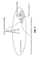
- Fig. 7 it is represented a typical usage scenario of the present invention, where the serving base station or eNB is a microcell and the interfering eNB is a high power macrocell, and therefore there will be only one dominant interfering eNB.
- An UE located in the border coverage area between the serving eNB and the interfering eNB can receive signals from both eNB's.
- the information about the interfering eNB identity will be provided to the UE by its serving eNB by means of the broadcast channel (BCH) and its implementation is not part of this invention.
- BCH broadcast channel
- the invention provides means to generate orthogonal Resource Blocks (RB's) in the interfering eNB with respect to the same RB's in the serving eNB.
- RB's orthogonal Resource Blocks
- both the serving eNB and the interfering eNB can use the same RB's in the time and frequency domain, increasing the overall capacity of the radio network. This is schematically described in Fig. 8 .
- the serving eNB can generate downlink radio resources to its served UE which are modulated only by real numbers and in a single axis, i.e. the I axis of the constellation diagram, in this particular case an IQ diagram.
- the interfering eNB can also generate radio resources which are modulated only by real numbers and in a single axis of the IQ diagram which is orthogonal with the serving base station, for example the Q axis.
- These downlink radio resources can be transported in the PDSCH or in the so called New Carrier Type (NCT) as it is under study in 3GPP for its release 12.
- NCT New Carrier Type
- This invention does not preclude any LTE physical channel for supporting these radio resources.
- the data to be sent in the downlink to the UE by means of these radio resources will be provided by a standard LTE DL-SCH transport channel, which will be labeled as Orthogonal DL-SCH (ODL-SCH) transport channel for identification purposes.
- ODL-SCH Orthogonal DL-SCH
- the ODL-SCH will be mapped to LTE OFDM radio resources following the next procedures:
- the ODL-SCH data is modulated in a set of resource element reserved for ODL-SCH transportation, by means of real valued symbols and along a single axis of the I/Q diagram.
- the serving eNB and the interfering eNB are time and phase synchronized at the LTE symbol level.
- the process of synchronization is not part of this invention, and can be done by means of any standard procedures, for example IEEE 1588v2.
- the PDCCH will report to the UE which resource elements in the PDSCH or in the NCT are used to map an ODL-SCH and scheduled to that UE, and which is the phase of the modulated symbols with respect to the phase reference of the LTE signal.
- the Downlink Control Information (DCI) transported by the PDCCH includes a new indicator, called "Phase Indicator", which will indicate if the scheduled resource elements for transporting the ODL-SCH are modulated with a phase difference with respect to the phase of the LTE signal.
- the serving eNB's will keep a phase of 0° of its modulated symbols with respect to the phase reference of the LTE signal, and thus the "Phase Indicator” will be 0°, and it will be the interfering eNB who will modulate its ODL-SCH supporting symbols with some phase differences with respect to the phase reference of its LTE signal, and thus its “Phase Indicators” will be different to 0°.
- the UE receives de PDCCH and the DCI information that it transports.
- the UE then makes use of the Phase Indicator in the modified DCI to determine if there are ODL-SCH resources scheduled to it in the PDSCH and their phase with respect to the LTE signal phase reference, in order to perform the correct demodulation of them.
- step 1 the UE calculates the phase difference between the received LTE signal from its serving eNB and the interfering LTE signal from an interfering eNB.
- the UE compares the phase difference between its scheduled radio resources for transporting the ODL-SCH and the same radio resources used by an interfering base station, making use of reference signals that are located in the spectral zone of the resource elements dedicated for transporting the ODL-SCH, in order to overcome non-frequency-flat propagation conditions.
- This invention does not preclude any inter-eNB phase difference estimation procedure, as they are already foreseen for coherent JT CoMP, and they are not part of this invention.
- the UE determines the phase difference between the serving eNB and the interfering eNB, step 2, it will provide a CSI feedback report to its serving eNB which includes the phase difference, by a means of Phase Difference Indicator (PDI) parameter.
- PDI Phase Difference Indicator
- the serving eNB will receive the PDI parameter from the UE and will report to the interfering eNB the phase correction it must perform, step 3.
- the goal of the phase correction process is to receive from the UE Phase Difference Indicator parameters as close as possible to 90° ( ⁇ /2 radians).
- the reporting between the serving eNB and the interfering eNB preferably will be done through the standard X2 interface, by means of phase coordination messages.
- the interfering base station continuously adjusts the phase of the RB's that it uses for transporting the ODL-SCH accordingly to the phase corrections indicated by the serving base station, in order to overcome time dependent phase variations due to multi-path propagation.
- Phase adjustment in the interfering eNB is done by means of the phase coordination messages received from the serving eNB.
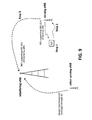
- the phase coordination messages received from the serving eNB will indicate to the interfering eNB to increase the phase of its RB's if the PDI reported by the UE is less than 90° ( ⁇ /2 radians), or will indicate to the interfering eNB to decrease the phase of its RB's if the PDI reported by the UE is more than 90° ( ⁇ /2 radians), as it is represented in the Fig. 10 .
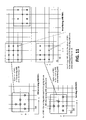
- the interfering eNB can also receive phase coordination messages from other serving eNB's under its coverage area, and adjust its common RB's phase accordingly. The result of these phase adjustments is to ensure the RB's received in the UE from its serving eNB and the interfering eNB are orthogonal in phase. This is schematically represented in Fig.11 .
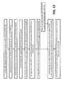
- Fig. 12 illustrates in a flow diagram the described processes followed by the present invention.
- the UE measures the relative phase, between the serving eNB and the interfering eNB, of RB's reserved in the PDSCH or in the NCT for transporting the ODL-SCH.
- the relative phase values measured by the UE for the RB's reserved for transporting the ODL-SCH can range from a maximum possible value (MaxValue) of 360° to a minimum possible value (MinValue) of 0°.
- the relative phase values are encoded in a set of predefined levels, in order to reduce the amount of data fed back to the serving eNB.
- the result of this encoding is the PDI.
- This invention does not preclude any procedure to assign the relative phase values to predefined levels.
- the predefined levels and their corresponding PDI's are uniformly set from 0 to n, being PDI 0 assigned to the lowest possible range of relative phase, and n to the highest possible range of relative phase.
- PDI index encoding PDI Index Relative phase (°) 0 MinValue to (MinValue + ⁇ ) 1 (MinValue + ⁇ ) to (MinValue + 2 ⁇ ) ... ... n (MaxValue - ⁇ ) to MaxValue
- the predefined levels and their corresponding PDI's are non-uniformly set, in the sense that some PDI index values will correspond to a higher range of relative phases than other PDI index values.
- the PDI's corresponding to a smaller range will be those around 90° ( ⁇ /2 radians), in order to allow a more accurate feedback of the relative phase when the algorithm described in Error! Reference source not found. converges around 90°.
- the PDI encoding would be as follows, where ⁇ b > ⁇ s. Table 5.
- the predefined levels and their corresponding PDI's are assigned taking into account the change of relative phases between different CSI reports, not the absolute values of the relative phases measured by the UE.
- the relative phase change between measures will be low and reporting relative phase changes can require fewer bits for reporting, or relative phase change can be reported more accurately.
- relative phase changes are coded as follows, where ⁇ Phase is an arbitrarily set value of relative phase change. Table 6. PDI index encoding PDI Index Relative phase change (°) m (m-1) ⁇ to m ⁇ ... ... 1 ⁇ to 2 ⁇ 0 - ⁇ to ⁇ -1 - ⁇ to -2 ⁇ ... ... -m -(m-1) ⁇ to -m ⁇
- the result of this encoding is a PDI, which is reported from the UE to its serving eNB in the CSI reporting, indicating the phase difference of the radio resources reserved for transporting the ODL-SCH to that UE.
- the present invention distinctiveness includes the PDI as a new parameter to be reported in the Channel State Information (CSI).
- the CSI will then consist of the PDI, along the currently used parameters (CQI, PMI, PTI, RI), and its reporting will be controlled by the eNB.
- the Channel State Information in yet other embodiments, can include both the PDI and the CQI, along with eventually the other CSI parameters or, on another hand, the PDI but not the CQI, in order to reduce the traffic load in the uplink.
- the CSI reporting is always controlled by the eNB and different procedures can be implemented to require the UE to send the PDI instead of the CQI, and this invention does not restrict to any single procedure.
- PDI is sent by means of periodic CSI Reporting using PUCCH, where a UE is semi-statically configured by higher layers to periodically feedback different CSI (PDI, CQI, PMI, PTI, and/or RI) on the PUCCH using the reporting modes given in the next table.
- Periodic reporting is preferred because it will be necessary to periodically report the phase difference between the eNB signal and the interfering eNB signal, which will be constantly changing.
- reporting modes 1-0, 1-1, 2-0 and 2-1 are modified in order to include the provision of the PDI parameter along with the CQI parameter.
- the definition of reporting modes can be found in 3GPP TS 36.213 V11.0.0.
- the PDI parameter is used in the serving eNB to generate a phase coordination message, which is sent from the serving eNB to the interfering eNB through the X2 interface.
- phase coordination To this end, the X2 Application Protocol (X2AP) defined in 3GPP TS 36.423 V11.0.0 (X2AP), must include a new Global Procedure called "phase coordination".
- the purpose of the phase coordination procedure is to transfer relative phase correction information of resource elements supporting ODL-SCH channels in the interfering eNB, between the serving eNB and the interfering eNB.
- the serving eNB initiates the phase coordination procedure by sending a phase coordination message to the interfering eNB.
- the phase coordination message is sent by the serving eNB to the interfering eNB to transfer ODL-SCH relative phase correction information.
- the phase coordination message has the following structure: IE/Group Name Presence IE type and reference Semantics description Message Type PHASE COORDINATION Cell Information >Cell Information Item >>Cell ID Mandatory As it is defined in 3GPP 36.423 section 9.2.14 ld of the source cell >>Relative Phase Correction IE Mandatory Phase correction to apply >>RB Use IE Optional RB's to which phase correction must be applied
- the phase coordination message includes Cell ID of the serving eNB, the Relative Phase Correction IE and the RB Use IE.
- the Relative Phase Correction IE indicates the phase correction to be applied to the RB's supporting ODL-SCH channels in the interfering eNB.
- the serving eNB calculates the Relative Phase Correction IE taking into account the PDI reported by the UE, and any other parameter that could be useful for improving the relative phase correction at the interfering eNB.
- the Relative Phase Correction IE will be the opposite of the PDI as it was reported by the UE.
- IE/Group Name Presence IE type and reference Relative Phase Correction IE Mandatory ⁇ °, or -PDI
- the RB Use IE provides information about which RB's the serving eNB is going to use.
- the RB Use IE provides information about which sub frames the serving eNB is configuring as subframes to be used for ODL-SCH. These subframes will be preferred by the serving eNB for scheduling RB's for ODL-SCH transport.
- RB Use IE is optional, because if not sent the interfering eNB can assume that the serving eNB will use the RB's reported in previous phase coordination messages.
- RB Use IE Optional BIT STRING (SIZE(10)) Each position in the bitmap represents a DL subframe, for which value "1" indicates 'Used' and value "0" indicates 'non Used'. The first position corresponds to subframe 0 in a radio frame. The maximum number of subframes is 10.
- the RB Use IE provides information about which RB's in a subframe the serving eNB is configuring as used RB's for ODL-SCH transport.
- the RB use IE can include the following information:
- the interfering eNB makes use of the Relative Phase Correction IE and the RB Use IE of the phase coordination messages it receives from the serving eNB's to correct the phase of its transmitted RB's that make use of the same time and frequency radio resources than the serving eNB, as it is illustrated in the Fig.13 .
- the RB's used by the interfering eNB to transport its ODL-SCH channels once their phase correction has been done based on the information of the Relative Phase Correction IE's in the phase coordination messages, will be orthogonal in phase at the UE with respect to the RB's used by the serving eNB to transport its ODL-SCH channels.
- the interfering eNB reports to its UE's, by means of the PDCCH, which RB's in the PDSCH or in the NCT are used to map an ODL-SCH scheduled to every UE, and which is the phase of the modulated symbols with respect to the phase reference of the LTE signal.
- the phase difference is measured with respect to the phase indicated by the Primary and Secondary Synchronization signals.
- the phase difference affects all the resource elements scheduled to the UE, including the UE-specific reference signals.
- the DCI formats transported by the PDCCH will include a new indicator, called "Phase Indicator", which indicates if the scheduled resource elements for transporting the ODL-SCH are modulated with a phase difference with respect to the Primary and Secondary Synchronization signals.
- Phase Indicator indicates if the scheduled resource elements for transporting the ODL-SCH are modulated with a phase difference with respect to the Primary and Secondary Synchronization signals.
- This invention does not preclude any realization of this Phase Indicator, for example it could be an integer from 0 to 360, indicating the phase in degrees.
- the UE served by the interfering eNB receives de PDCCH and the DCI information that it transports, and makes use of the Phase Indicator in the DCI to determine if there are ODL-SCH resources scheduled to it in the PDSCH and their phase with respect to the LTE signal phase reference, in order to perform the correct demodulation of them.
- the RB's that are used for transporting the ODL-SCH, both in the serving eNB and in the interfering eNB, are modulated with real valued symbols.
- the procedure for generating the real valued symbols is not part of this invention. For example, it is possible to generate sequences of real valued numbers by means of the rotation of a complex valued constellation and a projection of the resulting rotated complex values into the I and Q axis, as it is described in 3GPP TSG RAN WG1 #31, Document R1-030156. In this way an M-QAM constellation is transformed into two real valued projections, with M values per projection.
- This invention does not preclude any procedure, and the only requisite is that the RB's that transport the ODL-SCH are modulated with real valued symbols.
Landscapes
- Engineering & Computer Science (AREA)
- Signal Processing (AREA)
- Computer Networks & Wireless Communication (AREA)
- Mobile Radio Communication Systems (AREA)
Priority Applications (1)
| Application Number | Priority Date | Filing Date | Title |
|---|---|---|---|
| EP20130382201 EP2809123A1 (fr) | 2013-05-30 | 2013-05-30 | Procédé et système pour réduire les interférences dans un réseau sans fil et programme informatique associé |
Applications Claiming Priority (1)
| Application Number | Priority Date | Filing Date | Title |
|---|---|---|---|
| EP20130382201 EP2809123A1 (fr) | 2013-05-30 | 2013-05-30 | Procédé et système pour réduire les interférences dans un réseau sans fil et programme informatique associé |
Publications (1)
| Publication Number | Publication Date |
|---|---|
| EP2809123A1 true EP2809123A1 (fr) | 2014-12-03 |
Family
ID=48576927
Family Applications (1)
| Application Number | Title | Priority Date | Filing Date |
|---|---|---|---|
| EP20130382201 Withdrawn EP2809123A1 (fr) | 2013-05-30 | 2013-05-30 | Procédé et système pour réduire les interférences dans un réseau sans fil et programme informatique associé |
Country Status (1)
| Country | Link |
|---|---|
| EP (1) | EP2809123A1 (fr) |
Cited By (2)
| Publication number | Priority date | Publication date | Assignee | Title |
|---|---|---|---|---|
| WO2017172139A1 (fr) * | 2016-03-31 | 2017-10-05 | Intel IP Corporation | Dispositif de communication et procédé de stockage de données |
| CN109076398A (zh) * | 2016-02-23 | 2018-12-21 | 软银股份有限公司 | 通信系统、基站和通信控制方法 |
Citations (3)
| Publication number | Priority date | Publication date | Assignee | Title |
|---|---|---|---|---|
| EP0865172A2 (fr) * | 1997-03-12 | 1998-09-16 | Nokia Mobile Phones Ltd. | Procédé et appareil pour opérer un système de radiocommunication intérieur à AMDC |
| WO2011088465A1 (fr) * | 2010-01-18 | 2011-07-21 | Qualcomm Incorporated | Procédés et appareils facilitant la coordination des brouillages intercellulaires par l'intermédiaire de l'indicateur de charge radio et de la puissance d'émission relative en bande étroite |
| US20120208467A1 (en) * | 2011-02-11 | 2012-08-16 | Wang Sherwin J | Method, system and apparatus using multiple feedbacks for uplink closed-loop beamforming |
-
2013
- 2013-05-30 EP EP20130382201 patent/EP2809123A1/fr not_active Withdrawn
Patent Citations (3)
| Publication number | Priority date | Publication date | Assignee | Title |
|---|---|---|---|---|
| EP0865172A2 (fr) * | 1997-03-12 | 1998-09-16 | Nokia Mobile Phones Ltd. | Procédé et appareil pour opérer un système de radiocommunication intérieur à AMDC |
| WO2011088465A1 (fr) * | 2010-01-18 | 2011-07-21 | Qualcomm Incorporated | Procédés et appareils facilitant la coordination des brouillages intercellulaires par l'intermédiaire de l'indicateur de charge radio et de la puissance d'émission relative en bande étroite |
| US20120208467A1 (en) * | 2011-02-11 | 2012-08-16 | Wang Sherwin J | Method, system and apparatus using multiple feedbacks for uplink closed-loop beamforming |
Cited By (3)
| Publication number | Priority date | Publication date | Assignee | Title |
|---|---|---|---|---|
| CN109076398A (zh) * | 2016-02-23 | 2018-12-21 | 软银股份有限公司 | 通信系统、基站和通信控制方法 |
| CN109076398B (zh) * | 2016-02-23 | 2023-05-16 | 软银股份有限公司 | 通信系统、基站和通信控制方法 |
| WO2017172139A1 (fr) * | 2016-03-31 | 2017-10-05 | Intel IP Corporation | Dispositif de communication et procédé de stockage de données |
Similar Documents
| Publication | Publication Date | Title |
|---|---|---|
| CN110771063B (zh) | 在无线通信系统中报告信道状态的方法和装置 | |
| US10057031B2 (en) | Method and apparatus for estimating channel in wireless communication system | |
| RU2723669C1 (ru) | Конфигурация pt-rs, зависящая от параметров планирования | |
| US9749106B2 (en) | Method and device for transmitting channel state information in wireless communication system | |
| RU2581037C2 (ru) | Способ сообщения информации о состоянии канала, базовая радиостанция, пользовательский терминал и система радиосвязи | |
| JP6374166B2 (ja) | 無線基地局、ユーザ端末及び無線通信方法 | |
| US10455514B2 (en) | Method and device for transmitting signal in wireless communication system | |
| CN107466452B (zh) | 报告信道状态的方法及其装置 | |
| US9979454B2 (en) | Radio communication system and method for feeding back a plurality of pieces of channel state information under coordinated multi-point transmission | |
| US9629010B2 (en) | Method for transmitting and receiving the channel state information and apparatus thereof | |
| EP2868020B1 (fr) | Methode et station de base pour adaptation de liaison de canal pdcch dans un systeme de communication radio | |
| US9698951B2 (en) | Method and apparatus for transmitting/receiving channel state information in wireless communication system | |
| CN110460409A (zh) | 用于发送和接收下行链路控制信息的方法和设备 | |
| CN107438955A (zh) | 在使用多个天线的无线通信系统中控制传输功率的方法和设备 | |
| US20160353317A1 (en) | Method and apparatus for removing interference and receiving signal in wireless communication system | |
| WO2015046266A1 (fr) | Dispositif réseau et terminal utilisateur | |
| CN108292966B (zh) | 用于先进的无线网络中的数据通信的方法和系统 | |
| CN115606159B (zh) | 幅度调制的相位跟踪参考信号 | |
| EP2809123A1 (fr) | Procédé et système pour réduire les interférences dans un réseau sans fil et programme informatique associé | |
| US20250300776A1 (en) | Efficient reference signals configuration for multi-user uplink transmissions | |
| CN121586999A (zh) | 在多trp系统中用于波束切换的方法和装置 | |
| JP2018191321A (ja) | 無線基地局及びユーザ端末 |
Legal Events
| Date | Code | Title | Description |
|---|---|---|---|
| PUAI | Public reference made under article 153(3) epc to a published international application that has entered the european phase |
Free format text: ORIGINAL CODE: 0009012 |
|
| 17P | Request for examination filed |
Effective date: 20130530 |
|
| AK | Designated contracting states |
Kind code of ref document: A1 Designated state(s): AL AT BE BG CH CY CZ DE DK EE ES FI FR GB GR HR HU IE IS IT LI LT LU LV MC MK MT NL NO PL PT RO RS SE SI SK SM TR |
|
| AX | Request for extension of the european patent |
Extension state: BA ME |
|
| STAA | Information on the status of an ep patent application or granted ep patent |
Free format text: STATUS: THE APPLICATION IS DEEMED TO BE WITHDRAWN |
|
| 18D | Application deemed to be withdrawn |
Effective date: 20150604 |