EP2809406B1 - Dispositif d'ancrage pour piquets de slalom et de délimitation - Google Patents
Dispositif d'ancrage pour piquets de slalom et de délimitation Download PDFInfo
- Publication number
- EP2809406B1 EP2809406B1 EP13702423.8A EP13702423A EP2809406B1 EP 2809406 B1 EP2809406 B1 EP 2809406B1 EP 13702423 A EP13702423 A EP 13702423A EP 2809406 B1 EP2809406 B1 EP 2809406B1
- Authority
- EP
- European Patent Office
- Prior art keywords
- core
- anchoring device
- head
- anchoring
- pin
- Prior art date
- Legal status (The legal status is an assumption and is not a legal conclusion. Google has not performed a legal analysis and makes no representation as to the accuracy of the status listed.)
- Not-in-force
Links
- 238000004873 anchoring Methods 0.000 title claims description 51
- 239000000463 material Substances 0.000 claims description 12
- 230000009849 deactivation Effects 0.000 claims description 4
- 230000004913 activation Effects 0.000 claims description 3
- 238000000605 extraction Methods 0.000 claims description 2
- 230000008901 benefit Effects 0.000 description 3
- 230000035515 penetration Effects 0.000 description 2
- 241000446313 Lamella Species 0.000 description 1
- XAGFODPZIPBFFR-UHFFFAOYSA-N aluminium Chemical compound [Al] XAGFODPZIPBFFR-UHFFFAOYSA-N 0.000 description 1
- 229910052782 aluminium Inorganic materials 0.000 description 1
- 230000000593 degrading effect Effects 0.000 description 1
- 230000000694 effects Effects 0.000 description 1
- 238000002474 experimental method Methods 0.000 description 1
- 238000007373 indentation Methods 0.000 description 1
Images




Classifications
-
- A—HUMAN NECESSITIES
- A63—SPORTS; GAMES; AMUSEMENTS
- A63C—SKATES; SKIS; ROLLER SKATES; DESIGN OR LAYOUT OF COURTS, RINKS OR THE LIKE
- A63C19/00—Design or layout of playing courts, rinks, bowling greens or areas for water-skiing; Covers therefor
- A63C19/06—Apparatus for setting-out or dividing courts
- A63C19/062—Slalom gate poles, posts or marking sticks for sport fields
-
- E—FIXED CONSTRUCTIONS
- E04—BUILDING
- E04H—BUILDINGS OR LIKE STRUCTURES FOR PARTICULAR PURPOSES; SWIMMING OR SPLASH BATHS OR POOLS; MASTS; FENCING; TENTS OR CANOPIES, IN GENERAL
- E04H12/00—Towers; Masts or poles; Chimney stacks; Water-towers; Methods of erecting such structures
- E04H12/22—Sockets or holders for poles or posts
-
- E—FIXED CONSTRUCTIONS
- E04—BUILDING
- E04H—BUILDINGS OR LIKE STRUCTURES FOR PARTICULAR PURPOSES; SWIMMING OR SPLASH BATHS OR POOLS; MASTS; FENCING; TENTS OR CANOPIES, IN GENERAL
- E04H12/00—Towers; Masts or poles; Chimney stacks; Water-towers; Methods of erecting such structures
- E04H12/22—Sockets or holders for poles or posts
- E04H12/2207—Sockets or holders for poles or posts not used
- E04H12/2215—Sockets or holders for poles or posts not used driven into the ground
- E04H12/223—Sockets or holders for poles or posts not used driven into the ground with movable anchoring elements; with separately driven anchor rods
Definitions
- the present invention relates to an anchoring device for boundary and goal bars, in particular for goals of skiing according to the preamble of claim 1.
- the anchoring unit consists of a hexagonal or round section with flexible brushes projecting thereon. In this case, a hole is excluded and then it is sufficient to insert the flexible rod in the snow. Experiments have shown that more or less forms a secure anchorage. However, this system is difficult to disassemble. For this purpose, holes must be made adjacent to the snow anchored rod so that the snow is loosened and the rod can be removed. If you drill too close to these brushes anchored in the snow, they will be wound up and damaged by the drill. This system is more or less fast to build, but can be broken down only with great expenditure of time.
- a rod is described as in the above-mentioned patent, which also in the region of its lower end a rotatable relative to the Torlaufstangen Economics actuating sleeve and a projection are provided which engages in an elongated receiving the anchoring element, such that upon rotation of the Torlaufstangen stressess relative to the actuating sleeve, the anchoring element is activated or deactivated.
- a plate for anchoring the door running rod provided in the snow, whose plate plane is substantially parallel to the longitudinal extent of the running rod. The plate is attached to the actuating sleeve. In this case, however, the plate also serves to actuate the actuating sleeve.
- the object of the present invention is to solve the above problems and to propose an anchoring device which allows both a centered and stable anchoring of the bars and, moreover, an easily removable bar after the deactivation of the anchoring.
- This object is achieved by an anchoring device for rods according to the characterizing part of claim 1. It is therefore proposed a rod tip with an inner core, preferably made of aluminum and an outer sleeve, preferably in plastic, which is comparable to the known expandable dowels.
- a hole is excluded, then the flexible rod is introduced into the bore and is activated by means of a lifting device.
- the lifting device consists of an alternately on the core or on the expansion sleeve provided cam, such that the expansion sleeve can be adjusted relative to the core.
- the lifting mechanism consists of a bolt which extends transversely to the longitudinal axis and, when rotated on a thread-like contour, moves upwards on the outer sleeve.
- a downward movement of the rod is necessary to activate the anchoring task.
- the new system is activated by moving the rod upwards. Moreover, only a quarter turn is necessary to get the desired effect.
- This has the advantage that there are no unwanted reciprocating movements, ie within the levels occupied by the axis of the rod during activation, which loosen the snow.
- the activation of the system takes place in that the conical part of the inner core spreads at least two sections of the outer sleeve.
- the lamellae present on the outer shell engage with the snow and cause the actual attachment / anchoring in the snow. If you want to disable the mechanism, it is sufficient to rotate the inner core with the actual rod vice versa.
- the rod moves downwards and the voltages which result only when activated in the subregion of the outer jacket return to their initial position in the case of a spring.
- the at Deactivation may hinder the closure of the portions of the outer shell, it is advantageous to previously install in the respective spaces between the protruding slats a rubber-like ring such as a bicycle tube, which has the advantage that these rings in the deactivation, the return of the side portions of the outer shell in support the original position.
- the elevator consists of a ramp in the region of the core head which extends from the core head alternately about the axis of the core and to act on the corresponding end of the expansion sleeve to compress or spread them with rotation of the head.
- the rod including the ski-mounted inner core
- a cam which is alternately provided on the core or on the sleeve, for example in the form of a wedge.
- the partial areas of the outer shell open by being spread open, and the lamellae existing on it anchor themselves in the snow.
- the system is activated this way.
- the system is deactivated and the rod can be easily removed by providing inclined planes in the direction of the axis of the core head, which guide the sleeve in the direction Press the axle itself, so the lamellae are freed from the snow.
- reference numeral 1 in its entirety indicates an anchoring device for ski-perch limiting rods according to the invention.
- the device 1 is connected to a rod 2 via an upper portion 3, which is connected via a flexible part 4 with a lower portion 5.
- This latter is connected to a core 6, which ends at its free end with a conical head 7.
- a bolt 8 which projects from the core perpendicular to its axis.
- the core 6 is surrounded by a dowel 100.
- This has a cam 9 at the upper edge of the wall of the anchor 100, which cooperates with the bolt 8.
- the cam surface 9 ends at the beginning of its slope with a recess 8 and at the end of its slope with a recess 11.
- the indentations 8 and 9 form the stop position of the bolt eighth
- the dowel 100 has a complete pipe section 12 and after this a longitudinally slotted pipe section 13 with slots 14 which form sectors 15. Of the sectors are radially before a plurality of anchoring fins 16.
- the anchoring lamellae 16 are connected to each other by longitudinal ribs 17.
- the sectors 15 are preferably surrounded by elastic seals 26 which cover the slots 14 to prevent snow or material of any nature from entering towards the core 6.
- the complete pipe section has longitudinal webs 18 which end up in a recess 19 provided with recesses 20.
- the operation of the anchoring device according to the invention is as follows.
- the dowel 100 is dimensioned such that this at Rotation from a position in which the bolt 8 is located in the recess 10, in a position in which the bolt 8 is located in the recess 11, after the device itself was driven according to the arrow 21 in the snow cover 22.
- the conical head 7 is pressed against the dowel by this is spread, with the consequent engagement of the fins 16 in the bore of the snow cover 22.
- the stroke "b" of the dowel 100 is expanded in the manner of a dowel known type.
- the conical head 7 could be connected to the core 6 by means of an adjustable screw 25 so as to increase or decrease the spread of the fins 16, or increase or decrease its penetration into the snow: thus, smaller penetration is needed when the snow is frosted and bigger when it's soft.
- the setting limits are indicated by "a”, for example.
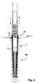
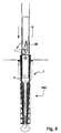
- the cam could also be formed by an inclined plane and wedge 27, which is adjustable between the bolt 8 and the shoulder 19, or as in FIG. 5 shown could be between the core 6 and the plug 100, an eccentric lever 28th act to compress the plug 100, so as to obtain the desired spread.
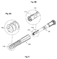
- FIGS. 6 to 8 show a second embodiment in which an expansion body is provided at 200 of an anchoring device 101 for limiting and goal bars.
- a core 106 has a head 107 and on the side facing away from the head 107 an extension 108 which merges with a tapered portion 109. It is fastened together with a bolt 110.
- a top pot 111 in the spreader 200 can be pushed.
- the pot 111 can be fastened to the extension 108 by means of screws 112.
- From the top pot 111 extend radially ribs 113 to depress the core itself in the recessed in the snow hole.
- a ramp 114 which is directed to the opening of the spreader 200, with the possibility of compressing the spreader 200 while rotating the head 107.
- wedges 115 are provided, which are inclined in the direction of the axis of the core 106 such that a concave shape is obtained to the Absorb the end of the spreader 200, where so the end of the spreader 200 is narrowed in the direction of its axis, whereby the extract of the spreader 200 is facilitated from the snow, the slats of the spreader are pulled out of the same.
- the anchoring device 101 is provided with ramps 114 which narrow over a step in an end-side ridge 117 which is dimensioned such that it can be taken up by an end-side longitudinal recess 116, which is excluded at the end within the expansion body 200: thus becomes a Rotation of the anchoring device 101 relative to the expansion body avoided.
- the anchor may have bristles or movable blades which are mounted on the outer part or inner part, which can be changed in their orientation by a rotary movement or lifting movement. If the armature is spread or activated, then the bristles or movable blades are in a position which complicates the release of the anchor or pulling out of the anchorage. When the armature is deactivated, the bristles or moving lamellas return to their original position, which thus facilitates their extraction.
- the bristles or fins can be made of a flexible material or from another material from which the actual anchorage is made.
- the entire anchorage can be made of different materials.
- the side flanges 18 are of a softer material, or e.g. the main body is made of hard material, and the fins (16) are made of a softer material. So a combination of different materials.
- the surfaces can be treated differently. Rough surface, smooth surface or a combination with each other.
Landscapes
- Engineering & Computer Science (AREA)
- Architecture (AREA)
- Civil Engineering (AREA)
- Structural Engineering (AREA)
- Footwear And Its Accessory, Manufacturing Method And Apparatuses (AREA)
- Piles And Underground Anchors (AREA)
- Discharge Heating (AREA)
- Glass Compositions (AREA)
- Polymers With Sulfur, Phosphorus Or Metals In The Main Chain (AREA)
Claims (15)
- Dispositif d'ancrage pour piquets de slalom et de délimitation pour la pratique du ski, comprenant une âme (6) à fixer à une extrémité d'un piquet (2) et des éléments d'ancrage (16), ledit dispositif d'ancrage étant composé d'une tête (7, 107) dépassant de l'extrémité de l'âme (6) ainsi que d'une cheville (100), et comprenant un corps tubulaire caractérisé en ce que le corps tubulaire est disposé de manière expansible entre la tête (7, 107) et la fixation du piquet (2) au moyen d'un système de levage comprenant une came (9, 114) prévue alternativement sur l'âme ou sur le corps expansible de telle sorte que le corps expansible soit décalé par rapport à l'âme.
- Dispositif d'ancrage selon la revendication 1, caractérisé en ce qu'il est constitué d'une âme (6) composée d'une tête conique (7) dépassant d'une extrémité de l'âme (6), d'un boulon positionné transversalement par rapport à l'axe de l'âme (6) à l'extrémité opposée de la tête conique (7) et d'une cheville (100) comprenant un corps tubulaire disposé de manière expansible entre la tête conique (7, 107) de l'âme et le boulon et présentant une came (9) sur la partie d'extrémité conique (7) de l'extrémité utilisée, ladite came étant poussée avec le boulon (8) et la - rotation du piquet (2) depuis une position dans laquelle le corps expansible (100) est détendu à une position dans laquelle la tête conique (7) est poussée contre la came (9) sous l'action du boulon (8) pour agir sur le corps de manière à le soumettre à des contraintes d'expansion radiale.
- Dispositif selon la revendication 1, caractérisé en ce que le système de levage comprend une rampe (114) dans la zone de la tête de l'âme (107) s'étendant à partir de la tête de l'âme tout autour de l'axe de l'âme et agissant sur l'extrémité correspondante du corps expansible afin de comprimer ce dernier ou d'écarter l'axe par rotation de la tête.
- Dispositif d'ancrage selon les revendications précédentes, caractérisé en ce que le corps expansible (100) est constitué d'une partie à fente longitudinale (13) formée de secteurs longitudinaux sur lesquels des lamelles d'ancrage sont placées dans le sens radial.
- Dispositif d'ancrage selon la revendication 2, caractérisé en ce qu'il est relié à un piquet (2) par une partie supérieure (3) elle-même reliée par un élément flexible à une partie inférieure (5), celle-ci étant reliée à l'âme (6) qui se termine à son extrémité libre par une tête conique (7), l'âme présentant, à l'extrémité opposée de la tête (7), le boulon en saillie à l'horizontal par rapport à l'axe de l'âme.
- Dispositif d'ancrage selon les revendications 2 et 5, caractérisé en ce que la came (9) se termine au début de son inclinaison par une encoche (10) et à la fin de son inclinaison par une encoche (11), les encoches (10 et 11) constituant les positions de butée du boulon (8).
- Dispositif d'ancrage selon les revendications 2 et 5, caractérisé en ce que la came (9) se termine au début de son inclinaison par une encoche (10) et à la fin de son inclinaison par une encoche (11), les encoches (10 et 11) constituant les positions de butée du boulon (8).
- Dispositif d'ancrage selon la revendication 5, caractérisé en ce que les lamelles (16) sont reliées entre elles par des nervures longitudinales (17).
- Dispositif d'ancrage selon la revendication 1, caractérisé en ce que toute la partie tubulaire présente des barrettes longitudinales (18) se terminant à leur extrémité supérieure par un élément en saillie (19) présentant des encoches (20).
- Dispositif d'ancrage selon les revendications précédentes, caractérisé en ce que les secteurs (15) sont entourés de joints d'étanchéité élastiques recouvrant les fentes (14) afin d'empêcher la neige ou des matériaux de toute autre nature de pénétrer en direction du noyau (6).
- Dispositif d'ancrage selon les revendications précédentes, caractérisé en ce que la tête conique (7) est réglable (25) dans le sens axial du noyau (6).
- Dispositif d'ancrage selon les revendications précédentes, caractérisé en ce que la came comprend également une surface inclinée ou une clavette (27) ajustable linéairement entre le boulon (8) et la partie en saillie (19), ou bien un levier excentrique (28) agissant entre l'âme (6) et la cheville (100) afin de comprimer la cheville (100) et d'obtenir ainsi l'écartement souhaité.
- Dispositif d'ancrage selon les revendications précédentes, caractérisé en ce que sont prévues, sur le côté extérieur de la tête (107) tournée du côté de la même extrémité du corps expansible (200), des clavettes (115) orientées dans le sens de l'axe de l'âme (106) de façon à obtenir une forme concave permettant de recevoir l'extrémité du corps expansible (200) afin de resserrer l'extrémité du corps expansible (200) en direction de son axe, le retrait de l'élément expansible (200) hors de la neige étant facilité par le fait que les lamelles du corps expansible sont également retirées de celui-ci.
- Dispositif d'ancrage selon les revendications précédentes, caractérisé en ce qu'il est pourvu de rampes (114) qui se resserrent par un palier dans une barrette (117) côté extrémité, ladite barrette étant dimensionnée de telle sorte qu'elle puisse être logée dans une encoche longitudinale (116) côté extrémité, encoche étant enlevée de l'extrémité à l'intérieur du corps expansible (200).
- Dispositif d'ancrage selon les revendications précédentes, caractérisé en ce qu'il comprend des poils ou des lamelles mobiles, placés sur la partie extérieure ou sur la partie intérieure, dont l'orientation est modifiée par le mouvement de la rotation ou de la course, en ce que, lors de l'écartement ou de l'activation, les poils ou les lamelles mobiles se mettent dans une position rendant difficile le desserrement de la cheville (100) ou le retrait de l'ancrage, et en ce que, lors de la désactivation, les poils ou les lamelles mobiles se remettent dans leur position initiale, ce qui donc facilite le retrait, les poils ou les lamelles pouvant être fabriqués dans un matériau flexible ou dans un autre matériau dans lequel est fabriqué l'ancrage en tant que tel.
Applications Claiming Priority (3)
| Application Number | Priority Date | Filing Date | Title |
|---|---|---|---|
| IT000002A ITBZ20120002A1 (it) | 2012-01-30 | 2012-01-30 | Dispositivo di ancoraggio per paletti di delimitazione e di porta. |
| IT000008A ITBZ20120008A1 (it) | 2012-01-30 | 2012-03-13 | Dispositivo di ancoraggio per paletti di delimitazione e di porta. |
| PCT/EP2013/051564 WO2013113652A1 (fr) | 2012-01-30 | 2013-01-28 | Dispositif d'ancrage pour piquets de slalom et de délimitation |
Publications (2)
| Publication Number | Publication Date |
|---|---|
| EP2809406A1 EP2809406A1 (fr) | 2014-12-10 |
| EP2809406B1 true EP2809406B1 (fr) | 2016-04-20 |
Family
ID=45992722
Family Applications (1)
| Application Number | Title | Priority Date | Filing Date |
|---|---|---|---|
| EP13702423.8A Not-in-force EP2809406B1 (fr) | 2012-01-30 | 2013-01-28 | Dispositif d'ancrage pour piquets de slalom et de délimitation |
Country Status (3)
| Country | Link |
|---|---|
| EP (1) | EP2809406B1 (fr) |
| IT (2) | ITBZ20120002A1 (fr) |
| WO (1) | WO2013113652A1 (fr) |
Cited By (1)
| Publication number | Priority date | Publication date | Assignee | Title |
|---|---|---|---|---|
| IT201800005640A1 (it) * | 2018-05-23 | 2019-11-23 | Puntale per pali da sci |
Families Citing this family (3)
| Publication number | Priority date | Publication date | Assignee | Title |
|---|---|---|---|---|
| ITMI20131543A1 (it) | 2013-09-19 | 2015-03-20 | Camp Spa | Moschettone con leva a filo per arrampicata |
| IT201700081818A1 (it) * | 2017-07-19 | 2019-01-19 | Liski S R L | Puntale per pali da sci |
| US12152400B2 (en) * | 2021-10-04 | 2024-11-26 | Apa Solar, Llc | Expanding foundation system and method |
Family Cites Families (7)
| Publication number | Priority date | Publication date | Assignee | Title |
|---|---|---|---|---|
| DE3115741A1 (de) * | 1981-04-18 | 1982-11-04 | Gerd Dieter 7326 Heiningen Maibach | Sicherheitsslalomstab |
| DE3123880A1 (de) * | 1981-06-16 | 1982-12-30 | Sebastian 8263 Burghausen Haunberger | Markierungsstange |
| FR2607399A1 (fr) * | 1986-11-28 | 1988-06-03 | Curus Andrzej | Dispositif de fixation sure, des piquets de slalom et de descente dans la neige et la glace |
| DE3803150A1 (de) | 1987-08-10 | 1989-02-23 | Hans Hinterholzer | Torlaufstange |
| EP0385295A1 (fr) | 1989-02-27 | 1990-09-05 | Hans Hinterholzer | Piquet de slalom |
| SE510645C2 (sv) * | 1997-07-17 | 1999-06-14 | Componova Ab | Förankringsanordning för en slalomkäpp |
| EP1306111A1 (fr) * | 2001-10-23 | 2003-05-02 | Manfred Tiefenthaler | Fixation pour poteaux dans la terre, spécialement pour piquets de slalom |
-
2012
- 2012-01-30 IT IT000002A patent/ITBZ20120002A1/it unknown
- 2012-03-13 IT IT000008A patent/ITBZ20120008A1/it unknown
-
2013
- 2013-01-28 EP EP13702423.8A patent/EP2809406B1/fr not_active Not-in-force
- 2013-01-28 WO PCT/EP2013/051564 patent/WO2013113652A1/fr not_active Ceased
Cited By (1)
| Publication number | Priority date | Publication date | Assignee | Title |
|---|---|---|---|---|
| IT201800005640A1 (it) * | 2018-05-23 | 2019-11-23 | Puntale per pali da sci |
Also Published As
| Publication number | Publication date |
|---|---|
| EP2809406A1 (fr) | 2014-12-10 |
| ITBZ20120008A1 (it) | 2013-07-31 |
| ITBZ20120002A1 (it) | 2013-07-31 |
| WO2013113652A1 (fr) | 2013-08-08 |
Similar Documents
| Publication | Publication Date | Title |
|---|---|---|
| DE10035580B4 (de) | Formschlüssig setzbarer Hinterschneid-Anker | |
| EP2874717B1 (fr) | Tube réglable en longueur, en particulier pour des bâtons | |
| EP1391617B1 (fr) | Vis à filetage autobloquant | |
| DE69203235T2 (de) | Teleskopische rillenrohranordnung. | |
| DE4444510A1 (de) | Befestigungselement für die Osteosynthese | |
| EP2809406B1 (fr) | Dispositif d'ancrage pour piquets de slalom et de délimitation | |
| EP0292742A1 (fr) | Vis d'écartement | |
| DE3715420A1 (de) | Distanzschraube | |
| DE3803150A1 (de) | Torlaufstange | |
| DE3502607A1 (de) | Anker, insbesondere lastabhaengiger duebel | |
| EP2372037A1 (fr) | Dispositif de fixation | |
| DE2909309C2 (de) | Dübel mit Blechrohr und Spreizkörper, insbesondere zum Befestigen von Türzargen u.dgl. in Mauerwerk | |
| DE102014108660A1 (de) | Nivellierwerkzeug zur Höhenverstellung von Wannenstützfüßen | |
| EP3462044A1 (fr) | Élément de fixation | |
| EP0045974B1 (fr) | Fixation d'une cheville au moyen d'un clou | |
| EP2383419B1 (fr) | Dispositif d'introduction d'un agencement de tuyau vertical dans la terre | |
| DE3220936A1 (de) | Schwerlast-metallduebel | |
| DE2143005C3 (de) | Spreizdübel aus Kunststoff | |
| DE1625331B2 (de) | Spreizduebel aus kunststoff zur verankerung in poroesen werkstoffen | |
| DE2100379A1 (de) | Spreizdübel für poröse Werkstoffe | |
| DE1930289C3 (de) | Dübel | |
| EP2926876B1 (fr) | Vis de réglage avec rainure de came circulaire | |
| DE202012104426U1 (de) | Universalspitze | |
| EP0861986B1 (fr) | Pièce d'ancrage pour la roche ou le béton | |
| DE3813877C2 (fr) |
Legal Events
| Date | Code | Title | Description |
|---|---|---|---|
| PUAI | Public reference made under article 153(3) epc to a published international application that has entered the european phase |
Free format text: ORIGINAL CODE: 0009012 |
|
| 17P | Request for examination filed |
Effective date: 20140820 |
|
| AK | Designated contracting states |
Kind code of ref document: A1 Designated state(s): AL AT BE BG CH CY CZ DE DK EE ES FI FR GB GR HR HU IE IS IT LI LT LU LV MC MK MT NL NO PL PT RO RS SE SI SK SM TR |
|
| AX | Request for extension of the european patent |
Extension state: BA ME |
|
| DAX | Request for extension of the european patent (deleted) | ||
| GRAP | Despatch of communication of intention to grant a patent |
Free format text: ORIGINAL CODE: EPIDOSNIGR1 |
|
| INTG | Intention to grant announced |
Effective date: 20151102 |
|
| RAP1 | Party data changed (applicant data changed or rights of an application transferred) |
Owner name: INTERCABLE GMBH Owner name: KAMELGER, HARTWIG |
|
| GRAS | Grant fee paid |
Free format text: ORIGINAL CODE: EPIDOSNIGR3 |
|
| GRAA | (expected) grant |
Free format text: ORIGINAL CODE: 0009210 |
|
| AK | Designated contracting states |
Kind code of ref document: B1 Designated state(s): AL AT BE BG CH CY CZ DE DK EE ES FI FR GB GR HR HU IE IS IT LI LT LU LV MC MK MT NL NO PL PT RO RS SE SI SK SM TR |
|
| REG | Reference to a national code |
Ref country code: GB Ref legal event code: FG4D Free format text: NOT ENGLISH |
|
| REG | Reference to a national code |
Ref country code: CH Ref legal event code: EP |
|
| REG | Reference to a national code |
Ref country code: AT Ref legal event code: REF Ref document number: 791764 Country of ref document: AT Kind code of ref document: T Effective date: 20160515 |
|
| REG | Reference to a national code |
Ref country code: IE Ref legal event code: FG4D Free format text: LANGUAGE OF EP DOCUMENT: GERMAN |
|
| REG | Reference to a national code |
Ref country code: DE Ref legal event code: R096 Ref document number: 502013002647 Country of ref document: DE |
|
| REG | Reference to a national code |
Ref country code: CH Ref legal event code: NV Representative=s name: E. BLUM AND CO. AG PATENT- UND MARKENANWAELTE , CH |
|
| REG | Reference to a national code |
Ref country code: LT Ref legal event code: MG4D |
|
| REG | Reference to a national code |
Ref country code: NL Ref legal event code: MP Effective date: 20160420 |
|
| PG25 | Lapsed in a contracting state [announced via postgrant information from national office to epo] |
Ref country code: NO Free format text: LAPSE BECAUSE OF FAILURE TO SUBMIT A TRANSLATION OF THE DESCRIPTION OR TO PAY THE FEE WITHIN THE PRESCRIBED TIME-LIMIT Effective date: 20160720 Ref country code: FI Free format text: LAPSE BECAUSE OF FAILURE TO SUBMIT A TRANSLATION OF THE DESCRIPTION OR TO PAY THE FEE WITHIN THE PRESCRIBED TIME-LIMIT Effective date: 20160420 Ref country code: PL Free format text: LAPSE BECAUSE OF FAILURE TO SUBMIT A TRANSLATION OF THE DESCRIPTION OR TO PAY THE FEE WITHIN THE PRESCRIBED TIME-LIMIT Effective date: 20160420 Ref country code: NL Free format text: LAPSE BECAUSE OF FAILURE TO SUBMIT A TRANSLATION OF THE DESCRIPTION OR TO PAY THE FEE WITHIN THE PRESCRIBED TIME-LIMIT Effective date: 20160420 Ref country code: LT Free format text: LAPSE BECAUSE OF FAILURE TO SUBMIT A TRANSLATION OF THE DESCRIPTION OR TO PAY THE FEE WITHIN THE PRESCRIBED TIME-LIMIT Effective date: 20160420 |
|
| PG25 | Lapsed in a contracting state [announced via postgrant information from national office to epo] |
Ref country code: LV Free format text: LAPSE BECAUSE OF FAILURE TO SUBMIT A TRANSLATION OF THE DESCRIPTION OR TO PAY THE FEE WITHIN THE PRESCRIBED TIME-LIMIT Effective date: 20160420 Ref country code: ES Free format text: LAPSE BECAUSE OF FAILURE TO SUBMIT A TRANSLATION OF THE DESCRIPTION OR TO PAY THE FEE WITHIN THE PRESCRIBED TIME-LIMIT Effective date: 20160420 Ref country code: HR Free format text: LAPSE BECAUSE OF FAILURE TO SUBMIT A TRANSLATION OF THE DESCRIPTION OR TO PAY THE FEE WITHIN THE PRESCRIBED TIME-LIMIT Effective date: 20160420 Ref country code: RS Free format text: LAPSE BECAUSE OF FAILURE TO SUBMIT A TRANSLATION OF THE DESCRIPTION OR TO PAY THE FEE WITHIN THE PRESCRIBED TIME-LIMIT Effective date: 20160420 Ref country code: SE Free format text: LAPSE BECAUSE OF FAILURE TO SUBMIT A TRANSLATION OF THE DESCRIPTION OR TO PAY THE FEE WITHIN THE PRESCRIBED TIME-LIMIT Effective date: 20160420 Ref country code: PT Free format text: LAPSE BECAUSE OF FAILURE TO SUBMIT A TRANSLATION OF THE DESCRIPTION OR TO PAY THE FEE WITHIN THE PRESCRIBED TIME-LIMIT Effective date: 20160822 Ref country code: GR Free format text: LAPSE BECAUSE OF FAILURE TO SUBMIT A TRANSLATION OF THE DESCRIPTION OR TO PAY THE FEE WITHIN THE PRESCRIBED TIME-LIMIT Effective date: 20160721 |
|
| REG | Reference to a national code |
Ref country code: DE Ref legal event code: R097 Ref document number: 502013002647 Country of ref document: DE |
|
| PG25 | Lapsed in a contracting state [announced via postgrant information from national office to epo] |
Ref country code: EE Free format text: LAPSE BECAUSE OF FAILURE TO SUBMIT A TRANSLATION OF THE DESCRIPTION OR TO PAY THE FEE WITHIN THE PRESCRIBED TIME-LIMIT Effective date: 20160420 Ref country code: CZ Free format text: LAPSE BECAUSE OF FAILURE TO SUBMIT A TRANSLATION OF THE DESCRIPTION OR TO PAY THE FEE WITHIN THE PRESCRIBED TIME-LIMIT Effective date: 20160420 Ref country code: DK Free format text: LAPSE BECAUSE OF FAILURE TO SUBMIT A TRANSLATION OF THE DESCRIPTION OR TO PAY THE FEE WITHIN THE PRESCRIBED TIME-LIMIT Effective date: 20160420 Ref country code: RO Free format text: LAPSE BECAUSE OF FAILURE TO SUBMIT A TRANSLATION OF THE DESCRIPTION OR TO PAY THE FEE WITHIN THE PRESCRIBED TIME-LIMIT Effective date: 20160420 Ref country code: SK Free format text: LAPSE BECAUSE OF FAILURE TO SUBMIT A TRANSLATION OF THE DESCRIPTION OR TO PAY THE FEE WITHIN THE PRESCRIBED TIME-LIMIT Effective date: 20160420 |
|
| REG | Reference to a national code |
Ref country code: FR Ref legal event code: PLFP Year of fee payment: 5 |
|
| PLBE | No opposition filed within time limit |
Free format text: ORIGINAL CODE: 0009261 |
|
| STAA | Information on the status of an ep patent application or granted ep patent |
Free format text: STATUS: NO OPPOSITION FILED WITHIN TIME LIMIT |
|
| PG25 | Lapsed in a contracting state [announced via postgrant information from national office to epo] |
Ref country code: SM Free format text: LAPSE BECAUSE OF FAILURE TO SUBMIT A TRANSLATION OF THE DESCRIPTION OR TO PAY THE FEE WITHIN THE PRESCRIBED TIME-LIMIT Effective date: 20160420 |
|
| 26N | No opposition filed |
Effective date: 20170123 |
|
| PGFP | Annual fee paid to national office [announced via postgrant information from national office to epo] |
Ref country code: DE Payment date: 20170227 Year of fee payment: 5 Ref country code: CH Payment date: 20170206 Year of fee payment: 5 Ref country code: FR Payment date: 20170131 Year of fee payment: 5 |
|
| PG25 | Lapsed in a contracting state [announced via postgrant information from national office to epo] |
Ref country code: SI Free format text: LAPSE BECAUSE OF FAILURE TO SUBMIT A TRANSLATION OF THE DESCRIPTION OR TO PAY THE FEE WITHIN THE PRESCRIBED TIME-LIMIT Effective date: 20160420 Ref country code: BE Free format text: LAPSE BECAUSE OF NON-PAYMENT OF DUE FEES Effective date: 20170131 |
|
| PGFP | Annual fee paid to national office [announced via postgrant information from national office to epo] |
Ref country code: IT Payment date: 20170127 Year of fee payment: 5 |
|
| GBPC | Gb: european patent ceased through non-payment of renewal fee |
Effective date: 20170128 |
|
| PG25 | Lapsed in a contracting state [announced via postgrant information from national office to epo] |
Ref country code: MC Free format text: LAPSE BECAUSE OF FAILURE TO SUBMIT A TRANSLATION OF THE DESCRIPTION OR TO PAY THE FEE WITHIN THE PRESCRIBED TIME-LIMIT Effective date: 20160420 |
|
| REG | Reference to a national code |
Ref country code: IE Ref legal event code: MM4A |
|
| PG25 | Lapsed in a contracting state [announced via postgrant information from national office to epo] |
Ref country code: GB Free format text: LAPSE BECAUSE OF NON-PAYMENT OF DUE FEES Effective date: 20170128 Ref country code: LU Free format text: LAPSE BECAUSE OF NON-PAYMENT OF DUE FEES Effective date: 20170128 |
|
| REG | Reference to a national code |
Ref country code: BE Ref legal event code: MM Effective date: 20170131 |
|
| PG25 | Lapsed in a contracting state [announced via postgrant information from national office to epo] |
Ref country code: IE Free format text: LAPSE BECAUSE OF NON-PAYMENT OF DUE FEES Effective date: 20170128 |
|
| REG | Reference to a national code |
Ref country code: DE Ref legal event code: R119 Ref document number: 502013002647 Country of ref document: DE |
|
| REG | Reference to a national code |
Ref country code: CH Ref legal event code: PL |
|
| PG25 | Lapsed in a contracting state [announced via postgrant information from national office to epo] |
Ref country code: MT Free format text: LAPSE BECAUSE OF FAILURE TO SUBMIT A TRANSLATION OF THE DESCRIPTION OR TO PAY THE FEE WITHIN THE PRESCRIBED TIME-LIMIT Effective date: 20160420 |
|
| PG25 | Lapsed in a contracting state [announced via postgrant information from national office to epo] |
Ref country code: FR Free format text: LAPSE BECAUSE OF NON-PAYMENT OF DUE FEES Effective date: 20180131 Ref country code: AL Free format text: LAPSE BECAUSE OF FAILURE TO SUBMIT A TRANSLATION OF THE DESCRIPTION OR TO PAY THE FEE WITHIN THE PRESCRIBED TIME-LIMIT Effective date: 20160420 Ref country code: DE Free format text: LAPSE BECAUSE OF NON-PAYMENT OF DUE FEES Effective date: 20180801 |
|
| REG | Reference to a national code |
Ref country code: FR Ref legal event code: ST Effective date: 20180928 |
|
| PG25 | Lapsed in a contracting state [announced via postgrant information from national office to epo] |
Ref country code: LI Free format text: LAPSE BECAUSE OF NON-PAYMENT OF DUE FEES Effective date: 20180131 Ref country code: CH Free format text: LAPSE BECAUSE OF NON-PAYMENT OF DUE FEES Effective date: 20180131 |
|
| PG25 | Lapsed in a contracting state [announced via postgrant information from national office to epo] |
Ref country code: IT Free format text: LAPSE BECAUSE OF NON-PAYMENT OF DUE FEES Effective date: 20180128 |
|
| REG | Reference to a national code |
Ref country code: AT Ref legal event code: MM01 Ref document number: 791764 Country of ref document: AT Kind code of ref document: T Effective date: 20180128 |
|
| PG25 | Lapsed in a contracting state [announced via postgrant information from national office to epo] |
Ref country code: AT Free format text: LAPSE BECAUSE OF NON-PAYMENT OF DUE FEES Effective date: 20180128 |
|
| PG25 | Lapsed in a contracting state [announced via postgrant information from national office to epo] |
Ref country code: HU Free format text: LAPSE BECAUSE OF FAILURE TO SUBMIT A TRANSLATION OF THE DESCRIPTION OR TO PAY THE FEE WITHIN THE PRESCRIBED TIME-LIMIT; INVALID AB INITIO Effective date: 20130128 |
|
| PG25 | Lapsed in a contracting state [announced via postgrant information from national office to epo] |
Ref country code: BG Free format text: LAPSE BECAUSE OF FAILURE TO SUBMIT A TRANSLATION OF THE DESCRIPTION OR TO PAY THE FEE WITHIN THE PRESCRIBED TIME-LIMIT Effective date: 20160420 |
|
| PG25 | Lapsed in a contracting state [announced via postgrant information from national office to epo] |
Ref country code: CY Free format text: LAPSE BECAUSE OF FAILURE TO SUBMIT A TRANSLATION OF THE DESCRIPTION OR TO PAY THE FEE WITHIN THE PRESCRIBED TIME-LIMIT Effective date: 20160420 |
|
| PG25 | Lapsed in a contracting state [announced via postgrant information from national office to epo] |
Ref country code: MK Free format text: LAPSE BECAUSE OF FAILURE TO SUBMIT A TRANSLATION OF THE DESCRIPTION OR TO PAY THE FEE WITHIN THE PRESCRIBED TIME-LIMIT Effective date: 20160420 |
|
| PG25 | Lapsed in a contracting state [announced via postgrant information from national office to epo] |
Ref country code: TR Free format text: LAPSE BECAUSE OF FAILURE TO SUBMIT A TRANSLATION OF THE DESCRIPTION OR TO PAY THE FEE WITHIN THE PRESCRIBED TIME-LIMIT Effective date: 20160420 |
|
| PG25 | Lapsed in a contracting state [announced via postgrant information from national office to epo] |
Ref country code: IS Free format text: LAPSE BECAUSE OF FAILURE TO SUBMIT A TRANSLATION OF THE DESCRIPTION OR TO PAY THE FEE WITHIN THE PRESCRIBED TIME-LIMIT Effective date: 20160820 |