EP2809458B1 - Verfahren und vorrichtung zur herstellung einer querstrebe - Google Patents
Verfahren und vorrichtung zur herstellung einer querstrebe Download PDFInfo
- Publication number
- EP2809458B1 EP2809458B1 EP13743645.7A EP13743645A EP2809458B1 EP 2809458 B1 EP2809458 B1 EP 2809458B1 EP 13743645 A EP13743645 A EP 13743645A EP 2809458 B1 EP2809458 B1 EP 2809458B1
- Authority
- EP
- European Patent Office
- Prior art keywords
- forming
- tube
- transverse strut
- roll
- wheels
- Prior art date
- Legal status (The legal status is an assumption and is not a legal conclusion. Google has not performed a legal analysis and makes no representation as to the accuracy of the status listed.)
- Active
Links
Images


Classifications
-
- B—PERFORMING OPERATIONS; TRANSPORTING
- B21—MECHANICAL METAL-WORKING WITHOUT ESSENTIALLY REMOVING MATERIAL; PUNCHING METAL
- B21B—ROLLING OF METAL
- B21B1/00—Metal-rolling methods or mills for making semi-finished products of solid or profiled cross-section; Sequence of operations in milling trains; Layout of rolling-mill plant, e.g. grouping of stands; Succession of passes or of sectional pass alternations
- B21B1/08—Metal-rolling methods or mills for making semi-finished products of solid or profiled cross-section; Sequence of operations in milling trains; Layout of rolling-mill plant, e.g. grouping of stands; Succession of passes or of sectional pass alternations for rolling structural sections, i.e. work of special cross-section, e.g. angle steel
- B21B1/095—U-or channel sections
-
- B—PERFORMING OPERATIONS; TRANSPORTING
- B21—MECHANICAL METAL-WORKING WITHOUT ESSENTIALLY REMOVING MATERIAL; PUNCHING METAL
- B21D—WORKING OR PROCESSING OF SHEET METAL OR METAL TUBES, RODS OR PROFILES WITHOUT ESSENTIALLY REMOVING MATERIAL; PUNCHING METAL
- B21D5/00—Bending sheet metal along straight lines, e.g. to form simple curves
- B21D5/06—Bending sheet metal along straight lines, e.g. to form simple curves by drawing procedure making use of dies or forming-rollers, e.g. making profiles
- B21D5/08—Bending sheet metal along straight lines, e.g. to form simple curves by drawing procedure making use of dies or forming-rollers, e.g. making profiles making use of forming-rollers
-
- B—PERFORMING OPERATIONS; TRANSPORTING
- B21—MECHANICAL METAL-WORKING WITHOUT ESSENTIALLY REMOVING MATERIAL; PUNCHING METAL
- B21D—WORKING OR PROCESSING OF SHEET METAL OR METAL TUBES, RODS OR PROFILES WITHOUT ESSENTIALLY REMOVING MATERIAL; PUNCHING METAL
- B21D53/00—Making other particular articles
- B21D53/88—Making other particular articles other parts for vehicles, e.g. cowlings, mudguards
-
- B—PERFORMING OPERATIONS; TRANSPORTING
- B60—VEHICLES IN GENERAL
- B60G—VEHICLE SUSPENSION ARRANGEMENTS
- B60G21/00—Interconnection systems for two or more resiliently-suspended wheels, e.g. for stabilising a vehicle body with respect to acceleration, deceleration or centrifugal forces
- B60G21/02—Interconnection systems for two or more resiliently-suspended wheels, e.g. for stabilising a vehicle body with respect to acceleration, deceleration or centrifugal forces permanently interconnected
- B60G21/04—Interconnection systems for two or more resiliently-suspended wheels, e.g. for stabilising a vehicle body with respect to acceleration, deceleration or centrifugal forces permanently interconnected mechanically
- B60G21/05—Interconnection systems for two or more resiliently-suspended wheels, e.g. for stabilising a vehicle body with respect to acceleration, deceleration or centrifugal forces permanently interconnected mechanically between wheels on the same axle but on different sides of the vehicle, i.e. the left and right wheel suspensions being interconnected
- B60G21/051—Trailing arm twist beam axles
-
- B—PERFORMING OPERATIONS; TRANSPORTING
- B60—VEHICLES IN GENERAL
- B60G—VEHICLE SUSPENSION ARRANGEMENTS
- B60G2202/00—Indexing codes relating to the type of spring, damper or actuator
- B60G2202/10—Type of spring
- B60G2202/13—Torsion spring
- B60G2202/136—Twist-beam type arrangement
-
- B—PERFORMING OPERATIONS; TRANSPORTING
- B60—VEHICLES IN GENERAL
- B60G—VEHICLE SUSPENSION ARRANGEMENTS
- B60G2206/00—Indexing codes related to the manufacturing of suspensions: constructional features, the materials used, procedures or tools
- B60G2206/01—Constructional features of suspension elements, e.g. arms, dampers, springs
- B60G2206/012—Hollow or tubular elements
-
- B—PERFORMING OPERATIONS; TRANSPORTING
- B60—VEHICLES IN GENERAL
- B60G—VEHICLE SUSPENSION ARRANGEMENTS
- B60G2206/00—Indexing codes related to the manufacturing of suspensions: constructional features, the materials used, procedures or tools
- B60G2206/01—Constructional features of suspension elements, e.g. arms, dampers, springs
- B60G2206/20—Constructional features of semi-rigid axles, e.g. twist beam type axles
-
- B—PERFORMING OPERATIONS; TRANSPORTING
- B60—VEHICLES IN GENERAL
- B60G—VEHICLE SUSPENSION ARRANGEMENTS
- B60G2206/00—Indexing codes related to the manufacturing of suspensions: constructional features, the materials used, procedures or tools
- B60G2206/01—Constructional features of suspension elements, e.g. arms, dampers, springs
- B60G2206/20—Constructional features of semi-rigid axles, e.g. twist beam type axles
- B60G2206/202—Constructional features of semi-rigid axles, e.g. twist beam type axles with a radially deformed tube as a cross member
-
- B—PERFORMING OPERATIONS; TRANSPORTING
- B60—VEHICLES IN GENERAL
- B60G—VEHICLE SUSPENSION ARRANGEMENTS
- B60G2206/00—Indexing codes related to the manufacturing of suspensions: constructional features, the materials used, procedures or tools
- B60G2206/01—Constructional features of suspension elements, e.g. arms, dampers, springs
- B60G2206/80—Manufacturing procedures
- B60G2206/81—Shaping
- B60G2206/8109—Shaping by rolling
Definitions
- the present invention relates generally to the manufacturing of vehicle suspensions and, more particularly, to twist beam rear axles of vehicle suspensions.
- Twist beam axle suspensions for motor vehicles typically include a transverse strut and a pair of control arms, each of which is operably coupled with one of the vehicle's wheels.
- the transverse strut provides roll stiffness to the vehicle's suspension by twisting as the two control arms move vertically relative to one another, such as while the vehicle is turning under speed. This has the effect of reducing roll of the vehicle body during cornering.
- Transverse struts are typically shaped to provide the vehicle with a particular roll stiffness.
- One known way of shaping a transverse strut involves squashing a tube, either while cold or hot, with a special tool.
- this and other known ways to shape a transverse strut may be costly or may not be capable of shaping, traverse struts to very tight tolerances.
- a different squashing tool may be required to form transverse struts having different shapes, sizes, or dimensions.
- EP 2 143 621 A1 discloses a reinforcing member for an automobile body such as a side member or a pillar which has a bent portion which is bent two-dimensionally or three-dimensionally and which has an ultrahigh strength with a tensile strength exceeding 1,100 MPa.
- the reinforcing member has a tubular body which has a closed cross section which does not have an outwardly-extending flange and which has a bent portion which is bent two-dimensionally or three-dimensionally, a portion to be cut or punched, and a portion to be welded.
- the tubular body has an ultrahigh strength heat-treated portion which has been heat treated to have a tensile strength exceeding 1,100 MPa, a high strength heat-treated portion which is the remainder other than the ultrahigh strength heat-treated portion and which has been heat treated to have a tensile strength of at least 600 MPa and at most 1,100 MPa, and/or a low strength heat-treated portion which is the portion to be cut or punched or the portion to be welded and which has been heat treated to have a tensile strength of less than 600 MPa.
- FR 2 878 786 A1 discloses a flexible axle for a motor vehicle with a cross-member connecting two longitudinal arms, the cross-member having a closed cross-section and, at least in a central zone, a substantially trapezoid cross-section.
- the present invention provides for a roll tube forming assembly for forming a tube into a transverse strut according to claim 1.
- the roll forming assembly further includes a quenching bath for cooling the transverse strut after the roll forming.
- a quenching bath for cooling the transverse strut after the roll forming.
- the actuator is operably coupled with the forming wheel or wheels through a ball screw connection. This provides for very precise control of the positioning of the forming wheel or wheels.
- a method of forming a transverse strut from a tube according to claim 7 is also provided.
- the method includes the steps of heating the tube to a predetermined annealing temperature before the step of roll forming the tube and quenching the tube after the roll forming of the tube into the transverse strut.
- the heating of the tube before the roll forming improves the roll forming process, and the quenching heat treats the transverse strut very efficiently for very little or no additional costs. This is more efficient than other known processes for forming transverse struts, where the transverse strut is heated and quenched after the shaping process is complete.
- an exemplary twist beam axle assembly 20 for use in an automobile and formed with a hot roll forming process is generally shown in Figure 1 .
- the exemplary twist beam axle assembly 20 has a transverse strut 22 which extends along an axis A and a pair of longitudinally spaced control arms 24 which are attached to opposite ends of the traverse strut 22 .
- the control arms 24 are preferably welded to the opposite ends of the transverse strut 22 and could have any desirable size or shape depending upon the type of suspension system in the vehicle for which the twist beam axle assembly 20 is designed.
- the exemplary transverse strut 22 has a pair of end sections 26, each of which has a substantially cylindrical profile.
- the exemplary transverse strut 22 also has a middle section 28 with an axially extending pocket which gives the middle section 28 a generally U-shaped profile.
- the exemplary transverse strut 22 includes a pair of transition sections 30 which transition between the cylindrical and U-shaped profiles of the end sections 26 and the middle section 28 respectively.
- the end sections 26 could alternately have a non-cylindrical shape, and the middle section 28 could have a range of other non-circular profiles including, for example, a C-shape, a V-shape, or an ⁇ -shape. It should be appreciated that the shape, dimensions and material of the middle and transition sections 28, 30 of the transverse strut 22 influence the performance characteristics, such as the roll stiffness, of the vehicle's suspension.
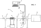
- a hot tube roll forming assembly 32 for shaping stock tubes 42 into transverse struts (such as the transverse strut 22 shown in Figure 2 and discussed above) is generally shown.
- the exemplary hot roll forming assembly 32 includes a plurality of tube drivers 34 , a heater 36 , a roll former 38, and a quenching bath 40 .
- the exemplary transverse strut 22 starts as a stock tube 42 having a diameter which is similar to the diameter of the cylindrical end sections 26 of the final transverse strut 22 to be produced.
- the tube 42 is preferably of one or more metals, such as various grades or alloys of steel, aluminum, iron, magnesium, etc.
- the tube 34 could be of any desirable type of formable material.
- the tube 42 is fed through the hot tube roll forming assembly 32 by the tube driver 34 or tube drivers 34 .
- the hot tube roll forming assembly 32 includes a plurality of tube drivers 34 , which are positioned between the other components of the hot tube roll forming assembly 32 .
- the hot roll forming assembly could include any desirable number of tube drivers 34 .
- the exemplary tube drivers 34 include a plurality of driven rollers 35 for urging the tube 42 in the axial direction.
- each tube driver 34 could be any desirable type of machine or robot for controllably guiding tubes 42 through the hot roll forming assembly 32 .
- the tube 42 is fed by the tube driver 34 through or adjacent to the heater 36 which heats the tube 42 to a predetermined annealing temperature for easier shaping and for preventing cracks during the shaping process, which is discussed in further detail below.
- the heater 36 is an induction heater 36 which is electrically connected to a power source 44 .
- the power source 44 is illustrated in the exemplary embodiment as being a battery. However, it should be appreciated that any desirable type of power source may be employed.
- the induction heater 36 heats the tube 42 through electromagnetic radiation, which has been found to be particularly efficient at heating metals and certain other materials to precise temperatures.
- any desirable type of heater or combination of heaters could be employed in the forming assembly 32 to heat the tube 42 to the predetermined annealing temperature.
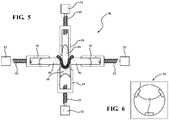
- the exemplary roll former 38 includes a plurality of forming wheels 46, 48, 50 arranged in a pattern. More precisely, the exemplary roll former 38 has an upper forming wheel 46 , a lower forming wheel 48 and a pair of side forming wheels 50 . Each of the forming wheels 46, 48, 50 is straddled by a fork-shaped member 51 which is operably coupled to a servo motor 52 via a ball screw 53 type of connection including a threaded rod. However, it should be appreciated that the forming wheels 46, 48, 50 could be coupled with the servo motors 52 through any desirable type of connection.
- the servo motors 52 are in electrical communication with a controller 54 which is configured to precisely adjust the positions of the forming wheels 46 , 48 , 50 relative to one another and relative to the tube 42 being fed through the hot tube roll forming assembly 32 .
- the controller 54 is shown as a desktop computer. However, it should be appreciated that any desirable type of controller could alternately be employed.
- the controller 54 activates the servo motors 52 to adjust the positions of the forming wheels 46 , 48 , 50 and urge them against the tube 42 .
- Electric servo motors 52 are preferred for controlling the positions of the forming wheels 46, 48, 50 because they are easily controlled and allow for quick and precise movements.
- any desirable type of actuators could be employed including, for example, hydraulic actuators or pneumatic actuators.
- the forming wheels 46, 48, 50 are spaced radially from the tube 42.
- the tube 42 is then fed a predetermined axial distance corresponding to the length of the cylindrical end sections 26 of the transverse strut 22 to be formed.
- the controller 54 (shown in Figure 3 ) operates the servo motors 52 to move each of the forming wheels 46, 48, 50 through a predetermined pattern with the forming wheels 46, 48, 50 engaging with the tube 42 to plastically deform the material of the tube 42 and shape it into a transverse strut 22 .
- the forming wheels 46, 48, 50 have moved to engage the transverse strut 22 , and the lower forming wheel 48 has been moved upwardly towards the upper forming wheel 46 to reduce the distance between the upper and lower forming wheels 46, 48 and give the middle section 28 of the transverse strut 22 the U-shaped profile described above.
- Controlled movements of the forming wheels 46, 48, 50 allow the roll former 38 to form both the transition sections 30 and the middle section 28 to very precise tolerances.
- the exemplary roll former 38 has been found to be able to form transverse struts 22 to dimensions accurate to 0.1 mm.
- the controller 54 may be programmed to operate the servo motors 52 to move the forming wheels 46, 48, 50 through different patterns thereby allowing for the formation of differently sized and shaped transverse struts 22 on the same hot tube roll forming assembly 32 with little or no adjustments to the other components of the hot tube roll forming assembly 32 .
- the hot tube roll forming assembly 32 may be used to form transverse struts 22 which are optimized for the suspensions of different types of vehicles or to form transverse struts 22 which give the same vehicle suspension different performance characteristics. It should be appreciated that the hot tube roll forming assembly 32 could include more than one set of forming wheels 46 , 48 , 50 , if desired.
- the exemplary assembly additionally includes a quenching bath 40 for quenching the heated transverse strut 22 after the roll forming process is completed.
- the entire transverse strut 22 could be simultaneously quenched, or only specific portions of the transverse strut 22 could be quenched to give the transverse strut 22 variable material characteristics.
- the fluid in the quenching bath 40 is preferably water; however, it should be appreciated that any desirable type of fluid could be employed. Quenching of the transverse strut 22 allows for the properties of the material to be controlled and also provides oxidation resistance to the transverse strut 22 .
- the hot tube roll forming assembly 32 also heat treats the material of the transverse strut 22 with little additional cost. This is beneficial because a separate heat treating process is not needed.
- each of the forming wheels 46, 48, 50 of the roll former 38 has a specific profile for forming its respective surface of the transverse strut 22 .
- the upper forming wheel 46 has a generally concave shape
- the lower forming wheel 48 has a generally convex shape
- each of the side forming wheels 50 has a frustoconical shape.
- the forming wheels 46, 48, 50 could take a wide range of other shapes to form differently shaped transverse struts 22 .
- the forming wheels 46 , 48 , 50 could also be removable and interchangeable for forming differently shaped transverse struts.
- the exemplary roll former 38 has four wheels 46 , 48 , 50 , it should be appreciated that the roll former 38 could include any desirable number of forming wheels.
- Another aspect of the present invention is a method of forming a transverse strut 22 for a twist beam axle assembly 20 from a tube 42 .
- An exemplary embodiment of the method includes the step of roll forming the tube 42 with a plurality of forming wheels 46, 48, 50 to shape the tube 42 .
- the method continues with adjusting the position of at least one of the forming wheels 46, 48, 50 in a radial direction to change the cross-sectional profile of the tube 42 to form a transverse strut 22 having a variable profile along its length.
- At least one of the forming wheels 46, 48, 50 is adjusted from a first position spaced from another of the forming wheels 46, 48, 50 by a predetermined distance to a second position spaced from the other of the forming wheels 46, 48, 50 by a lesser distance to form a pocket in the transverse strut 22 .
- the adjustments of the forming wheel or forming wheels 46, 48, 50 could be through, for example, a ball screw connection between the actuator(s) and the forming wheel(s) 46, 48, 50 .
- the forming wheels 46, 48, 50 may have similar or different shapes and, preferably, at least one of the forming wheels is non-cylindrical.
- the roll forming step forms a transverse strut 22 having a pair of end sections 26 with generally cylindrical shapes and a middle section 28 disposed between the end sections 26 with a pocket.
- the method may additionally include the step of heating the tube 42 before the step of roll forming the tube 42 and may also include the step of quenching at least a portion of the transverse strut 22 to give the material of the transverse strut 22 a desired microstructure.
- the heating of the tube 42 could be with, for example, an induction heater 36 .
Landscapes
- Engineering & Computer Science (AREA)
- Mechanical Engineering (AREA)
- Heat Treatment Of Articles (AREA)
- Bending Of Plates, Rods, And Pipes (AREA)
- Vehicle Body Suspensions (AREA)
- Shaping Of Tube Ends By Bending Or Straightening (AREA)
Claims (13)
- Rollformanordnung (32) zum Formen eines Rohres (42) in eine Querstrebe (22), umfassend:einen Heizer (36) zum Erwärmen des Rohres (42) auf eine vorbestimmte Temperatur;einen Rollformer (38), der eine Vielzahl von formenden Rädern (46, 48, 50) zum Verformen des Rohres (42) beinhaltet; undeinen Aktuator (52), der betreibbar mit mindestens einem der formenden Räder (46, 48, 50) des Rollformers (38) verbunden und dazu ausgelegt ist, das zugeordnete der formenden Räder (46, 48, 50) in einer radialen Richtung zu bewegen, um das Rohr (42) zu einer Querstrebe (22) zu verformen, die entlang der Länge der Querstrebe (22) eine variable Querschnittsform aufweist,gekennzeichnet dadurch, dassmindestens eines der formenden Räder (46, 48, 50) eine nicht zylindrische Form aufweist, um im Gebrauch die Querschnittsform des Rohres (42) entlang mindestens eines Teils des Rohres (42) zu einem allgemein U-förmigen Profil zu verändern.
- Rollformanordnung (32) nach Anspruch 1, die darüber hinaus ein Abschreckbad (40) zum Kühlen der Querstrebe (22) nach dem Formen durch den Rollformer (38) beinhaltet.
- Rollformanordnung (32) nach Anspruch 1, wobei der Heizer (36) ein Induktionsheizer ist.
- Rollformanordnung (32) nach Anspruch 1, wobei die Vielzahl von formenden Rädern (46, 48, 50) des Rollformers (38) ein oberes formendes Rad (46), ein unteres formendes Rad (48) und ein Paar von seitlichen formenden Rädern (50) beinhaltet.
- Rollformanordnung (32) nach Anspruch 1, wobei der Aktuator (52) über mindestens eine Kugelspindel (53) mit dem mindestens einen formenden Rad (46, 48, 50) betreibbar verbunden ist.
- Rollformanordnung (32) nach Anspruch 1, die ferner eine Steuerung (54) beinhaltet, die dazu ausgelegt ist, den Aktuator (52) zum Formen von Querstreben (22) mit unterschiedlichen Konfigurationen zu steuern.
- Verfahren zum Formen einer Querstrebe (22) aus einem Rohr (42), umfassend folgende Schritte:Rollformen des Rohres (42) mit einer Vielzahl von formenden Rädern (46, 48, 50), um dem Rohr (42) eine Form zu geben; undEinstellen der Position von mindestens einem der formenden Räder (46, 48, 50) in einer radialen Richtung mit einem Aktuator (52) während des Rollformens des Rohres (42), um die Querschnittsform des Rohres (42) entlang einer Länge des Rohres (42) zu verändern, um der Querstrebe (22) entlang der Länge ein variables Profil zu geben;dadurch gekennzeichnet, dassmindestens eines der formenden Räder (46, 48, 50) eine nicht zylindrische Form hat, um die Querschnittsform des Rohres (42) entlang mindestens eines Teils der Länge des Rohres (42) zu einem allgemein U-förmigen Profil zu formen.
- Verfahren zum Formen einer Querstrebe (22) nach Anspruch 7, das ferner den Schritt des Erwärmens des Rohres (42) auf eine vorbestimmte Temperatur vor dem Schritt des Rollformens des Rohres (42) umfasst.
- Verfahren zum Formen einer Querstrebe (22) nach Anspruch 8, das ferner den Schritt des Abschreckens der Querstrebe (22) nach dem Schritt des Rollformens des Rohres (42) umfasst.
- Verfahren zum Formen einer Querstrebe (22) nach Anspruch 7, wobei der Schritt des Einstellens ferner definiert ist als ein Einstellen der Position von mindestens einem rollformenden Rad (46, 48, 50) zu/von einer ersten Position, die von einem anderen der formenden Räder (46, 48, 50) um eine vorbestimmte Entfernung zu einer zweiten Position beanstandet ist, die von dem anderen der formenden Räder (46, 48, 50) um eine geringere Entfernung beanstandet ist, um eine Tasche in der Querstrebe (22) zu formen.
- Verfahren zum Formen einer Querstrebe (22) nach Anspruch 7, wobei der Aktuator (52) die Position von mindestens einem der formenden Räder (46, 48, 50) über eine Verbindung durch eine Kugelspindel (53) einstellt.
- Verfahren zum Formen einer Querstrebe (22) nach Anspruch 11, wobei das Erwärmen des Rohres (42) mit einem Induktionsheizer erfolgt.
- Verfahren zum Formen einer Querstrebe (22) nach Anspruch 7, wobei der Schritt des Rollformens eine Querstrebe (22) mit einem Paar von Endabschnitten (26) formt, die allgemein zylindrische Formen und eine Tasche aufweisen, die zwischen den Endabschnitten (26) angeordnet ist.
Applications Claiming Priority (2)
| Application Number | Priority Date | Filing Date | Title |
|---|---|---|---|
| US201261593377P | 2012-02-01 | 2012-02-01 | |
| PCT/US2013/024368 WO2013116666A1 (en) | 2012-02-01 | 2013-02-01 | Transverse strut and method of forming a transverse strut |
Publications (3)
| Publication Number | Publication Date |
|---|---|
| EP2809458A1 EP2809458A1 (de) | 2014-12-10 |
| EP2809458A4 EP2809458A4 (de) | 2015-07-01 |
| EP2809458B1 true EP2809458B1 (de) | 2019-05-15 |
Family
ID=48905879
Family Applications (1)
| Application Number | Title | Priority Date | Filing Date |
|---|---|---|---|
| EP13743645.7A Active EP2809458B1 (de) | 2012-02-01 | 2013-02-01 | Verfahren und vorrichtung zur herstellung einer querstrebe |
Country Status (11)
| Country | Link |
|---|---|
| US (1) | US9527120B2 (de) |
| EP (1) | EP2809458B1 (de) |
| JP (1) | JP6234380B2 (de) |
| KR (1) | KR20140121828A (de) |
| CN (1) | CN104093503A (de) |
| AU (1) | AU2013214918A1 (de) |
| BR (1) | BR112014017746A8 (de) |
| CA (1) | CA2859404C (de) |
| MX (1) | MX353405B (de) |
| RU (1) | RU2014131594A (de) |
| WO (1) | WO2013116666A1 (de) |
Families Citing this family (3)
| Publication number | Priority date | Publication date | Assignee | Title |
|---|---|---|---|---|
| CA2909707A1 (en) * | 2013-04-16 | 2014-10-23 | Magna International Inc. | Twist beam with joined inner and outer parts |
| FR3021563B1 (fr) * | 2014-06-03 | 2016-12-30 | Peugeot Citroen Automobiles Sa | Procede de fabrication de pieces par emboutissage et/ou hydroformage apres placement de bande(s) antifriction entre parois |
| DE112016003023T5 (de) * | 2015-06-30 | 2018-04-05 | Magna International Inc. | System zum kondensieren von material mit einem laser und verfahren dazu |
Family Cites Families (16)
| Publication number | Priority date | Publication date | Assignee | Title |
|---|---|---|---|---|
| JPS6167919U (de) * | 1984-10-08 | 1986-05-09 | ||
| JP2976834B2 (ja) * | 1995-01-23 | 1999-11-10 | 愛知製鋼株式会社 | 圧延チャンネルの製造方法 |
| US6349521B1 (en) * | 1999-06-18 | 2002-02-26 | Shape Corporation | Vehicle bumper beam with non-uniform cross section |
| US6523841B2 (en) * | 2000-05-31 | 2003-02-25 | Benteler Ag | Twist-beam axle for motor vehicles |
| JP4140462B2 (ja) * | 2003-06-27 | 2008-08-27 | トヨタ自動車株式会社 | トーションビーム式サスペンション装置 |
| FR2878786B1 (fr) * | 2004-12-08 | 2007-02-23 | Auto Chassis Internat Snc Snc | Essieu souple comprenant une traverse a section tropezoidale, traverse, vehicule et procede de fabrication correspondants |
| CN1718292A (zh) * | 2005-07-18 | 2006-01-11 | 莱芜钢铁集团有限公司 | 挂车轴管型钢及其加工方法 |
| FR2891480B1 (fr) * | 2005-10-04 | 2008-04-04 | Auto Chassis Internat Snc Snc | Outillage de fabrication d'une traverse a section fermee comprenant une matrice et/ou un poincon de longueur adaptable, et procede de fabrication correspondant. |
| JP2007237784A (ja) * | 2006-03-06 | 2007-09-20 | Futaba Industrial Co Ltd | トーションビーム式サスペンションの製造方法 |
| CN103101576B (zh) | 2007-04-04 | 2016-03-30 | 新日铁住金株式会社 | 前纵梁 |
| CN201068076Y (zh) * | 2007-06-19 | 2008-06-04 | 比亚迪股份有限公司 | 一种扭梁以及具有该扭梁的悬架 |
| ITTO20080521A1 (it) * | 2008-07-08 | 2010-01-08 | Sistemi Sospensioni Spa | Traversa per una sospensione posteriore a ponte torcente per autoveicolo e procedimento per la sua fabbricazione |
| US8317257B2 (en) * | 2008-09-29 | 2012-11-27 | Deakin University | Body for pneumatic vehicle |
| CA2644464C (en) * | 2008-10-17 | 2010-04-20 | Arcelormittal Tubular Products Canada Inc. | Twist-axle of variable wall thickness |
| EP2399685A4 (de) * | 2009-01-14 | 2015-12-23 | Nippon Steel & Sumitomo Metal Corp | Hohlglied und herstellungsvorrichtung und herstellungsverfahren dafür |
| JP5644254B2 (ja) * | 2010-08-19 | 2014-12-24 | Jfeスチール株式会社 | 異形断面管の製造方法及び装置 |
-
2013
- 2013-02-01 WO PCT/US2013/024368 patent/WO2013116666A1/en not_active Ceased
- 2013-02-01 JP JP2014555764A patent/JP6234380B2/ja not_active Expired - Fee Related
- 2013-02-01 AU AU2013214918A patent/AU2013214918A1/en not_active Abandoned
- 2013-02-01 CA CA2859404A patent/CA2859404C/en active Active
- 2013-02-01 CN CN201380007784.4A patent/CN104093503A/zh active Pending
- 2013-02-01 BR BR112014017746A patent/BR112014017746A8/pt not_active IP Right Cessation
- 2013-02-01 US US14/375,217 patent/US9527120B2/en active Active
- 2013-02-01 RU RU2014131594A patent/RU2014131594A/ru not_active Application Discontinuation
- 2013-02-01 EP EP13743645.7A patent/EP2809458B1/de active Active
- 2013-02-01 MX MX2014009294A patent/MX353405B/es active IP Right Grant
- 2013-02-01 KR KR1020147021282A patent/KR20140121828A/ko not_active Withdrawn
Non-Patent Citations (1)
| Title |
|---|
| None * |
Also Published As
| Publication number | Publication date |
|---|---|
| JP2015506873A (ja) | 2015-03-05 |
| US20140373589A1 (en) | 2014-12-25 |
| CA2859404C (en) | 2019-11-19 |
| US9527120B2 (en) | 2016-12-27 |
| AU2013214918A1 (en) | 2014-07-31 |
| CA2859404A1 (en) | 2013-08-08 |
| CN104093503A (zh) | 2014-10-08 |
| EP2809458A1 (de) | 2014-12-10 |
| MX353405B (es) | 2018-01-11 |
| JP6234380B2 (ja) | 2017-11-22 |
| RU2014131594A (ru) | 2016-03-20 |
| BR112014017746A2 (de) | 2017-06-20 |
| MX2014009294A (es) | 2014-09-11 |
| WO2013116666A1 (en) | 2013-08-08 |
| KR20140121828A (ko) | 2014-10-16 |
| BR112014017746A8 (pt) | 2017-07-11 |
| EP2809458A4 (de) | 2015-07-01 |
Similar Documents
| Publication | Publication Date | Title |
|---|---|---|
| EP0518929B1 (de) | Stabilisatorstange und verfahren und vorrichtung zur herstellung | |
| EP2517950B1 (de) | Frontpartieelement für eine Automobilkarosserie | |
| EP2345549B1 (de) | Armrohteil und herstellungsverfahren dafür | |
| EP2865548B1 (de) | Stabilisatorherstellungsverfahren und erwärmungsvorrichtung | |
| EP2446977B1 (de) | Verfahren zur Herstellung eines Rohrprofils | |
| CA2859404C (en) | Transverse strut and method of forming a transverse strut | |
| MX2011007474A (es) | Miembro hueco y un aparato y metodo para su fabricacion. | |
| JP4817911B2 (ja) | 中空管製品の鍛造成形方法 | |
| JP2021016891A (ja) | 中空屈曲部品の製造方法、中空屈曲部品の製造装置、及び中空屈曲部品 | |
| EP2675928B1 (de) | Herstellungsmethode für hochfeste stahlteile für den einsatz unter ermüdungsbeanspruchung | |
| EP1631402B1 (de) | Verfahren zur herstellung hohler bauelemente | |
| JP2021016890A (ja) | 中空屈曲部品の製造方法及び中空屈曲部品 | |
| EP3689490B1 (de) | Verfahren zur herstellung eines bauteils aus metall mittels innenhochdruckumformen | |
| JP2017170452A (ja) | 焼入れ鋼管部材及び焼入れ鋼管部材の製造方法 |
Legal Events
| Date | Code | Title | Description |
|---|---|---|---|
| PUAI | Public reference made under article 153(3) epc to a published international application that has entered the european phase |
Free format text: ORIGINAL CODE: 0009012 |
|
| 17P | Request for examination filed |
Effective date: 20140814 |
|
| AK | Designated contracting states |
Kind code of ref document: A1 Designated state(s): AL AT BE BG CH CY CZ DE DK EE ES FI FR GB GR HR HU IE IS IT LI LT LU LV MC MK MT NL NO PL PT RO RS SE SI SK SM TR |
|
| AX | Request for extension of the european patent |
Extension state: BA ME |
|
| DAX | Request for extension of the european patent (deleted) | ||
| RA4 | Supplementary search report drawn up and despatched (corrected) |
Effective date: 20150601 |
|
| RIC1 | Information provided on ipc code assigned before grant |
Ipc: B60G 21/05 20060101ALN20150526BHEP Ipc: B21B 1/08 20060101AFI20150526BHEP |
|
| 17Q | First examination report despatched |
Effective date: 20160712 |
|
| STAA | Information on the status of an ep patent application or granted ep patent |
Free format text: STATUS: EXAMINATION IS IN PROGRESS |
|
| REG | Reference to a national code |
Ref country code: DE Ref legal event code: R079 Ref document number: 602013055427 Country of ref document: DE Free format text: PREVIOUS MAIN CLASS: B21B0001080000 Ipc: B21D0005080000 |
|
| RIC1 | Information provided on ipc code assigned before grant |
Ipc: B60G 21/05 20060101ALN20181030BHEP Ipc: B21B 1/08 20060101ALI20181030BHEP Ipc: B21D 53/88 20060101ALI20181030BHEP Ipc: B21D 5/08 20060101AFI20181030BHEP |
|
| RIC1 | Information provided on ipc code assigned before grant |
Ipc: B21B 1/08 20060101ALI20181106BHEP Ipc: B21D 5/08 20060101AFI20181106BHEP Ipc: B21D 53/88 20060101ALI20181106BHEP Ipc: B60G 21/05 20060101ALN20181106BHEP |
|
| GRAP | Despatch of communication of intention to grant a patent |
Free format text: ORIGINAL CODE: EPIDOSNIGR1 |
|
| STAA | Information on the status of an ep patent application or granted ep patent |
Free format text: STATUS: GRANT OF PATENT IS INTENDED |
|
| INTG | Intention to grant announced |
Effective date: 20181220 |
|
| GRAS | Grant fee paid |
Free format text: ORIGINAL CODE: EPIDOSNIGR3 |
|
| GRAA | (expected) grant |
Free format text: ORIGINAL CODE: 0009210 |
|
| STAA | Information on the status of an ep patent application or granted ep patent |
Free format text: STATUS: THE PATENT HAS BEEN GRANTED |
|
| AK | Designated contracting states |
Kind code of ref document: B1 Designated state(s): AL AT BE BG CH CY CZ DE DK EE ES FI FR GB GR HR HU IE IS IT LI LT LU LV MC MK MT NL NO PL PT RO RS SE SI SK SM TR |
|
| REG | Reference to a national code |
Ref country code: CH Ref legal event code: EP Ref country code: GB Ref legal event code: FG4D |
|
| REG | Reference to a national code |
Ref country code: IE Ref legal event code: FG4D |
|
| REG | Reference to a national code |
Ref country code: DE Ref legal event code: R096 Ref document number: 602013055427 Country of ref document: DE |
|
| REG | Reference to a national code |
Ref country code: NL Ref legal event code: MP Effective date: 20190515 |
|
| REG | Reference to a national code |
Ref country code: LT Ref legal event code: MG4D |
|
| PG25 | Lapsed in a contracting state [announced via postgrant information from national office to epo] |
Ref country code: LT Free format text: LAPSE BECAUSE OF FAILURE TO SUBMIT A TRANSLATION OF THE DESCRIPTION OR TO PAY THE FEE WITHIN THE PRESCRIBED TIME-LIMIT Effective date: 20190515 Ref country code: HR Free format text: LAPSE BECAUSE OF FAILURE TO SUBMIT A TRANSLATION OF THE DESCRIPTION OR TO PAY THE FEE WITHIN THE PRESCRIBED TIME-LIMIT Effective date: 20190515 Ref country code: NL Free format text: LAPSE BECAUSE OF FAILURE TO SUBMIT A TRANSLATION OF THE DESCRIPTION OR TO PAY THE FEE WITHIN THE PRESCRIBED TIME-LIMIT Effective date: 20190515 Ref country code: SE Free format text: LAPSE BECAUSE OF FAILURE TO SUBMIT A TRANSLATION OF THE DESCRIPTION OR TO PAY THE FEE WITHIN THE PRESCRIBED TIME-LIMIT Effective date: 20190515 Ref country code: NO Free format text: LAPSE BECAUSE OF FAILURE TO SUBMIT A TRANSLATION OF THE DESCRIPTION OR TO PAY THE FEE WITHIN THE PRESCRIBED TIME-LIMIT Effective date: 20190815 Ref country code: FI Free format text: LAPSE BECAUSE OF FAILURE TO SUBMIT A TRANSLATION OF THE DESCRIPTION OR TO PAY THE FEE WITHIN THE PRESCRIBED TIME-LIMIT Effective date: 20190515 Ref country code: AL Free format text: LAPSE BECAUSE OF FAILURE TO SUBMIT A TRANSLATION OF THE DESCRIPTION OR TO PAY THE FEE WITHIN THE PRESCRIBED TIME-LIMIT Effective date: 20190515 Ref country code: PT Free format text: LAPSE BECAUSE OF FAILURE TO SUBMIT A TRANSLATION OF THE DESCRIPTION OR TO PAY THE FEE WITHIN THE PRESCRIBED TIME-LIMIT Effective date: 20190915 Ref country code: ES Free format text: LAPSE BECAUSE OF FAILURE TO SUBMIT A TRANSLATION OF THE DESCRIPTION OR TO PAY THE FEE WITHIN THE PRESCRIBED TIME-LIMIT Effective date: 20190515 |
|
| PG25 | Lapsed in a contracting state [announced via postgrant information from national office to epo] |
Ref country code: BG Free format text: LAPSE BECAUSE OF FAILURE TO SUBMIT A TRANSLATION OF THE DESCRIPTION OR TO PAY THE FEE WITHIN THE PRESCRIBED TIME-LIMIT Effective date: 20190815 Ref country code: LV Free format text: LAPSE BECAUSE OF FAILURE TO SUBMIT A TRANSLATION OF THE DESCRIPTION OR TO PAY THE FEE WITHIN THE PRESCRIBED TIME-LIMIT Effective date: 20190515 Ref country code: RS Free format text: LAPSE BECAUSE OF FAILURE TO SUBMIT A TRANSLATION OF THE DESCRIPTION OR TO PAY THE FEE WITHIN THE PRESCRIBED TIME-LIMIT Effective date: 20190515 Ref country code: GR Free format text: LAPSE BECAUSE OF FAILURE TO SUBMIT A TRANSLATION OF THE DESCRIPTION OR TO PAY THE FEE WITHIN THE PRESCRIBED TIME-LIMIT Effective date: 20190816 |
|
| REG | Reference to a national code |
Ref country code: AT Ref legal event code: MK05 Ref document number: 1132841 Country of ref document: AT Kind code of ref document: T Effective date: 20190515 |
|
| PG25 | Lapsed in a contracting state [announced via postgrant information from national office to epo] |
Ref country code: AT Free format text: LAPSE BECAUSE OF FAILURE TO SUBMIT A TRANSLATION OF THE DESCRIPTION OR TO PAY THE FEE WITHIN THE PRESCRIBED TIME-LIMIT Effective date: 20190515 Ref country code: DK Free format text: LAPSE BECAUSE OF FAILURE TO SUBMIT A TRANSLATION OF THE DESCRIPTION OR TO PAY THE FEE WITHIN THE PRESCRIBED TIME-LIMIT Effective date: 20190515 Ref country code: CZ Free format text: LAPSE BECAUSE OF FAILURE TO SUBMIT A TRANSLATION OF THE DESCRIPTION OR TO PAY THE FEE WITHIN THE PRESCRIBED TIME-LIMIT Effective date: 20190515 Ref country code: RO Free format text: LAPSE BECAUSE OF FAILURE TO SUBMIT A TRANSLATION OF THE DESCRIPTION OR TO PAY THE FEE WITHIN THE PRESCRIBED TIME-LIMIT Effective date: 20190515 Ref country code: EE Free format text: LAPSE BECAUSE OF FAILURE TO SUBMIT A TRANSLATION OF THE DESCRIPTION OR TO PAY THE FEE WITHIN THE PRESCRIBED TIME-LIMIT Effective date: 20190515 Ref country code: SK Free format text: LAPSE BECAUSE OF FAILURE TO SUBMIT A TRANSLATION OF THE DESCRIPTION OR TO PAY THE FEE WITHIN THE PRESCRIBED TIME-LIMIT Effective date: 20190515 |
|
| REG | Reference to a national code |
Ref country code: DE Ref legal event code: R097 Ref document number: 602013055427 Country of ref document: DE |
|
| PG25 | Lapsed in a contracting state [announced via postgrant information from national office to epo] |
Ref country code: SM Free format text: LAPSE BECAUSE OF FAILURE TO SUBMIT A TRANSLATION OF THE DESCRIPTION OR TO PAY THE FEE WITHIN THE PRESCRIBED TIME-LIMIT Effective date: 20190515 Ref country code: IT Free format text: LAPSE BECAUSE OF FAILURE TO SUBMIT A TRANSLATION OF THE DESCRIPTION OR TO PAY THE FEE WITHIN THE PRESCRIBED TIME-LIMIT Effective date: 20190515 |
|
| PLBE | No opposition filed within time limit |
Free format text: ORIGINAL CODE: 0009261 |
|
| STAA | Information on the status of an ep patent application or granted ep patent |
Free format text: STATUS: NO OPPOSITION FILED WITHIN TIME LIMIT |
|
| PG25 | Lapsed in a contracting state [announced via postgrant information from national office to epo] |
Ref country code: TR Free format text: LAPSE BECAUSE OF FAILURE TO SUBMIT A TRANSLATION OF THE DESCRIPTION OR TO PAY THE FEE WITHIN THE PRESCRIBED TIME-LIMIT Effective date: 20190515 |
|
| 26N | No opposition filed |
Effective date: 20200218 |
|
| PG25 | Lapsed in a contracting state [announced via postgrant information from national office to epo] |
Ref country code: PL Free format text: LAPSE BECAUSE OF FAILURE TO SUBMIT A TRANSLATION OF THE DESCRIPTION OR TO PAY THE FEE WITHIN THE PRESCRIBED TIME-LIMIT Effective date: 20190515 |
|
| PG25 | Lapsed in a contracting state [announced via postgrant information from national office to epo] |
Ref country code: SI Free format text: LAPSE BECAUSE OF FAILURE TO SUBMIT A TRANSLATION OF THE DESCRIPTION OR TO PAY THE FEE WITHIN THE PRESCRIBED TIME-LIMIT Effective date: 20190515 |
|
| REG | Reference to a national code |
Ref country code: CH Ref legal event code: PL |
|
| GBPC | Gb: european patent ceased through non-payment of renewal fee |
Effective date: 20200201 |
|
| REG | Reference to a national code |
Ref country code: BE Ref legal event code: MM Effective date: 20200229 |
|
| PG25 | Lapsed in a contracting state [announced via postgrant information from national office to epo] |
Ref country code: MC Free format text: LAPSE BECAUSE OF FAILURE TO SUBMIT A TRANSLATION OF THE DESCRIPTION OR TO PAY THE FEE WITHIN THE PRESCRIBED TIME-LIMIT Effective date: 20190515 Ref country code: LU Free format text: LAPSE BECAUSE OF NON-PAYMENT OF DUE FEES Effective date: 20200201 |
|
| PG25 | Lapsed in a contracting state [announced via postgrant information from national office to epo] |
Ref country code: LI Free format text: LAPSE BECAUSE OF NON-PAYMENT OF DUE FEES Effective date: 20200229 Ref country code: CH Free format text: LAPSE BECAUSE OF NON-PAYMENT OF DUE FEES Effective date: 20200229 |
|
| PG25 | Lapsed in a contracting state [announced via postgrant information from national office to epo] |
Ref country code: GB Free format text: LAPSE BECAUSE OF NON-PAYMENT OF DUE FEES Effective date: 20200201 Ref country code: FR Free format text: LAPSE BECAUSE OF NON-PAYMENT OF DUE FEES Effective date: 20200229 Ref country code: IE Free format text: LAPSE BECAUSE OF NON-PAYMENT OF DUE FEES Effective date: 20200201 |
|
| PG25 | Lapsed in a contracting state [announced via postgrant information from national office to epo] |
Ref country code: BE Free format text: LAPSE BECAUSE OF NON-PAYMENT OF DUE FEES Effective date: 20200229 |
|
| PG25 | Lapsed in a contracting state [announced via postgrant information from national office to epo] |
Ref country code: MT Free format text: LAPSE BECAUSE OF FAILURE TO SUBMIT A TRANSLATION OF THE DESCRIPTION OR TO PAY THE FEE WITHIN THE PRESCRIBED TIME-LIMIT Effective date: 20190515 Ref country code: CY Free format text: LAPSE BECAUSE OF FAILURE TO SUBMIT A TRANSLATION OF THE DESCRIPTION OR TO PAY THE FEE WITHIN THE PRESCRIBED TIME-LIMIT Effective date: 20190515 |
|
| PG25 | Lapsed in a contracting state [announced via postgrant information from national office to epo] |
Ref country code: MK Free format text: LAPSE BECAUSE OF FAILURE TO SUBMIT A TRANSLATION OF THE DESCRIPTION OR TO PAY THE FEE WITHIN THE PRESCRIBED TIME-LIMIT Effective date: 20190515 Ref country code: IS Free format text: LAPSE BECAUSE OF FAILURE TO SUBMIT A TRANSLATION OF THE DESCRIPTION OR TO PAY THE FEE WITHIN THE PRESCRIBED TIME-LIMIT Effective date: 20190915 |
|
| P01 | Opt-out of the competence of the unified patent court (upc) registered |
Effective date: 20230517 |
|
| REG | Reference to a national code |
Ref country code: DE Ref legal event code: R082 Ref document number: 602013055427 Country of ref document: DE Representative=s name: WITTE, WELLER & PARTNER PATENTANWAELTE MBB, DE |
|
| PGFP | Annual fee paid to national office [announced via postgrant information from national office to epo] |
Ref country code: DE Payment date: 20241210 Year of fee payment: 13 |