EP2809913B1 - Ensemble stator d'entrée centrale antigivrage pour turbine à gaz - Google Patents
Ensemble stator d'entrée centrale antigivrage pour turbine à gaz Download PDFInfo
- Publication number
- EP2809913B1 EP2809913B1 EP13775336.4A EP13775336A EP2809913B1 EP 2809913 B1 EP2809913 B1 EP 2809913B1 EP 13775336 A EP13775336 A EP 13775336A EP 2809913 B1 EP2809913 B1 EP 2809913B1
- Authority
- EP
- European Patent Office
- Prior art keywords
- gas turbine
- turbine engine
- set forth
- low pressure
- gear reduction
- Prior art date
- Legal status (The legal status is an assumption and is not a legal conclusion. Google has not performed a legal analysis and makes no representation as to the accuracy of the status listed.)
- Revoked
Links
Images

Classifications
-
- F—MECHANICAL ENGINEERING; LIGHTING; HEATING; WEAPONS; BLASTING
- F02—COMBUSTION ENGINES; HOT-GAS OR COMBUSTION-PRODUCT ENGINE PLANTS
- F02C—GAS-TURBINE PLANTS; AIR INTAKES FOR JET-PROPULSION PLANTS; CONTROLLING FUEL SUPPLY IN AIR-BREATHING JET-PROPULSION PLANTS
- F02C7/00—Features, components parts, details or accessories, not provided for in, or of interest apart form groups F02C1/00 - F02C6/00; Air intakes for jet-propulsion plants
- F02C7/04—Air intakes for gas-turbine plants or jet-propulsion plants
-
- F—MECHANICAL ENGINEERING; LIGHTING; HEATING; WEAPONS; BLASTING
- F02—COMBUSTION ENGINES; HOT-GAS OR COMBUSTION-PRODUCT ENGINE PLANTS
- F02C—GAS-TURBINE PLANTS; AIR INTAKES FOR JET-PROPULSION PLANTS; CONTROLLING FUEL SUPPLY IN AIR-BREATHING JET-PROPULSION PLANTS
- F02C7/00—Features, components parts, details or accessories, not provided for in, or of interest apart form groups F02C1/00 - F02C6/00; Air intakes for jet-propulsion plants
- F02C7/04—Air intakes for gas-turbine plants or jet-propulsion plants
- F02C7/047—Heating to prevent icing
-
- F—MECHANICAL ENGINEERING; LIGHTING; HEATING; WEAPONS; BLASTING
- F01—MACHINES OR ENGINES IN GENERAL; ENGINE PLANTS IN GENERAL; STEAM ENGINES
- F01D—NON-POSITIVE DISPLACEMENT MACHINES OR ENGINES, e.g. STEAM TURBINES
- F01D25/00—Component parts, details, or accessories, not provided for in, or of interest apart from, other groups
- F01D25/24—Casings; Casing parts, e.g. diaphragms, casing fastenings
-
- F—MECHANICAL ENGINEERING; LIGHTING; HEATING; WEAPONS; BLASTING
- F01—MACHINES OR ENGINES IN GENERAL; ENGINE PLANTS IN GENERAL; STEAM ENGINES
- F01D—NON-POSITIVE DISPLACEMENT MACHINES OR ENGINES, e.g. STEAM TURBINES
- F01D9/00—Stators
- F01D9/02—Nozzles; Nozzle boxes; Stator blades; Guide conduits, e.g. individual nozzles
- F01D9/04—Nozzles; Nozzle boxes; Stator blades; Guide conduits, e.g. individual nozzles forming ring or sector
-
- B—PERFORMING OPERATIONS; TRANSPORTING
- B64—AIRCRAFT; AVIATION; COSMONAUTICS
- B64D—EQUIPMENT FOR FITTING IN OR TO AIRCRAFT; FLIGHT SUITS; PARACHUTES; ARRANGEMENT OR MOUNTING OF POWER PLANTS OR PROPULSION TRANSMISSIONS IN AIRCRAFT
- B64D33/00—Arrangement in aircraft of power plant parts or auxiliaries not otherwise provided for
- B64D33/02—Arrangement in aircraft of power plant parts or auxiliaries not otherwise provided for of combustion air intakes
- B64D2033/0233—Arrangement in aircraft of power plant parts or auxiliaries not otherwise provided for of combustion air intakes comprising de-icing means
-
- F—MECHANICAL ENGINEERING; LIGHTING; HEATING; WEAPONS; BLASTING
- F01—MACHINES OR ENGINES IN GENERAL; ENGINE PLANTS IN GENERAL; STEAM ENGINES
- F01D—NON-POSITIVE DISPLACEMENT MACHINES OR ENGINES, e.g. STEAM TURBINES
- F01D25/00—Component parts, details, or accessories, not provided for in, or of interest apart from, other groups
- F01D25/02—De-icing means for engines having icing phenomena
-
- F—MECHANICAL ENGINEERING; LIGHTING; HEATING; WEAPONS; BLASTING
- F05—INDEXING SCHEMES RELATING TO ENGINES OR PUMPS IN VARIOUS SUBCLASSES OF CLASSES F01-F04
- F05D—INDEXING SCHEME FOR ASPECTS RELATING TO NON-POSITIVE-DISPLACEMENT MACHINES OR ENGINES, GAS-TURBINES OR JET-PROPULSION PLANTS
- F05D2220/00—Application
- F05D2220/30—Application in turbines
- F05D2220/32—Application in turbines in gas turbines
Definitions
- This application relates to a gas turbine engine, wherein the size and number of core inlet stator vanes at an upstream end of a compressor section are positioned to minimize icing concerns.
- Gas turbine engines typically include a fan delivering air into a compressor section as core flow, and also to a bypass path.
- the air entering the compressor section typically passes across inlet stator vanes, and towards a compressor rotor.
- the air is compressed in the compressor section, delivered into a combustion section, mixed with fuel and ignited. Products of this combustion pass downstream over turbine rotors, driving the rotors to rotate, and in turn drive the compressor and fan sections.
- a low pressure turbine drives a low pressure compressor
- a high pressure turbine drives a high pressure compressor
- the low pressure turbine typically also drives the fan blade through a low spool.
- the fan blade and low pressure compressor were constrained to rotate at the same speed as the low pressure turbine.
- ice may be passed downstream into the core flow.
- the ice may accumulate on an outer housing, known as a splitter, which defines an outer periphery of the core flow, and on the stator vanes. When the ice builds up, this is undesirable.
- the problem becomes particularly acute with a geared turbofan, as the core flow tends to be across a smaller cross-sectional area then in the prior systems.
- a prior art gas turbine engine having the features of the preamble to claim 1 is disclosed in " Pratt & Whitney PW8000" Jane's Aero-Engines (JAEng-issue7), March 2000, pg 510-512, XP008174951- by Bill Gunston . " The Weather of Atlantic Canada and Eastern Quebec, Graphic Area Forecast 34", 31 January 2002, pg 9-49, XP055214334 - by Bob Robichaud et al. discloses various effects of icing on an aircraft structure and methods for preventing such.
- the present invention provides a gas turbine engine in accordance with claim 1.
- the hydraulic diameter is greater than or equal to about 4.3cm (1.7 inches).
- the gear reduction is positioned inwardly of the inner core housing.
- a bypass ratio of the amount of air delivered into the bypass duct compared to the amount of air delivered into the core path is greater than about 6.
- the bypass ratio is greater than 10.
- the gear reduction has a gear reduction ratio greater than 2.3.
- the low pressure turbine has a pressure ratio that is greater than about 5:1.
- the gear reduction has a gear reduction ratio greater than 2.5.
- FIG. 1 schematically illustrates a gas turbine engine 20.
- the gas turbine engine 20 is disclosed herein as a two-spool turbofan that generally incorporates a fan section 22, a compressor section 24, a combustor section 26 and a turbine section 28.
- Alternative engines might include an augmentor section (not shown) among other systems or features.
- the fan section 22 drives air along a bypass flow path while the compressor section 24 drives air along a core flow path for compression and communication into the combustor section 26 then expansion through the turbine section 28.
- FIG. 1 schematically illustrates a gas turbine engine 20.
- the gas turbine engine 20 is disclosed herein as a two-spool turbofan that generally incorporates a fan section 22, a compressor section 24, a combustor section 26 and a turbine section 28.
- Alternative engines might include an augmentor section (not shown) among other systems or features.
- the fan section 22 drives air along a bypass flow path while the compressor section 24 drives air along a core flow path for compression and communication into the combustor section 26
- the engine 20 generally includes a low speed spool 30 and a high speed spool 32 mounted for rotation about an engine central longitudinal axis A relative to an engine static structure 36 via several bearing systems 38. It should be understood that various bearing systems 38 at various locations may alternatively or additionally be provided.
- the low speed spool 30 generally includes an inner shaft 40 that interconnects a fan 42, a low pressure compressor 44 and a low pressure turbine 46.
- the inner shaft 40 is connected to the fan 42 through a geared architecture 48 to drive the fan 42 at a lower speed than the low speed spool 30.
- the high speed spool 32 includes an outer shaft 50 that interconnects a high pressure compressor 52 and high pressure turbine 54.
- a combustor 56 is arranged between the high pressure compressor 52 and the high pressure turbine 54.
- a mid-turbine frame 57 of the engine static structure 36 is arranged generally between the high pressure turbine 54 and the low pressure turbine 46.
- the mid-turbine frame 57 further supports bearing systems 38 in the turbine section 28.
- the inner shaft 40 and the outer shaft 50 are concentric and rotate via bearing systems 38 about the engine central longitudinal axis A which is collinear with their longitudinal axes.
- the core airflow is compressed by the low pressure compressor 44 then the high pressure compressor 52, mixed and burned with fuel in the combustor 56, then expanded over the high pressure turbine 54 and low pressure turbine 46.
- the mid-turbine frame 57 includes airfoils 59 which are in the core airflow path.
- the turbines 46, 54 rotationally drive the respective low speed spool 30 and high speed spool 32 in response to the expansion.
- the engine 20 in one example is a high-bypass geared aircraft engine.
- the engine 20 bypass ratio is greater than about six, with an example embodiment being greater than ten
- the geared architecture 48 is an epicyclic gear train, such as a planetary gear system or other gear system, with a gear reduction ratio of greater than about 2.3
- the low pressure turbine 46 has a pressure ratio that is greater than about 5.
- the engine 20 bypass ratio is greater than about ten (10:1)
- the fan diameter is significantly larger than that of the low pressure compressor 44
- the low pressure turbine 46 has a pressure ratio that is greater than about 5:1.
- Low pressure turbine 46 pressure ratio is pressure measured prior to inlet of low pressure turbine 46 as related to the pressure at the outlet of the low pressure turbine 46 prior to an exhaust nozzle.
- the geared architecture 48 may be an epicycle gear train, such as a planetary gear system or other gear system, with a gear reduction ratio of greater than about 2.5:1. It should be understood, however, that the above parameters are only exemplary of one embodiment of a geared architecture engine and that the present invention is applicable to other gas turbine engines including direct drive turbofans.
- the fan section 22 of the engine 20 is designed for a particular flight condition -- typically cruise at about 0.8 Mach and about 10.7 km (35,000 feet).
- the flight condition of 0.8 Mach and 10.7 km (35,000 ft), with the engine at its best fuel consumption - also known as "bucket cruise Thrust Specific Fuel Consumption ('TSFC')" - is the industry standard parameter of lbm of fuel being burned divided by lbf of thrust the engine produces at that minimum point.
- "Low fan pressure ratio” is the pressure ratio across the fan blade alone, without a Fan Exit Guide Vane (“FEGV”) system.
- the low fan pressure ratio as disclosed herein according to one non-limiting embodiment is less than about 1.45.
- Low corrected fan tip speed is the actual fan tip speed in ft/sec divided by an industry standard temperature correction of [(Tambient deg R) / 518.7) ⁇ 0.5].
- the "Low corrected fan tip speed” as disclosed herein according to one non-limiting embodiment is less than about 351 m/s (1150 ft / second).
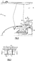
- Figure 2 shows a portion of the gas turbine engine 20.
- an outer housing known as a splitter 80 defines an outer periphery for the core flow path C.
- a row of stator vanes 82 is positioned at a forward end. Air from the fan blade is divided into the bypass flow path B, and into the core flow path C, as mentioned above.
- the gear reduction 48 is positioned inwardly of an inner housing 83.
- the spacing and number of stator vanes 82 is selected such that the total flow area A between the vanes 82 is selected to reduce the likelihood of icing.
- a pair of spaced vanes 82 are circumferentially spaced by area A.
- the area A is defined by a leading edge L of one vane 82, a leading edge L of an adjacent vane 82, the inner periphery O of the splitter 80, and the outer periphery I of the inner housing 83.
- a perimeter is defined by the sum of L, O, L and I.
- the hydraulic diameter is greater than or equal to about 3.8 cm (1.5 in). In preferred embodiments, it would be greater than or equal to about 4.3 cm (1.7 in).
- the hydraulic diameter can be calculated for a compressor module in a similar manner by measuring the leading edges and measuring the distances along the outer and inner boundaries of the flow area, even though the module is not mounted in a splitter or outward of an inner housing.
- Figure 3 shows a small circumferential segment, and it should be understood that the spacing is equal across the entire circumference.
Landscapes
- Engineering & Computer Science (AREA)
- Chemical & Material Sciences (AREA)
- Combustion & Propulsion (AREA)
- Mechanical Engineering (AREA)
- General Engineering & Computer Science (AREA)
- Structures Of Non-Positive Displacement Pumps (AREA)
- Retarders (AREA)
- Turbine Rotor Nozzle Sealing (AREA)
Claims (9)
- Turbine à gaz (20) comprenant :une soufflante (42) distribuant de l'air dans un trajet central (C) et dans un conduit de dilution en tant qu'air de dilution, ledit air dans ledit trajet central (C) atteignant un compresseur basse pression (44) puis un compresseur haute pression (52), l'air compressé par ledit compresseur haute pression (52) étant distribué dans une section de combustion (26) où il est mélangé avec du carburant et enflammé, les produits de la combustion passant en aval sur une turbine haute pression (54) puis une turbine basse pression (46),ladite turbine basse pression (46) entraînant ledit compresseur basse pression (44) en tant que corps à basse vitesse (30), et un démultiplicateur étant entraîné par ledit corps à basse vitesse (30) pour à son tour entraîner ladite soufflante (42) à une vitesse inférieure à celle dudit corps à basse vitesse (30), ledit démultiplicateur étant positionné vers l'intérieur d'un carter central interne (83) qui définit une périphérie interne (I) du trajet de central (C) ;un carter séparateur (80) définissant une périphérie externe (O) du trajet central (C), une pluralité d'aubes de stator d'entrée (82) s'étendant entre ledit séparateur (80) et ledit carter central interne (83), et une aire d'écoulement (A) étant présente entre des aubes de stator adjacentes (82), dans laquelle un diamètre hydraulique est défini par :
 caractérisée en ce quela pluralité d'aubes de stator d'entrée (82) sont équidistantes sur la totalité de la circonférence du carter séparateur (80), dans laquelle le nombre et l'espacement de la pluralité d'aubes (82) sont tels que le diamètre hydraulique entre chaque paire d'aubes espacées (82) est supérieur ou égal à environ 3,8 cm (1,5 pouce).
 - Turbine à gaz selon la revendication 1, dans laquelle ledit démultiplicateur est positionné vers l'intérieur dudit carter central interne (83).
- Turbine à gaz selon la revendication 2, dans laquelle ledit démultiplicateur a un rapport de démultiplication supérieur à 2,3.
- Turbine à gaz selon la revendication 3, dans laquelle ledit démultiplicateur a un rapport de démultiplication supérieur à 2,5.
- Turbine à gaz selon une quelconque revendication précédente, dans laquelle ledit diamètre hydraulique est supérieur ou égal à environ 4,3 cm (1,7 pouce).
- Turbine à gaz selon une quelconque revendication précédente, dans laquelle un rapport de dilution de la quantité d'air distribuée dans ledit conduit de dilution comparativement à la quantité d'air distribuée dans ledit trajet central (C) est supérieur à environ 6.
- Turbine à gaz selon la revendication 6, dans lequel ledit rapport de dilution est supérieur à 10.
- Turbine à gaz selon une quelconque revendication précédente, dans laquelle ladite soufflante (42) a un diamètre externe qui est supérieur à un diamètre externe des rotors dans ledit compresseur basse pression (44).
- Turbine à gaz selon une quelconque revendication précédente, dans laquelle ladite turbine basse pression (46) a un rapport de compression qui est supérieur à environ 5:1.
Applications Claiming Priority (3)
| Application Number | Priority Date | Filing Date | Title |
|---|---|---|---|
| US201261593083P | 2012-01-31 | 2012-01-31 | |
| US13/366,419 US9291064B2 (en) | 2012-01-31 | 2012-02-06 | Anti-icing core inlet stator assembly for a gas turbine engine |
| PCT/US2013/022398 WO2013154650A2 (fr) | 2012-01-31 | 2013-01-21 | Ensemble stator d'entrée centrale antigivrage pour turbine à gaz |
Publications (3)
| Publication Number | Publication Date |
|---|---|
| EP2809913A2 EP2809913A2 (fr) | 2014-12-10 |
| EP2809913A4 EP2809913A4 (fr) | 2015-10-28 |
| EP2809913B1 true EP2809913B1 (fr) | 2019-06-19 |
Family
ID=48869038
Family Applications (1)
| Application Number | Title | Priority Date | Filing Date |
|---|---|---|---|
| EP13775336.4A Revoked EP2809913B1 (fr) | 2012-01-31 | 2013-01-21 | Ensemble stator d'entrée centrale antigivrage pour turbine à gaz |
Country Status (4)
| Country | Link |
|---|---|
| US (2) | US9291064B2 (fr) |
| EP (1) | EP2809913B1 (fr) |
| SG (1) | SG11201403611TA (fr) |
| WO (1) | WO2013154650A2 (fr) |
Families Citing this family (6)
| Publication number | Priority date | Publication date | Assignee | Title |
|---|---|---|---|---|
| US9291064B2 (en) * | 2012-01-31 | 2016-03-22 | United Technologies Corporation | Anti-icing core inlet stator assembly for a gas turbine engine |
| US10309232B2 (en) * | 2012-02-29 | 2019-06-04 | United Technologies Corporation | Gas turbine engine with stage dependent material selection for blades and disk |
| US9976489B2 (en) | 2013-12-16 | 2018-05-22 | United Technologies Corporation | Gas turbine engine for long range aircraft |
| US9567907B2 (en) | 2015-02-24 | 2017-02-14 | General Electrical Company | Imaging assisted gas turbine anti-icing system |
| US11725525B2 (en) | 2022-01-19 | 2023-08-15 | Rolls-Royce North American Technologies Inc. | Engine section stator vane assembly with band stiffness features for turbine engines |
| US11920526B1 (en) * | 2022-08-12 | 2024-03-05 | Rtx Corporation | Inter-cooled preheat of steam injected turbine engine |
Family Cites Families (25)
| Publication number | Priority date | Publication date | Assignee | Title |
|---|---|---|---|---|
| GB1409589A (en) * | 1973-08-21 | 1975-10-08 | Atlas Copco Ab | Piston compressors |
| US3988798A (en) | 1975-07-16 | 1976-11-02 | Kratt Henry J | Self adjusting brush arm assembly |
| GB8630754D0 (en) * | 1986-12-23 | 1987-02-04 | Rolls Royce Plc | Turbofan gas turbine engine |
| US5267397A (en) * | 1991-06-27 | 1993-12-07 | Allied-Signal Inc. | Gas turbine engine module assembly |
| GB2259328B (en) * | 1991-09-03 | 1995-07-19 | Gen Electric | Gas turbine engine variable bleed pivotal flow splitter |
| GB2268978B (en) * | 1992-07-21 | 1995-11-08 | Rolls Royce Plc | Fan for a ducted fan gas turbine engine |
| FR2738283B1 (fr) * | 1995-08-30 | 1997-09-26 | Snecma | Agencement de turbomachine comprenant une grille d'aubes et un carter intermediaire |
| US6561760B2 (en) * | 2001-08-17 | 2003-05-13 | General Electric Company | Booster compressor deicer |
| US6990797B2 (en) | 2003-09-05 | 2006-01-31 | General Electric Company | Methods and apparatus for operating gas turbine engines |
| US7025563B2 (en) | 2003-12-19 | 2006-04-11 | United Technologies Corporation | Stator vane assembly for a gas turbine engine |
| EA009276B1 (ru) * | 2004-07-14 | 2007-12-28 | Флуор Текнолоджиз Корпорейшн | Конструкции и способы для выработки электроэнергии с регазификацией сжиженного природного газа |
| FR2894282A1 (fr) | 2005-12-05 | 2007-06-08 | Snecma Sa | Distributeur de turbine de turbomachine ameliore |
| US7694505B2 (en) | 2006-07-31 | 2010-04-13 | General Electric Company | Gas turbine engine assembly and method of assembling same |
| US20090260345A1 (en) | 2006-10-12 | 2009-10-22 | Zaffir Chaudhry | Fan variable area nozzle with adaptive structure |
| EP2074315A1 (fr) * | 2006-10-12 | 2009-07-01 | United Technologies Corporation | Contrôle de l'accumulation de givre sur un moteur d'avion et des composants statiques et rotatifs de nacelle |
| US7806652B2 (en) | 2007-04-10 | 2010-10-05 | United Technologies Corporation | Turbine engine variable stator vane |
| US7874161B2 (en) | 2007-07-25 | 2011-01-25 | Honeywell International Inc. | Compressor inlet guide vane flow based anti-ice formation control system and method |
| US8074440B2 (en) | 2007-08-23 | 2011-12-13 | United Technologies Corporation | Gas turbine engine with axial movable fan variable area nozzle |
| US9169779B2 (en) | 2007-10-09 | 2015-10-27 | United Technologies Corp. | Systems and methods for altering inlet airflow of gas turbine engines |
| US8049147B2 (en) | 2008-03-28 | 2011-11-01 | United Technologies Corporation | Engine inlet ice protection system with power control by zone |
| WO2010132086A1 (fr) * | 2009-05-12 | 2010-11-18 | Smith Fergus D | Dispositif et procédé de prévention et d'élimination d'accumulation de givre dans un compresseur de moteur à réaction par vibration de la vanne de prélèvement d'air par poussées asymétriques |
| JP5344165B2 (ja) | 2009-07-14 | 2013-11-20 | 株式会社Ihi | ガスタービンエンジン |
| GB0922285D0 (en) | 2009-12-22 | 2010-02-03 | Rolls Royce Plc | Hydrophobic surface |
| GB201009264D0 (en) | 2010-06-03 | 2010-07-21 | Rolls Royce Plc | Heat transfer arrangement for fluid washed surfaces |
| US9291064B2 (en) * | 2012-01-31 | 2016-03-22 | United Technologies Corporation | Anti-icing core inlet stator assembly for a gas turbine engine |
-
2012
- 2012-02-06 US US13/366,419 patent/US9291064B2/en active Active
-
2013
- 2013-01-21 EP EP13775336.4A patent/EP2809913B1/fr not_active Revoked
- 2013-01-21 WO PCT/US2013/022398 patent/WO2013154650A2/fr not_active Ceased
- 2013-01-21 SG SG11201403611TA patent/SG11201403611TA/en unknown
-
2015
- 2015-12-04 US US14/959,542 patent/US11391205B2/en active Active
Non-Patent Citations (1)
| Title |
|---|
| None * |
Also Published As
| Publication number | Publication date |
|---|---|
| US20130192197A1 (en) | 2013-08-01 |
| SG11201403611TA (en) | 2014-09-26 |
| EP2809913A4 (fr) | 2015-10-28 |
| US11391205B2 (en) | 2022-07-19 |
| US20160084106A1 (en) | 2016-03-24 |
| EP2809913A2 (fr) | 2014-12-10 |
| WO2013154650A2 (fr) | 2013-10-17 |
| WO2013154650A3 (fr) | 2014-05-22 |
| US9291064B2 (en) | 2016-03-22 |
Similar Documents
| Publication | Publication Date | Title |
|---|---|---|
| EP3036416B1 (fr) | Moteur à turbine à gaz à engrenages de poussée élevée | |
| US20160215730A1 (en) | Compressor area splits for geared turbofan | |
| US20150300264A1 (en) | Geared turbofan architecture for regional jet aircraft | |
| EP3054138B1 (fr) | Turbocompresseur avec turboréacteur à double flux à engrenage | |
| US11391205B2 (en) | Anti-icing core inlet stator assembly for a gas turbine engine | |
| EP3708792A1 (fr) | Moteur à turbine à gaz ayant une section basse pression haute vitesse et éléments de support de palier | |
| WO2015076961A1 (fr) | Tranchée de façonnage de paroi d'extrémité | |
| EP3059393A1 (fr) | Turbosoufflante à engrenage à rapport de transmission élevé et une capacité à haute température | |
| CA2886267C (fr) | Turboreacteur a engrenages a rapport de dilution et rapport de compresseur accrus obtenu grace a un faible nombre d'etages et de surfaces portantes totales | |
| EP3008291B1 (fr) | Aube de turbine à épaisseur de paroi non uniforme | |
| EP3045663B1 (fr) | Rotor de soufflante à aubage integral avec épaisseur côté pression sur le bord arrière | |
| EP2904217B1 (fr) | Aube directrice et moteur à turbine à gaz associé | |
| EP3165755A1 (fr) | Moteur à turbine à gaz ayant une section basse pression haute vitesse et éléments de support de palier | |
| EP2955325B1 (fr) | Turboréacteur à engrenages à rotor à aubage intégral | |
| EP3163033A1 (fr) | Moteur à turbine à gaz avec section de turbine basse pression à haute vitesse et éléments support de palier | |
| EP3163062A1 (fr) | Moteur à turbine à gaz ayant une section basse pression haute vitesse et éléments de support de palier | |
| EP3181861A1 (fr) | Turbine à gaz ayant une admission courte et fonction d'enlèvement de pale |
Legal Events
| Date | Code | Title | Description |
|---|---|---|---|
| PUAI | Public reference made under article 153(3) epc to a published international application that has entered the european phase |
Free format text: ORIGINAL CODE: 0009012 |
|
| 17P | Request for examination filed |
Effective date: 20140815 |
|
| AK | Designated contracting states |
Kind code of ref document: A2 Designated state(s): AL AT BE BG CH CY CZ DE DK EE ES FI FR GB GR HR HU IE IS IT LI LT LU LV MC MK MT NL NO PL PT RO RS SE SI SK SM TR |
|
| AX | Request for extension of the european patent |
Extension state: BA ME |
|
| DAX | Request for extension of the european patent (deleted) | ||
| RIC1 | Information provided on ipc code assigned before grant |
Ipc: F02C 7/04 20060101AFI20150812BHEP Ipc: F02C 7/047 20060101ALI20150812BHEP Ipc: F28D 15/02 20060101ALI20150812BHEP |
|
| A4 | Supplementary search report drawn up and despatched |
Effective date: 20150925 |
|
| RIC1 | Information provided on ipc code assigned before grant |
Ipc: F02C 7/04 20060101AFI20150921BHEP Ipc: F01D 9/04 20060101ALI20150921BHEP Ipc: F28D 15/02 20060101ALI20150921BHEP Ipc: F02C 7/047 20060101ALI20150921BHEP |
|
| 17Q | First examination report despatched |
Effective date: 20160527 |
|
| RAP1 | Party data changed (applicant data changed or rights of an application transferred) |
Owner name: UNITED TECHNOLOGIES CORPORATION |
|
| STAA | Information on the status of an ep patent application or granted ep patent |
Free format text: STATUS: EXAMINATION IS IN PROGRESS |
|
| REG | Reference to a national code |
Ref country code: DE Ref legal event code: R079 Ref document number: 602013056837 Country of ref document: DE Free format text: PREVIOUS MAIN CLASS: F02C0007040000 Ipc: F01D0017140000 |
|
| GRAP | Despatch of communication of intention to grant a patent |
Free format text: ORIGINAL CODE: EPIDOSNIGR1 |
|
| STAA | Information on the status of an ep patent application or granted ep patent |
Free format text: STATUS: GRANT OF PATENT IS INTENDED |
|
| RIC1 | Information provided on ipc code assigned before grant |
Ipc: F01D 25/02 20060101ALI20181130BHEP Ipc: F02C 7/047 20060101ALI20181130BHEP Ipc: F01D 25/24 20060101ALI20181130BHEP Ipc: F01D 9/04 20060101ALI20181130BHEP Ipc: F01D 17/14 20060101AFI20181130BHEP |
|
| INTG | Intention to grant announced |
Effective date: 20190104 |
|
| GRAS | Grant fee paid |
Free format text: ORIGINAL CODE: EPIDOSNIGR3 |
|
| GRAA | (expected) grant |
Free format text: ORIGINAL CODE: 0009210 |
|
| STAA | Information on the status of an ep patent application or granted ep patent |
Free format text: STATUS: THE PATENT HAS BEEN GRANTED |
|
| AK | Designated contracting states |
Kind code of ref document: B1 Designated state(s): AL AT BE BG CH CY CZ DE DK EE ES FI FR GB GR HR HU IE IS IT LI LT LU LV MC MK MT NL NO PL PT RO RS SE SI SK SM TR |
|
| REG | Reference to a national code |
Ref country code: GB Ref legal event code: FG4D |
|
| REG | Reference to a national code |
Ref country code: CH Ref legal event code: EP |
|
| REG | Reference to a national code |
Ref country code: IE Ref legal event code: FG4D |
|
| REG | Reference to a national code |
Ref country code: AT Ref legal event code: REF Ref document number: 1145777 Country of ref document: AT Kind code of ref document: T Effective date: 20190715 |
|
| REG | Reference to a national code |
Ref country code: DE Ref legal event code: R096 Ref document number: 602013056837 Country of ref document: DE |
|
| REG | Reference to a national code |
Ref country code: NL Ref legal event code: MP Effective date: 20190619 |
|
| PG25 | Lapsed in a contracting state [announced via postgrant information from national office to epo] |
Ref country code: SE Free format text: LAPSE BECAUSE OF FAILURE TO SUBMIT A TRANSLATION OF THE DESCRIPTION OR TO PAY THE FEE WITHIN THE PRESCRIBED TIME-LIMIT Effective date: 20190619 Ref country code: LT Free format text: LAPSE BECAUSE OF FAILURE TO SUBMIT A TRANSLATION OF THE DESCRIPTION OR TO PAY THE FEE WITHIN THE PRESCRIBED TIME-LIMIT Effective date: 20190619 Ref country code: FI Free format text: LAPSE BECAUSE OF FAILURE TO SUBMIT A TRANSLATION OF THE DESCRIPTION OR TO PAY THE FEE WITHIN THE PRESCRIBED TIME-LIMIT Effective date: 20190619 Ref country code: AL Free format text: LAPSE BECAUSE OF FAILURE TO SUBMIT A TRANSLATION OF THE DESCRIPTION OR TO PAY THE FEE WITHIN THE PRESCRIBED TIME-LIMIT Effective date: 20190619 Ref country code: NO Free format text: LAPSE BECAUSE OF FAILURE TO SUBMIT A TRANSLATION OF THE DESCRIPTION OR TO PAY THE FEE WITHIN THE PRESCRIBED TIME-LIMIT Effective date: 20190919 Ref country code: HR Free format text: LAPSE BECAUSE OF FAILURE TO SUBMIT A TRANSLATION OF THE DESCRIPTION OR TO PAY THE FEE WITHIN THE PRESCRIBED TIME-LIMIT Effective date: 20190619 |
|
| REG | Reference to a national code |
Ref country code: LT Ref legal event code: MG4D |
|
| PG25 | Lapsed in a contracting state [announced via postgrant information from national office to epo] |
Ref country code: BG Free format text: LAPSE BECAUSE OF FAILURE TO SUBMIT A TRANSLATION OF THE DESCRIPTION OR TO PAY THE FEE WITHIN THE PRESCRIBED TIME-LIMIT Effective date: 20190919 Ref country code: LV Free format text: LAPSE BECAUSE OF FAILURE TO SUBMIT A TRANSLATION OF THE DESCRIPTION OR TO PAY THE FEE WITHIN THE PRESCRIBED TIME-LIMIT Effective date: 20190619 Ref country code: GR Free format text: LAPSE BECAUSE OF FAILURE TO SUBMIT A TRANSLATION OF THE DESCRIPTION OR TO PAY THE FEE WITHIN THE PRESCRIBED TIME-LIMIT Effective date: 20190920 Ref country code: RS Free format text: LAPSE BECAUSE OF FAILURE TO SUBMIT A TRANSLATION OF THE DESCRIPTION OR TO PAY THE FEE WITHIN THE PRESCRIBED TIME-LIMIT Effective date: 20190619 |
|
| REG | Reference to a national code |
Ref country code: AT Ref legal event code: MK05 Ref document number: 1145777 Country of ref document: AT Kind code of ref document: T Effective date: 20190619 |
|
| PG25 | Lapsed in a contracting state [announced via postgrant information from national office to epo] |
Ref country code: EE Free format text: LAPSE BECAUSE OF FAILURE TO SUBMIT A TRANSLATION OF THE DESCRIPTION OR TO PAY THE FEE WITHIN THE PRESCRIBED TIME-LIMIT Effective date: 20190619 Ref country code: AT Free format text: LAPSE BECAUSE OF FAILURE TO SUBMIT A TRANSLATION OF THE DESCRIPTION OR TO PAY THE FEE WITHIN THE PRESCRIBED TIME-LIMIT Effective date: 20190619 Ref country code: PT Free format text: LAPSE BECAUSE OF FAILURE TO SUBMIT A TRANSLATION OF THE DESCRIPTION OR TO PAY THE FEE WITHIN THE PRESCRIBED TIME-LIMIT Effective date: 20191021 Ref country code: NL Free format text: LAPSE BECAUSE OF FAILURE TO SUBMIT A TRANSLATION OF THE DESCRIPTION OR TO PAY THE FEE WITHIN THE PRESCRIBED TIME-LIMIT Effective date: 20190619 Ref country code: CZ Free format text: LAPSE BECAUSE OF FAILURE TO SUBMIT A TRANSLATION OF THE DESCRIPTION OR TO PAY THE FEE WITHIN THE PRESCRIBED TIME-LIMIT Effective date: 20190619 Ref country code: RO Free format text: LAPSE BECAUSE OF FAILURE TO SUBMIT A TRANSLATION OF THE DESCRIPTION OR TO PAY THE FEE WITHIN THE PRESCRIBED TIME-LIMIT Effective date: 20190619 Ref country code: SK Free format text: LAPSE BECAUSE OF FAILURE TO SUBMIT A TRANSLATION OF THE DESCRIPTION OR TO PAY THE FEE WITHIN THE PRESCRIBED TIME-LIMIT Effective date: 20190619 |
|
| PG25 | Lapsed in a contracting state [announced via postgrant information from national office to epo] |
Ref country code: IT Free format text: LAPSE BECAUSE OF FAILURE TO SUBMIT A TRANSLATION OF THE DESCRIPTION OR TO PAY THE FEE WITHIN THE PRESCRIBED TIME-LIMIT Effective date: 20190619 Ref country code: IS Free format text: LAPSE BECAUSE OF FAILURE TO SUBMIT A TRANSLATION OF THE DESCRIPTION OR TO PAY THE FEE WITHIN THE PRESCRIBED TIME-LIMIT Effective date: 20191019 Ref country code: SM Free format text: LAPSE BECAUSE OF FAILURE TO SUBMIT A TRANSLATION OF THE DESCRIPTION OR TO PAY THE FEE WITHIN THE PRESCRIBED TIME-LIMIT Effective date: 20190619 Ref country code: ES Free format text: LAPSE BECAUSE OF FAILURE TO SUBMIT A TRANSLATION OF THE DESCRIPTION OR TO PAY THE FEE WITHIN THE PRESCRIBED TIME-LIMIT Effective date: 20190619 |
|
| REG | Reference to a national code |
Ref country code: DE Ref legal event code: R026 Ref document number: 602013056837 Country of ref document: DE |
|
| PLBI | Opposition filed |
Free format text: ORIGINAL CODE: 0009260 |
|
| PG25 | Lapsed in a contracting state [announced via postgrant information from national office to epo] |
Ref country code: TR Free format text: LAPSE BECAUSE OF FAILURE TO SUBMIT A TRANSLATION OF THE DESCRIPTION OR TO PAY THE FEE WITHIN THE PRESCRIBED TIME-LIMIT Effective date: 20190619 |
|
| 26 | Opposition filed |
Opponent name: SAFRAN AIRCRAFT ENGINES Effective date: 20200318 |
|
| PG25 | Lapsed in a contracting state [announced via postgrant information from national office to epo] |
Ref country code: DK Free format text: LAPSE BECAUSE OF FAILURE TO SUBMIT A TRANSLATION OF THE DESCRIPTION OR TO PAY THE FEE WITHIN THE PRESCRIBED TIME-LIMIT Effective date: 20190619 Ref country code: PL Free format text: LAPSE BECAUSE OF FAILURE TO SUBMIT A TRANSLATION OF THE DESCRIPTION OR TO PAY THE FEE WITHIN THE PRESCRIBED TIME-LIMIT Effective date: 20190619 |
|
| PG25 | Lapsed in a contracting state [announced via postgrant information from national office to epo] |
Ref country code: IS Free format text: LAPSE BECAUSE OF FAILURE TO SUBMIT A TRANSLATION OF THE DESCRIPTION OR TO PAY THE FEE WITHIN THE PRESCRIBED TIME-LIMIT Effective date: 20200224 |
|
| PLAX | Notice of opposition and request to file observation + time limit sent |
Free format text: ORIGINAL CODE: EPIDOSNOBS2 |
|
| PG2D | Information on lapse in contracting state deleted |
Ref country code: IS |
|
| PG25 | Lapsed in a contracting state [announced via postgrant information from national office to epo] |
Ref country code: SI Free format text: LAPSE BECAUSE OF FAILURE TO SUBMIT A TRANSLATION OF THE DESCRIPTION OR TO PAY THE FEE WITHIN THE PRESCRIBED TIME-LIMIT Effective date: 20190619 Ref country code: MC Free format text: LAPSE BECAUSE OF FAILURE TO SUBMIT A TRANSLATION OF THE DESCRIPTION OR TO PAY THE FEE WITHIN THE PRESCRIBED TIME-LIMIT Effective date: 20190619 |
|
| REG | Reference to a national code |
Ref country code: CH Ref legal event code: PL |
|
| REG | Reference to a national code |
Ref country code: BE Ref legal event code: MM Effective date: 20200131 |
|
| PLBB | Reply of patent proprietor to notice(s) of opposition received |
Free format text: ORIGINAL CODE: EPIDOSNOBS3 |
|
| PG25 | Lapsed in a contracting state [announced via postgrant information from national office to epo] |
Ref country code: LU Free format text: LAPSE BECAUSE OF NON-PAYMENT OF DUE FEES Effective date: 20200121 |
|
| PG25 | Lapsed in a contracting state [announced via postgrant information from national office to epo] |
Ref country code: CH Free format text: LAPSE BECAUSE OF NON-PAYMENT OF DUE FEES Effective date: 20200131 Ref country code: LI Free format text: LAPSE BECAUSE OF NON-PAYMENT OF DUE FEES Effective date: 20200131 Ref country code: BE Free format text: LAPSE BECAUSE OF NON-PAYMENT OF DUE FEES Effective date: 20200131 |
|
| PG25 | Lapsed in a contracting state [announced via postgrant information from national office to epo] |
Ref country code: IE Free format text: LAPSE BECAUSE OF NON-PAYMENT OF DUE FEES Effective date: 20200121 |
|
| RAP2 | Party data changed (patent owner data changed or rights of a patent transferred) |
Owner name: RAYTHEON TECHNOLOGIES CORPORATION |
|
| RDAF | Communication despatched that patent is revoked |
Free format text: ORIGINAL CODE: EPIDOSNREV1 |
|
| APBM | Appeal reference recorded |
Free format text: ORIGINAL CODE: EPIDOSNREFNO |
|
| APBP | Date of receipt of notice of appeal recorded |
Free format text: ORIGINAL CODE: EPIDOSNNOA2O |
|
| APAH | Appeal reference modified |
Free format text: ORIGINAL CODE: EPIDOSCREFNO |
|
| PG25 | Lapsed in a contracting state [announced via postgrant information from national office to epo] |
Ref country code: MT Free format text: LAPSE BECAUSE OF FAILURE TO SUBMIT A TRANSLATION OF THE DESCRIPTION OR TO PAY THE FEE WITHIN THE PRESCRIBED TIME-LIMIT Effective date: 20190619 Ref country code: CY Free format text: LAPSE BECAUSE OF FAILURE TO SUBMIT A TRANSLATION OF THE DESCRIPTION OR TO PAY THE FEE WITHIN THE PRESCRIBED TIME-LIMIT Effective date: 20190619 |
|
| APBQ | Date of receipt of statement of grounds of appeal recorded |
Free format text: ORIGINAL CODE: EPIDOSNNOA3O |
|
| PG25 | Lapsed in a contracting state [announced via postgrant information from national office to epo] |
Ref country code: MK Free format text: LAPSE BECAUSE OF FAILURE TO SUBMIT A TRANSLATION OF THE DESCRIPTION OR TO PAY THE FEE WITHIN THE PRESCRIBED TIME-LIMIT Effective date: 20190619 |
|
| REG | Reference to a national code |
Ref country code: DE Ref legal event code: R081 Ref document number: 602013056837 Country of ref document: DE Owner name: RAYTHEON TECHNOLOGIES CORPORATION (N.D.GES.D.S, US Free format text: FORMER OWNER: UNITED TECHNOLOGIES CORPORATION, FARMINGTON, CONN., US |
|
| APAH | Appeal reference modified |
Free format text: ORIGINAL CODE: EPIDOSCREFNO |
|
| P01 | Opt-out of the competence of the unified patent court (upc) registered |
Effective date: 20230520 |
|
| RAP4 | Party data changed (patent owner data changed or rights of a patent transferred) |
Owner name: RTX CORPORATION |
|
| PGFP | Annual fee paid to national office [announced via postgrant information from national office to epo] |
Ref country code: GB Payment date: 20231219 Year of fee payment: 12 |
|
| PGFP | Annual fee paid to national office [announced via postgrant information from national office to epo] |
Ref country code: FR Payment date: 20231219 Year of fee payment: 12 |
|
| REG | Reference to a national code |
Ref country code: DE Ref legal event code: R103 Ref document number: 602013056837 Country of ref document: DE Ref country code: DE Ref legal event code: R064 Ref document number: 602013056837 Country of ref document: DE |
|
| APBU | Appeal procedure closed |
Free format text: ORIGINAL CODE: EPIDOSNNOA9O |
|
| RDAG | Patent revoked |
Free format text: ORIGINAL CODE: 0009271 |
|
| STAA | Information on the status of an ep patent application or granted ep patent |
Free format text: STATUS: PATENT REVOKED |
|
| PGFP | Annual fee paid to national office [announced via postgrant information from national office to epo] |
Ref country code: DE Payment date: 20231219 Year of fee payment: 12 |
|
| REG | Reference to a national code |
Ref country code: CH Ref legal event code: PL |
|
| 27W | Patent revoked |
Effective date: 20240418 |
|
| GBPR | Gb: patent revoked under art. 102 of the ep convention designating the uk as contracting state |
Effective date: 20240418 |