EP2809915B1 - Moteur à turbine à gaz comportant un turboréacteur à double flux à engrenage et un système de gestion thermique d'huile - Google Patents
Moteur à turbine à gaz comportant un turboréacteur à double flux à engrenage et un système de gestion thermique d'huile Download PDFInfo
- Publication number
- EP2809915B1 EP2809915B1 EP13775295.2A EP13775295A EP2809915B1 EP 2809915 B1 EP2809915 B1 EP 2809915B1 EP 13775295 A EP13775295 A EP 13775295A EP 2809915 B1 EP2809915 B1 EP 2809915B1
- Authority
- EP
- European Patent Office
- Prior art keywords
- lubricant
- line
- gas turbine
- turbine engine
- oil
- Prior art date
- Legal status (The legal status is an assumption and is not a legal conclusion. Google has not performed a legal analysis and makes no representation as to the accuracy of the status listed.)
- Active
Links
Images

Classifications
-
- F—MECHANICAL ENGINEERING; LIGHTING; HEATING; WEAPONS; BLASTING
- F01—MACHINES OR ENGINES IN GENERAL; ENGINE PLANTS IN GENERAL; STEAM ENGINES
- F01D—NON-POSITIVE DISPLACEMENT MACHINES OR ENGINES, e.g. STEAM TURBINES
- F01D25/00—Component parts, details, or accessories, not provided for in, or of interest apart from, other groups
- F01D25/18—Lubricating arrangements
- F01D25/20—Lubricating arrangements using lubrication pumps
-
- F—MECHANICAL ENGINEERING; LIGHTING; HEATING; WEAPONS; BLASTING
- F01—MACHINES OR ENGINES IN GENERAL; ENGINE PLANTS IN GENERAL; STEAM ENGINES
- F01D—NON-POSITIVE DISPLACEMENT MACHINES OR ENGINES, e.g. STEAM TURBINES
- F01D25/00—Component parts, details, or accessories, not provided for in, or of interest apart from, other groups
- F01D25/18—Lubricating arrangements
-
- F—MECHANICAL ENGINEERING; LIGHTING; HEATING; WEAPONS; BLASTING
- F01—MACHINES OR ENGINES IN GENERAL; ENGINE PLANTS IN GENERAL; STEAM ENGINES
- F01M—LUBRICATING OF MACHINES OR ENGINES IN GENERAL; LUBRICATING INTERNAL COMBUSTION ENGINES; CRANKCASE VENTILATING
- F01M5/00—Heating, cooling, or controlling temperature of lubricant; Lubrication means facilitating engine starting
- F01M5/002—Cooling
-
- F—MECHANICAL ENGINEERING; LIGHTING; HEATING; WEAPONS; BLASTING
- F02—COMBUSTION ENGINES; HOT-GAS OR COMBUSTION-PRODUCT ENGINE PLANTS
- F02C—GAS-TURBINE PLANTS; AIR INTAKES FOR JET-PROPULSION PLANTS; CONTROLLING FUEL SUPPLY IN AIR-BREATHING JET-PROPULSION PLANTS
- F02C7/00—Features, components parts, details or accessories, not provided for in, or of interest apart form groups F02C1/00 - F02C6/00; Air intakes for jet-propulsion plants
- F02C7/06—Arrangements of bearings; Lubricating
-
- F—MECHANICAL ENGINEERING; LIGHTING; HEATING; WEAPONS; BLASTING
- F02—COMBUSTION ENGINES; HOT-GAS OR COMBUSTION-PRODUCT ENGINE PLANTS
- F02C—GAS-TURBINE PLANTS; AIR INTAKES FOR JET-PROPULSION PLANTS; CONTROLLING FUEL SUPPLY IN AIR-BREATHING JET-PROPULSION PLANTS
- F02C7/00—Features, components parts, details or accessories, not provided for in, or of interest apart form groups F02C1/00 - F02C6/00; Air intakes for jet-propulsion plants
- F02C7/12—Cooling of plants
- F02C7/14—Cooling of plants of fluids in the plant, e.g. lubricant or fuel
-
- F—MECHANICAL ENGINEERING; LIGHTING; HEATING; WEAPONS; BLASTING
- F02—COMBUSTION ENGINES; HOT-GAS OR COMBUSTION-PRODUCT ENGINE PLANTS
- F02K—JET-PROPULSION PLANTS
- F02K9/00—Rocket-engine plants, i.e. plants carrying both fuel and oxidant therefor; Control thereof
- F02K9/42—Rocket-engine plants, i.e. plants carrying both fuel and oxidant therefor; Control thereof using liquid or gaseous propellants
- F02K9/60—Constructional parts; Details not otherwise provided for
- F02K9/62—Combustion or thrust chambers
- F02K9/64—Combustion or thrust chambers having cooling arrangements
-
- F—MECHANICAL ENGINEERING; LIGHTING; HEATING; WEAPONS; BLASTING
- F05—INDEXING SCHEMES RELATING TO ENGINES OR PUMPS IN VARIOUS SUBCLASSES OF CLASSES F01-F04
- F05D—INDEXING SCHEME FOR ASPECTS RELATING TO NON-POSITIVE-DISPLACEMENT MACHINES OR ENGINES, GAS-TURBINES OR JET-PROPULSION PLANTS
- F05D2260/00—Function
- F05D2260/20—Heat transfer, e.g. cooling
- F05D2260/213—Heat transfer, e.g. cooling by the provision of a heat exchanger within the cooling circuit
-
- F—MECHANICAL ENGINEERING; LIGHTING; HEATING; WEAPONS; BLASTING
- F05—INDEXING SCHEMES RELATING TO ENGINES OR PUMPS IN VARIOUS SUBCLASSES OF CLASSES F01-F04
- F05D—INDEXING SCHEME FOR ASPECTS RELATING TO NON-POSITIVE-DISPLACEMENT MACHINES OR ENGINES, GAS-TURBINES OR JET-PROPULSION PLANTS
- F05D2260/00—Function
- F05D2260/40—Transmission of power
- F05D2260/403—Transmission of power through the shape of the drive components
- F05D2260/4031—Transmission of power through the shape of the drive components as in toothed gearing
- F05D2260/40311—Transmission of power through the shape of the drive components as in toothed gearing of the epicyclical, planetary or differential type
-
- Y—GENERAL TAGGING OF NEW TECHNOLOGICAL DEVELOPMENTS; GENERAL TAGGING OF CROSS-SECTIONAL TECHNOLOGIES SPANNING OVER SEVERAL SECTIONS OF THE IPC; TECHNICAL SUBJECTS COVERED BY FORMER USPC CROSS-REFERENCE ART COLLECTIONS [XRACs] AND DIGESTS
- Y02—TECHNOLOGIES OR APPLICATIONS FOR MITIGATION OR ADAPTATION AGAINST CLIMATE CHANGE
- Y02T—CLIMATE CHANGE MITIGATION TECHNOLOGIES RELATED TO TRANSPORTATION
- Y02T50/00—Aeronautics or air transport
- Y02T50/60—Efficient propulsion technologies, e.g. for aircraft
Definitions
- This application relates to an oil system for providing oil to a gear associated with a geared turbofan in a gas turbine engine.
- Gas turbine engines typically include a fan delivering air into a compressor section. Compressed air from the compressor section is delivered into a combustion section, mixed with fuel, and ignited. Products of this combustion pass downstream over turbine rotors which are driven to rotate.
- a low pressure turbine rotor drives a low pressure compressor, and traditionally has driven a fan at the same rate of speed.
- Oil management systems are known, and typically provide oil to engine bearings and other locations within the engine. As a result of gears being added to turbofan engines, additional components require cooling, thereby necessitating new cooling systems and methodologies.
- EP 1 923 542 A2 discloses a prior art lubricant supply system according to the preamble of claim 1.
- EP 1 930 557 A2 discloses a prior art turbine engine with integrated generator having shared lubrication system.
- US 4,020,632 discloses a prior art oil cooling system for a gas turbine engine.
- EP 2 587 024 A2 which is prior art under Art 54(3) EPC only, discloses interdependent lubrication systems.
- the lubricant in said cool line not being directed to the fuel/oil cooler may be directed to at least one other cooler through a second line.
- the at least one other cooler includes an air-to-oil cooler.
- the at least one other cooler also includes an oil-to-oil cooler at which oil from a generator exchanges heat with the oil in the second line.
- the cool line supplies lubricant to a journal bearing in a fan drive gear.
- a valve selectively supplies lubricant from the hot line to the fan drive gear when additional lubricant is necessary.
- the hot line intermixes with a portion of the oil in the cool line prior to being directed to the locations associated with an engine that are not intended to receive cooler lubricant.
- a gas turbine engine has a fan, a compressor section, including a low pressure compressor section and a high pressure compressor section, a combustor, and a turbine section including both a low pressure turbine and a high pressure turbine section.
- the low pressure turbine section drives the low pressure compressor section, and a fan drive gear is provided such that the low pressure turbine further drives the fan, with the fan and the low pressure compressor being driven at different rates.
- the gas turbine engine includes a lubricant system according to the previous embodiments.
- the locations in the engine that are not intended to receive cooler lubricant include bearings associated with at least the turbine section.
- the low pressure turbine has a pressure ratio greater than about 5:1.
- a gear reduction ratio of the fan drive gear is greater than about 2.3.
- a diameter of the fan is significantly larger than a diameter of the low pressure compressor.
- the lubricant in the hot line is intermixed with a portion of the lubricant from the cool line prior to being delivered to the locations in the gas turbine engine that are not intended to receive cooler lubricant.
- the lubricant in the hot line is intermixed with a portion of the lubricant in the cool line prior to being delivered to the bearings.
- FIG. 1 schematically illustrates a gas turbine engine 20.
- the gas turbine engine 20 is disclosed herein as a two-spool turbofan that generally incorporates a fan section 22, a compressor section 24, a combustor section 26 and a turbine section 28.
- Alternative engines might include an augmenter section (not shown) among other systems or features.
- the fan section 22 drives air along a bypass flowpath B while the compressor section 24 drives air along a core flowpath C for compression and communication into the combustor section 26 then expansion through the turbine section 28.
- a turbofan gas turbine engine in the disclosed non-limiting embodiment, it should be understood that the concepts described herein are not limited to use with turbofans as the teachings may be applied to other types of turbine engines including three-spool architectures.
- the engine 20 generally includes a low speed spool 30 and a high speed spool 32 mounted for rotation about an engine central longitudinal axis A relative to an engine static structure 36 via several bearing systems 38. It should be understood that various bearing systems 38 at various locations may alternatively or additionally be provided.
- the low speed spool 30 generally includes an inner shaft 40 that interconnects a fan 42, a low pressure compressor 44 and a low pressure turbine 46.
- the inner shaft 40 is connected to the fan 42 through a geared architecture 48 (shown schematically) to drive the fan 42 at a lower speed than the low speed spool 30.
- the high speed spool 32 includes an outer shaft 50 that interconnects a high pressure compressor 52 and high pressure turbine 54.
- a combustor 56 is arranged between the high pressure compressor 52 and the high pressure turbine 54.
- a mid-turbine frame 57 of the engine static structure 36 is arranged generally between the high pressure turbine 54 and the low pressure turbine 46.
- the mid-turbine frame 57 further supports bearing systems 38 in the turbine section 28.
- the inner shaft 40 and the outer shaft 50 are concentric and rotate via bearing systems 38 about the engine central longitudinal axis A which is collinear with their longitudinal axes.
- the core airflow C is compressed by the low pressure compressor 44 then the high pressure compressor 52, mixed and burned with fuel in the combustor 56, then expanded over the high pressure turbine 54 and low pressure turbine 46.
- the mid-turbine frame 57 includes airfoils 59 which are in the core airflow path.
- the turbines 46, 54 rotationally drive the respective low speed spool 30 and high speed spool 32 in response to the previously mentioned expansion.
- the engine 20 in one example is a high-bypass geared aircraft engine.
- the engine 20 bypass ratio is greater than about six (6), with an example embodiment being greater than ten (10)
- the geared architecture 48 is an epicyclic gear train, such as a planetary gear system or other gear system, with a gear reduction ratio of greater than about 2.3
- the low pressure turbine 46 has a pressure ratio that is greater than about 5.
- the engine 20 bypass ratio is greater than about ten (10:1)
- the fan diameter is significantly larger than that of the low pressure compressor 44
- the low pressure turbine 46 has a pressure ratio that is greater than about 5:1.
- Low pressure turbine 46 pressure ratio is pressure measured prior to inlet of low pressure turbine 46 as related to the pressure at the outlet of the low pressure turbine 46 prior to an exhaust nozzle.
- the geared architecture 48 may be an epicycle gear train, such as a planetary gear system or other gear system, with a gear reduction ratio of greater than about 2.5:1. It should be understood, however, that the above parameters are only exemplary of one embodiment of a geared architecture engine and that the present invention is applicable to other gas turbine engines including direct drive turbofans.
- the fan section 22 of the engine 20 is designed for a particular flight condition -- typically cruise at about 0.8 Mach and about 35,000 feet (10,668 m).
- the flight condition of 0.8 Mach and 35,000 ft (10,668 m), with the engine at its best fuel consumption - also known as "bucket cruise Thrust Specific Fuel Consumption ('TSFC')" - is the industry standard parameter of lbm of fuel being burned divided by lbf of thrust the engine produces at that minimum point.
- "Low fan pressure ratio” is the pressure ratio across the fan blade alone, without a Fan Exit Guide Vane (“FEGV”) system.
- the low fan pressure ratio as disclosed herein according to one non-limiting embodiment is less than about 1.45.
- the "Low corrected fan tip speed” as disclosed herein according to one non-limiting embodiment is less than about 1150 ft / second (350.52 m/s).
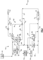
- FIG 2 is an oil management system for the gas turbine engine system of Figure 1 .
- the oil management system 140 is utilized in association with a fuel system 143, and a variable frequency generator 160 and its oil cooling system circuit 162.
- the fuel is heated, and cools a lubricant, as will be explained below.
- a main fuel pump 146 drives the fuel into further fuel lines 243 and then into nozzles 148 in a combustor, such as combustor 26 as shown in Figure 1 . It is known in the art to heat the fuel to improve the efficiency of the overall engine.
- the fuel/oil cooler 144 provides this function.
- variable frequency generator 160 is driven by turbine rotors to generate electricity for various uses on an aircraft.
- oil cooling system circuit 162 the oil passes through an oil-to-oil cooler 164, and may also pass through an air-to-oil cooler 66 before returning to the variable frequency generator 160.
- An oil supply system 150 includes a main oil pump 70 taking oil from a main oil tank 72.
- the terms “oil” and “lubricant” are used interchangeably in this application and cover a fluid used to lubricate surfaces subject to relative rotation.
- the oil is delivered through a downstream line 73, and split between two lines 74 and 75.
- Line 74 is sent directly to line 86 without cooling.
- a modulating valve 76 is controlled to achieve a desired fuel temperature.
- a sensor 300 may send a signal to a control regarding a sensed temperature of the fuel downstream of the fuel oil cooler 144.
- the valve 76 routes the volume of oil between line 78 and 80 to achieve the desired temperature of the fuel.
- the oil passing to line 78 passes through the fuel/oil cooler 144 and heats the fuel.
- the oil is cooled before returning to a common downstream line 82.
- the downstream line 82 could be called a "cool” oil line, as the oil will be cooler than the oil in "hot” line 74 which has not been cooled in any heat exchanger.
- line 75 is seen as part of the "cool” line even though the lubricant has yet to be cooled.
- the oil directed by the valve 76 into line 80 passes through an air-to-oil cooler at 68 which is exposed to air which is cooler than the oil in line 80, and which cools the oil. Downstream of the air-to-oil cooler 68, the oil passes through the oil-to-oil cooler 164, and may actually be somewhat heated by cooling the oil for the variable frequency generator. Still, the oil reaching line 82 downstream of the oil-to-oil cooler 164 will be significantly cooler than the oil in line 74. Some of the oil in line 82 is directed into a line 84, to a journal bearing 152, and to the fan drive gears 154. Thus, cooler oil is supplied to the bearing 152 and gears 154 than is supplied from the line 74.
- a line 86 branches off of the "cool" line 82 at or near the point at which "cool” line 84 breaks away to go to the journal bearing 152 and the gears 154.
- the lubricant in line 86 mixes with the lubricant in "hot” line 74, but downstream of the branch line 84.
- bearings 90 as shown in Figure 2 may equate to the several locations of bearings 38 as shown in Figure 1 .
- the journal bearing 152 and the fan drive gears 154 would be part of the geared architecture 48 as shown in Figure 1 .
- splitting the oil, and cooling the oil to be directed to the bearings 152 and/or gears 154 provides cooler oil to those locations, while still allowing the hotter oil to be directed to locations that do not need cooler oil.
- a valve 92 can selectively direct additional oil to the gears 154 if additional oil is necessary, such as at high power times. At other times, the valve 92 may direct lubricant through line 94 back to a return line 95 leading back to the oil tank 72.
- the overall configuration thus results in an oil supply system which directs hotter oil to the locations which do not need cooler oil, but which also cools oil to be directed to areas associated with the fan drive gear.
Landscapes
- Engineering & Computer Science (AREA)
- Mechanical Engineering (AREA)
- General Engineering & Computer Science (AREA)
- Chemical & Material Sciences (AREA)
- Combustion & Propulsion (AREA)
- General Details Of Gearings (AREA)
Claims (15)
- Système de fourniture de lubrifiant (150) d'un moteur à turbine à gaz (20), comprenant :
une pompe à lubrifiant (70) délivrant du lubrifiant à une conduite de sortie (73), ladite conduite de sortie (73) se divisant en au moins une conduite chaude (74) et une conduite froide (75), ladite conduite chaude (74) étant dirigée principalement vers des emplacements associés à un moteur qui ne sont pas destinés à recevoir du lubrifiant plus froid, et ladite conduite froide (75) étant dirigée à travers un ou plusieurs échangeurs thermiques (68, 144, 164) dans lesquels le lubrifiant est refroidi, puis ladite conduite froide (75) étant acheminée vers un engrenage d'entraînement de ventilateur (154) pour un moteur à turbine à gaz associé, caractérisé en ce que :
une vanne (76) est positionnée sur ladite conduite froide et divise ladite conduite froide en deux conduites (78, 80), une première conduite (78) étant dirigée à travers un refroidisseur carburant/huile (144) dans lequel le lubrifiant sera refroidi par le carburant menant à une section de combustion pour le moteur à turbine à gaz. - Système selon la revendication 1, dans lequel le lubrifiant dans ladite conduite froide (75) n'étant pas dirigé vers le refroidisseur carburant/huile (144) est dirigé vers au moins un autre refroidisseur à travers une seconde conduite.
- Système (150) selon la revendication 2, dans lequel ledit au moins un autre refroidisseur comprend un refroidisseur air-huile (68).
- Système (150) selon la revendication 3, dans lequel ledit au moins un autre refroidisseur comprend également un refroidisseur huile-huile (164) au niveau duquel l'huile provenant d'un générateur (160) échange la chaleur avec l'huile dans ladite seconde conduite (80).
- Système (150) selon une quelconque revendication précédente, dans lequel ladite conduite froide (75) fournit du lubrifiant à un palier lisse (152) dans un engrenage d'entraînement de ventilateur.
- Système (150) selon une quelconque revendication précédente, dans lequel une vanne (92) fournit de manière sélective du lubrifiant de ladite conduite chaude (74) à l'engrenage d'entraînement de ventilateur (154) lorsque du lubrifiant supplémentaire est nécessaire.
- Système (150) selon une quelconque revendication précédente, dans lequel ladite conduite chaude (74) se mélange avec une partie du lubrifiant dans la conduite froide (75) avant d'être dirigée vers les emplacements associés à un moteur qui ne sont pas destinés à recevoir un lubrifiant plus froid.
- Moteur à turbine à gaz (20), comprenant :un ventilateur (22), une section de compresseur (24) comprenant une section de compresseur basse pression (44) et une section de compresseur haute pression (52) ;une section de combustion (26) ;une section de turbine (28) comprenant à la fois une turbine basse pression (46) et une section de turbine haute pression (54), et ladite section de turbine basse pression (46) entraînant ladite section de compresseur basse pression (44), et un engrenage d'entraînement de ventilateur (48) prévu de sorte que ladite turbine basse pression (46) entraîne en outre ledit ventilateur (22), ledit ventilateur (22) et ledit compresseur basse pression (44) étant entraînés à des vitesses différentes ; etun système de fourniture de lubrifiant (150) selon une quelconque revendication précédente.
- Moteur à turbine à gaz (20) selon la revendication 8, dans lequel lesdits emplacements dans le moteur (20) qui ne sont pas destinés à recevoir un lubrifiant plus froid comprennent des paliers (90) associés à au moins la section de turbine.
- Moteur à turbine à gaz (20) selon la revendication 8 ou 9, dans lequel ladite turbine basse pression (46) a un rapport de pression supérieur à 5:1.
- Moteur à turbine à gaz (20) selon la revendication 8, 9 ou 10, dans lequel un rapport de démultiplication dudit engrenage d'entraînement de ventilateur (48) est supérieur à 2,3.
- Moteur à turbine à gaz (20) selon l'une quelconque des revendications 8 à 11, dans lequel un diamètre dudit ventilateur (22) est sensiblement plus grand qu'un diamètre dudit compresseur basse pression (44).
- Moteur à turbine à gaz (20) selon l'une quelconque des revendications 8 à 12, dans lequel le lubrifiant dans la conduite chaude (74) est mélangé avec une partie du lubrifiant provenant de la conduite froide (75) avant d'être délivré auxdits emplacements dans le moteur à turbine à gaz (20) qui ne sont pas destinés à recevoir un lubrifiant plus froid.
- Procédé de gestion de fourniture de lubrifiant pour un moteur à turbine à gaz (20) comprenant les étapes de :
déplacement d'un lubrifiant d'une pompe à lubrifiant (70) dans une conduite de sortie (73), et division de la conduite de sortie (73) en une conduite froide (75) qui est délivrée dans au moins un échangeur thermique (68, 144, 164) pour refroidir le lubrifiant, et le lubrifiant refroidi étant ensuite délivré à un engrenage d'entraînement de ventilateur (154) qui entraîne un ventilateur associé au moteur à turbine à gaz ; et fourniture du lubrifiant depuis une conduite chaude (74) qui ne passe pas à travers ledit au moins un échangeur de chaleur vers des paliers (90) associés à au moins une section de turbine dans le moteur à turbine à gaz, caractérisé en ce que :
une vanne (76) est positionnée sur ladite conduite froide et divise ladite conduite froide en deux conduites (78, 80), une première conduite (78) étant dirigée à travers un refroidisseur carburant/huile (144) dans lequel le lubrifiant sera refroidi par le carburant menant à une section de combustion pour le moteur à turbine à gaz. - Procédé selon la revendication 14, dans lequel le lubrifiant dans la conduite chaude (74) est mélangé avec une partie du lubrifiant dans la conduite froide (75) avant d'être délivré auxdits paliers (90).
Applications Claiming Priority (2)
| Application Number | Priority Date | Filing Date | Title |
|---|---|---|---|
| US13/361,997 US8443582B1 (en) | 2012-01-31 | 2012-01-31 | Gas turbine engine with geared turbofan and oil thermal management system |
| PCT/US2013/021794 WO2013154637A1 (fr) | 2012-01-31 | 2013-01-17 | Moteur à turbine à gaz comportant un turboréacteur à double flux à engrenage et un système de gestion thermique d'huile |
Publications (3)
| Publication Number | Publication Date |
|---|---|
| EP2809915A1 EP2809915A1 (fr) | 2014-12-10 |
| EP2809915A4 EP2809915A4 (fr) | 2015-10-14 |
| EP2809915B1 true EP2809915B1 (fr) | 2019-08-07 |
Family
ID=48365225
Family Applications (1)
| Application Number | Title | Priority Date | Filing Date |
|---|---|---|---|
| EP13775295.2A Active EP2809915B1 (fr) | 2012-01-31 | 2013-01-17 | Moteur à turbine à gaz comportant un turboréacteur à double flux à engrenage et un système de gestion thermique d'huile |
Country Status (3)
| Country | Link |
|---|---|
| US (3) | US8443582B1 (fr) |
| EP (1) | EP2809915B1 (fr) |
| WO (1) | WO2013154637A1 (fr) |
Families Citing this family (33)
| Publication number | Priority date | Publication date | Assignee | Title |
|---|---|---|---|---|
| US8443582B1 (en) * | 2012-01-31 | 2013-05-21 | United Technologies Corporation | Gas turbine engine with geared turbofan and oil thermal management system |
| WO2014200587A2 (fr) * | 2013-01-21 | 2014-12-18 | United Technologies Corporation | Système d'augmentation de l'écoulement d'air de refroidisseur d'huile par air |
| WO2014151356A1 (fr) | 2013-03-15 | 2014-09-25 | United Technologies Corporation | Système et méthode de gestion thermique de moteur à turbine à architecture à engrenages |
| WO2015047885A1 (fr) | 2013-09-26 | 2015-04-02 | United Technologies Corporation | Commande d'écoulement de lubrifiant dans une boîte d'engrenages épicycloîdaux |
| FR3020658B1 (fr) * | 2014-04-30 | 2020-05-15 | Safran Aircraft Engines | Capot de recuperation d'huile de lubrification pour un equipement de turbomachine |
| US9869190B2 (en) | 2014-05-30 | 2018-01-16 | General Electric Company | Variable-pitch rotor with remote counterweights |
| US10072510B2 (en) | 2014-11-21 | 2018-09-11 | General Electric Company | Variable pitch fan for gas turbine engine and method of assembling the same |
| US9752507B2 (en) | 2015-02-10 | 2017-09-05 | United Technologies Corporation | Aircraft system with fuel-to-fuel heat exchanger |
| US10100653B2 (en) | 2015-10-08 | 2018-10-16 | General Electric Company | Variable pitch fan blade retention system |
| US20180340471A1 (en) * | 2015-11-03 | 2018-11-29 | Eaton Corporation | Pump bearing flow control |
| GB201605270D0 (en) | 2016-03-30 | 2016-05-11 | Rolls Royce Plc | A fuel and oil system |
| US10345830B2 (en) * | 2016-05-03 | 2019-07-09 | United Technologies Corporation | Thermal management system control and heat exchanger life extension |
| US10308366B2 (en) * | 2016-08-22 | 2019-06-04 | General Electric Company | Embedded electric machine |
| US10544717B2 (en) | 2016-09-07 | 2020-01-28 | Pratt & Whitney Canada Corp. | Shared oil system arrangement for an engine component and a generator |
| EP3336320B1 (fr) * | 2016-12-14 | 2020-08-12 | Airbus Operations, S.L. | Système de chauffage à huile adapté à un moteur à turbine pour réduire le couple de démarrage |
| US11333578B2 (en) | 2017-09-19 | 2022-05-17 | Raytheon Technologies Corporation | Method for online service policy tracking using optimal asset controller |
| EP3683474A1 (fr) * | 2019-01-16 | 2020-07-22 | GE Avio S.r.l. | Systèmes et procédés de surveillance de lubrification d'un ensemble d'engrenage |
| FR3093766B1 (fr) * | 2019-03-11 | 2021-04-09 | Liebherr Aerospace Toulouse Sas | Système de conditionnement d’air équipé d’un système de gestion thermique d’huile et d’air pressurisé |
| IT201900011391A1 (it) | 2019-07-10 | 2021-01-10 | Ge Avio Srl | Impianto di lubrificazione |
| US11415051B2 (en) * | 2020-12-22 | 2022-08-16 | General Electric Company | System for lubricating components of a gas turbine engine including a lubricant bypass conduit |
| CN112780415B (zh) * | 2021-02-22 | 2022-03-04 | 中国航发沈阳发动机研究所 | 一种航空发动机滑油系统双余度滑油差检测方法及装置 |
| US11674435B2 (en) | 2021-06-29 | 2023-06-13 | General Electric Company | Levered counterweight feathering system |
| US11795964B2 (en) | 2021-07-16 | 2023-10-24 | General Electric Company | Levered counterweight feathering system |
| GB2613246B (en) * | 2021-10-15 | 2024-05-29 | Rtx Corp | Lubrication system for turbine engine electric machine |
| CN114198163B (zh) * | 2021-12-08 | 2023-06-20 | 中国船舶重工集团公司第七一九研究所 | 一种船舶的供油装置 |
| US12510026B1 (en) | 2022-02-04 | 2025-12-30 | Rtx Corporation | Lubrication system for aircraft propulsion system with electric machine |
| US12601271B2 (en) | 2022-10-21 | 2026-04-14 | General Electric Company | Variable pitch fan of a gas turbine engine |
| GB202319124D0 (en) * | 2023-12-14 | 2024-01-31 | Rolls Royce Plc | Heat exchange system |
| GB202319118D0 (en) * | 2023-12-14 | 2024-01-31 | Rolls Royce Plc | Gas turbine modulation valve |
| GB202319119D0 (en) * | 2023-12-14 | 2024-01-31 | Rolls Royce Plc | Fuel characteristic |
| GB202319125D0 (en) * | 2023-12-14 | 2024-01-31 | Rolls Royce Plc | Operating a gas turbine engine |
| US12292000B1 (en) * | 2024-02-29 | 2025-05-06 | General Electric Company | Thermal management systems having an oil tank comprising solid-solid phase change material for gas turbine engines |
| US12516724B2 (en) | 2024-04-04 | 2026-01-06 | General Electric Company | Systems and methods for heating a gearbox prior to fan rotation |
Family Cites Families (23)
| Publication number | Priority date | Publication date | Assignee | Title |
|---|---|---|---|---|
| US3287906A (en) | 1965-07-20 | 1966-11-29 | Gen Motors Corp | Cooled gas turbine vanes |
| US3747343A (en) * | 1972-02-10 | 1973-07-24 | United Aircraft Corp | Low noise prop-fan |
| US4020632A (en) * | 1975-07-17 | 1977-05-03 | The United States Of America As Represented By The United States National Aeronautics And Space Administration Office Of General Counsel-Code Gp | Oil cooling system for a gas turbine engine |
| GB1516041A (en) | 1977-02-14 | 1978-06-28 | Secr Defence | Multistage axial flow compressor stators |
| GB2041090A (en) | 1979-01-31 | 1980-09-03 | Rolls Royce | By-pass gas turbine engines |
| US4696156A (en) | 1986-06-03 | 1987-09-29 | United Technologies Corporation | Fuel and oil heat management system for a gas turbine engine |
| WO1997000381A1 (fr) | 1994-12-14 | 1997-01-03 | United Technologies Corporation | Limitation du decrochage tournant et des cretes dans un compresseur, a l'aide de mesures d'asymetrie d'ecoulement d'air |
| US6223616B1 (en) * | 1999-12-22 | 2001-05-01 | United Technologies Corporation | Star gear system with lubrication circuit and lubrication method therefor |
| US6651441B2 (en) | 2002-01-22 | 2003-11-25 | Hamilton Sundstrand | Fluid flow system for a gas turbine engine |
| US6732502B2 (en) * | 2002-03-01 | 2004-05-11 | General Electric Company | Counter rotating aircraft gas turbine engine with high overall pressure ratio compressor |
| EP1928952B1 (fr) | 2005-09-28 | 2014-07-09 | Entrotech Composites, LLC. | Composite renforce d'une tresse et processus de fabrication |
| US8776952B2 (en) * | 2006-05-11 | 2014-07-15 | United Technologies Corporation | Thermal management system for turbofan engines |
| US7694505B2 (en) | 2006-07-31 | 2010-04-13 | General Electric Company | Gas turbine engine assembly and method of assembling same |
| US8205427B2 (en) * | 2006-11-09 | 2012-06-26 | United Technologies Corporation | Interdependent lubrication systems in a turbine engine |
| US7908840B2 (en) | 2006-11-29 | 2011-03-22 | United Technologies Corporation | Turbine engine with integrated generator having shared lubrication system |
| US8017188B2 (en) | 2007-04-17 | 2011-09-13 | General Electric Company | Methods of making articles having toughened and untoughened regions |
| US8973364B2 (en) * | 2008-06-26 | 2015-03-10 | United Technologies Corporation | Gas turbine engine with noise attenuating variable area fan nozzle |
| US8438850B2 (en) * | 2009-02-17 | 2013-05-14 | General Electric Company | Waste heat utilization for pre-heating fuel |
| US8181441B2 (en) * | 2009-02-27 | 2012-05-22 | United Technologies Corporation | Controlled fan stream flow bypass |
| US8172716B2 (en) | 2009-06-25 | 2012-05-08 | United Technologies Corporation | Epicyclic gear system with superfinished journal bearing |
| US8495857B2 (en) * | 2011-10-31 | 2013-07-30 | United Technologies Corporation | Gas turbine engine thermal management system |
| US8443582B1 (en) * | 2012-01-31 | 2013-05-21 | United Technologies Corporation | Gas turbine engine with geared turbofan and oil thermal management system |
| US8261527B1 (en) * | 2012-01-31 | 2012-09-11 | United Technologies Corporation | Gas turbine engine with geared turbofan and oil thermal management system with unique heat exchanger structure |
-
2012
- 2012-01-31 US US13/361,997 patent/US8443582B1/en active Active
-
2013
- 2013-01-17 EP EP13775295.2A patent/EP2809915B1/fr active Active
- 2013-01-17 WO PCT/US2013/021794 patent/WO2013154637A1/fr not_active Ceased
- 2013-03-12 US US13/794,976 patent/US9879563B2/en active Active
-
2014
- 2014-04-04 US US14/245,317 patent/US9341080B2/en active Active
Non-Patent Citations (1)
| Title |
|---|
| None * |
Also Published As
| Publication number | Publication date |
|---|---|
| US9879563B2 (en) | 2018-01-30 |
| EP2809915A1 (fr) | 2014-12-10 |
| WO2013154637A1 (fr) | 2013-10-17 |
| US20140083076A1 (en) | 2014-03-27 |
| EP2809915A4 (fr) | 2015-10-14 |
| US9341080B2 (en) | 2016-05-17 |
| US20140216003A1 (en) | 2014-08-07 |
| US8443582B1 (en) | 2013-05-21 |
Similar Documents
| Publication | Publication Date | Title |
|---|---|---|
| EP2809915B1 (fr) | Moteur à turbine à gaz comportant un turboréacteur à double flux à engrenage et un système de gestion thermique d'huile | |
| EP2809916B1 (fr) | Moteur à turbine à gaz avec turbosoufflante à réducteur et système de gestion thermique d'huile doté d'une structure d'échangeur thermique unique | |
| US11028730B2 (en) | Air oil cooler airflow augmentation system | |
| US10107198B2 (en) | Gas turbine engine with geared turbofan and oil thermal management system with unique heat exchanger structure | |
| EP3296543B1 (fr) | Moteur à turbine à gaz avec air de refroidissement refroidi et entraînement de turbine | |
| EP2809918B1 (fr) | Système tampon pour moteur à turbine à gaz | |
| EP2855882B1 (fr) | Dispositif de lubrification pour un engrenage de turbine à gaz | |
| EP2807341B1 (fr) | Système de distribution de fluide de turbomachine à engrenage | |
| EP2809907B1 (fr) | Système tampon pour une turbine à gaz | |
| EP3584427B1 (fr) | Système à air de refroidissement refroidi avec de l'air à basse température pour compartiment de palier | |
| EP2949883B1 (fr) | Système de lubrification de moteur de turbine à gaz | |
| EP3084180B1 (fr) | Palier de transfert pour réacteur à double flux à réducteur | |
| EP3792473B1 (fr) | Air de refroidissement refroidi par carburant | |
| EP3805527B1 (fr) | Air de refroidissement refroidi pour joint d'air de lame à travers une chambre externe | |
| EP3683419B1 (fr) | Compresseur à surpression d'air de refroidissement intégré et pompe à carburant | |
| EP3219959B1 (fr) | Air de refroidissement refroidi par échangeur de chaleur existant | |
| EP3388637B1 (fr) | Chambre d'air de refroidissement pour joint d'air extérieur d'aube |
Legal Events
| Date | Code | Title | Description |
|---|---|---|---|
| PUAI | Public reference made under article 153(3) epc to a published international application that has entered the european phase |
Free format text: ORIGINAL CODE: 0009012 |
|
| 17P | Request for examination filed |
Effective date: 20140821 |
|
| AK | Designated contracting states |
Kind code of ref document: A1 Designated state(s): AL AT BE BG CH CY CZ DE DK EE ES FI FR GB GR HR HU IE IS IT LI LT LU LV MC MK MT NL NO PL PT RO RS SE SI SK SM TR |
|
| AX | Request for extension of the european patent |
Extension state: BA ME |
|
| RIN1 | Information on inventor provided before grant (corrected) |
Inventor name: PAPA, FEDERICO Inventor name: PHILLIPS, THOMAS G. Inventor name: STEARNS, ETHAN K. Inventor name: PHILLIPS, KATHLEEN R. |
|
| DAX | Request for extension of the european patent (deleted) | ||
| RA4 | Supplementary search report drawn up and despatched (corrected) |
Effective date: 20150914 |
|
| RIC1 | Information provided on ipc code assigned before grant |
Ipc: F01M 5/00 20060101ALI20150908BHEP Ipc: F02C 7/06 20060101AFI20150908BHEP |
|
| RAP1 | Party data changed (applicant data changed or rights of an application transferred) |
Owner name: UNITED TECHNOLOGIES CORPORATION |
|
| STAA | Information on the status of an ep patent application or granted ep patent |
Free format text: STATUS: REQUEST FOR EXAMINATION WAS MADE |
|
| GRAP | Despatch of communication of intention to grant a patent |
Free format text: ORIGINAL CODE: EPIDOSNIGR1 |
|
| STAA | Information on the status of an ep patent application or granted ep patent |
Free format text: STATUS: GRANT OF PATENT IS INTENDED |
|
| INTG | Intention to grant announced |
Effective date: 20190213 |
|
| GRAS | Grant fee paid |
Free format text: ORIGINAL CODE: EPIDOSNIGR3 |
|
| GRAA | (expected) grant |
Free format text: ORIGINAL CODE: 0009210 |
|
| STAA | Information on the status of an ep patent application or granted ep patent |
Free format text: STATUS: THE PATENT HAS BEEN GRANTED |
|
| AK | Designated contracting states |
Kind code of ref document: B1 Designated state(s): AL AT BE BG CH CY CZ DE DK EE ES FI FR GB GR HR HU IE IS IT LI LT LU LV MC MK MT NL NO PL PT RO RS SE SI SK SM TR |
|
| REG | Reference to a national code |
Ref country code: GB Ref legal event code: FG4D |
|
| REG | Reference to a national code |
Ref country code: CH Ref legal event code: EP Ref country code: AT Ref legal event code: REF Ref document number: 1164240 Country of ref document: AT Kind code of ref document: T Effective date: 20190815 |
|
| REG | Reference to a national code |
Ref country code: DE Ref legal event code: R096 Ref document number: 602013058842 Country of ref document: DE |
|
| REG | Reference to a national code |
Ref country code: IE Ref legal event code: FG4D |
|
| REG | Reference to a national code |
Ref country code: NL Ref legal event code: MP Effective date: 20190807 |
|
| REG | Reference to a national code |
Ref country code: LT Ref legal event code: MG4D |
|
| PG25 | Lapsed in a contracting state [announced via postgrant information from national office to epo] |
Ref country code: FI Free format text: LAPSE BECAUSE OF FAILURE TO SUBMIT A TRANSLATION OF THE DESCRIPTION OR TO PAY THE FEE WITHIN THE PRESCRIBED TIME-LIMIT Effective date: 20190807 Ref country code: LT Free format text: LAPSE BECAUSE OF FAILURE TO SUBMIT A TRANSLATION OF THE DESCRIPTION OR TO PAY THE FEE WITHIN THE PRESCRIBED TIME-LIMIT Effective date: 20190807 Ref country code: HR Free format text: LAPSE BECAUSE OF FAILURE TO SUBMIT A TRANSLATION OF THE DESCRIPTION OR TO PAY THE FEE WITHIN THE PRESCRIBED TIME-LIMIT Effective date: 20190807 Ref country code: PT Free format text: LAPSE BECAUSE OF FAILURE TO SUBMIT A TRANSLATION OF THE DESCRIPTION OR TO PAY THE FEE WITHIN THE PRESCRIBED TIME-LIMIT Effective date: 20191209 Ref country code: NO Free format text: LAPSE BECAUSE OF FAILURE TO SUBMIT A TRANSLATION OF THE DESCRIPTION OR TO PAY THE FEE WITHIN THE PRESCRIBED TIME-LIMIT Effective date: 20191107 Ref country code: BG Free format text: LAPSE BECAUSE OF FAILURE TO SUBMIT A TRANSLATION OF THE DESCRIPTION OR TO PAY THE FEE WITHIN THE PRESCRIBED TIME-LIMIT Effective date: 20191107 Ref country code: NL Free format text: LAPSE BECAUSE OF FAILURE TO SUBMIT A TRANSLATION OF THE DESCRIPTION OR TO PAY THE FEE WITHIN THE PRESCRIBED TIME-LIMIT Effective date: 20190807 Ref country code: SE Free format text: LAPSE BECAUSE OF FAILURE TO SUBMIT A TRANSLATION OF THE DESCRIPTION OR TO PAY THE FEE WITHIN THE PRESCRIBED TIME-LIMIT Effective date: 20190807 |
|
| REG | Reference to a national code |
Ref country code: AT Ref legal event code: MK05 Ref document number: 1164240 Country of ref document: AT Kind code of ref document: T Effective date: 20190807 |
|
| PG25 | Lapsed in a contracting state [announced via postgrant information from national office to epo] |
Ref country code: GR Free format text: LAPSE BECAUSE OF FAILURE TO SUBMIT A TRANSLATION OF THE DESCRIPTION OR TO PAY THE FEE WITHIN THE PRESCRIBED TIME-LIMIT Effective date: 20191108 Ref country code: ES Free format text: LAPSE BECAUSE OF FAILURE TO SUBMIT A TRANSLATION OF THE DESCRIPTION OR TO PAY THE FEE WITHIN THE PRESCRIBED TIME-LIMIT Effective date: 20190807 Ref country code: IS Free format text: LAPSE BECAUSE OF FAILURE TO SUBMIT A TRANSLATION OF THE DESCRIPTION OR TO PAY THE FEE WITHIN THE PRESCRIBED TIME-LIMIT Effective date: 20191207 Ref country code: RS Free format text: LAPSE BECAUSE OF FAILURE TO SUBMIT A TRANSLATION OF THE DESCRIPTION OR TO PAY THE FEE WITHIN THE PRESCRIBED TIME-LIMIT Effective date: 20190807 Ref country code: LV Free format text: LAPSE BECAUSE OF FAILURE TO SUBMIT A TRANSLATION OF THE DESCRIPTION OR TO PAY THE FEE WITHIN THE PRESCRIBED TIME-LIMIT Effective date: 20190807 Ref country code: AL Free format text: LAPSE BECAUSE OF FAILURE TO SUBMIT A TRANSLATION OF THE DESCRIPTION OR TO PAY THE FEE WITHIN THE PRESCRIBED TIME-LIMIT Effective date: 20190807 |
|
| PG25 | Lapsed in a contracting state [announced via postgrant information from national office to epo] |
Ref country code: TR Free format text: LAPSE BECAUSE OF FAILURE TO SUBMIT A TRANSLATION OF THE DESCRIPTION OR TO PAY THE FEE WITHIN THE PRESCRIBED TIME-LIMIT Effective date: 20190807 |
|
| PG25 | Lapsed in a contracting state [announced via postgrant information from national office to epo] |
Ref country code: AT Free format text: LAPSE BECAUSE OF FAILURE TO SUBMIT A TRANSLATION OF THE DESCRIPTION OR TO PAY THE FEE WITHIN THE PRESCRIBED TIME-LIMIT Effective date: 20190807 Ref country code: DK Free format text: LAPSE BECAUSE OF FAILURE TO SUBMIT A TRANSLATION OF THE DESCRIPTION OR TO PAY THE FEE WITHIN THE PRESCRIBED TIME-LIMIT Effective date: 20190807 Ref country code: IT Free format text: LAPSE BECAUSE OF FAILURE TO SUBMIT A TRANSLATION OF THE DESCRIPTION OR TO PAY THE FEE WITHIN THE PRESCRIBED TIME-LIMIT Effective date: 20190807 Ref country code: RO Free format text: LAPSE BECAUSE OF FAILURE TO SUBMIT A TRANSLATION OF THE DESCRIPTION OR TO PAY THE FEE WITHIN THE PRESCRIBED TIME-LIMIT Effective date: 20190807 Ref country code: EE Free format text: LAPSE BECAUSE OF FAILURE TO SUBMIT A TRANSLATION OF THE DESCRIPTION OR TO PAY THE FEE WITHIN THE PRESCRIBED TIME-LIMIT Effective date: 20190807 Ref country code: PL Free format text: LAPSE BECAUSE OF FAILURE TO SUBMIT A TRANSLATION OF THE DESCRIPTION OR TO PAY THE FEE WITHIN THE PRESCRIBED TIME-LIMIT Effective date: 20190807 |
|
| PG25 | Lapsed in a contracting state [announced via postgrant information from national office to epo] |
Ref country code: SK Free format text: LAPSE BECAUSE OF FAILURE TO SUBMIT A TRANSLATION OF THE DESCRIPTION OR TO PAY THE FEE WITHIN THE PRESCRIBED TIME-LIMIT Effective date: 20190807 Ref country code: SM Free format text: LAPSE BECAUSE OF FAILURE TO SUBMIT A TRANSLATION OF THE DESCRIPTION OR TO PAY THE FEE WITHIN THE PRESCRIBED TIME-LIMIT Effective date: 20190807 Ref country code: IS Free format text: LAPSE BECAUSE OF FAILURE TO SUBMIT A TRANSLATION OF THE DESCRIPTION OR TO PAY THE FEE WITHIN THE PRESCRIBED TIME-LIMIT Effective date: 20200224 Ref country code: CZ Free format text: LAPSE BECAUSE OF FAILURE TO SUBMIT A TRANSLATION OF THE DESCRIPTION OR TO PAY THE FEE WITHIN THE PRESCRIBED TIME-LIMIT Effective date: 20190807 |
|
| REG | Reference to a national code |
Ref country code: DE Ref legal event code: R097 Ref document number: 602013058842 Country of ref document: DE |
|
| PLBE | No opposition filed within time limit |
Free format text: ORIGINAL CODE: 0009261 |
|
| STAA | Information on the status of an ep patent application or granted ep patent |
Free format text: STATUS: NO OPPOSITION FILED WITHIN TIME LIMIT |
|
| PG2D | Information on lapse in contracting state deleted |
Ref country code: IS |
|
| 26N | No opposition filed |
Effective date: 20200603 |
|
| PG25 | Lapsed in a contracting state [announced via postgrant information from national office to epo] |
Ref country code: SI Free format text: LAPSE BECAUSE OF FAILURE TO SUBMIT A TRANSLATION OF THE DESCRIPTION OR TO PAY THE FEE WITHIN THE PRESCRIBED TIME-LIMIT Effective date: 20190807 Ref country code: MC Free format text: LAPSE BECAUSE OF FAILURE TO SUBMIT A TRANSLATION OF THE DESCRIPTION OR TO PAY THE FEE WITHIN THE PRESCRIBED TIME-LIMIT Effective date: 20190807 |
|
| REG | Reference to a national code |
Ref country code: CH Ref legal event code: PL |
|
| REG | Reference to a national code |
Ref country code: BE Ref legal event code: MM Effective date: 20200131 |
|
| PG25 | Lapsed in a contracting state [announced via postgrant information from national office to epo] |
Ref country code: LU Free format text: LAPSE BECAUSE OF NON-PAYMENT OF DUE FEES Effective date: 20200117 |
|
| PG25 | Lapsed in a contracting state [announced via postgrant information from national office to epo] |
Ref country code: CH Free format text: LAPSE BECAUSE OF NON-PAYMENT OF DUE FEES Effective date: 20200131 Ref country code: BE Free format text: LAPSE BECAUSE OF NON-PAYMENT OF DUE FEES Effective date: 20200131 Ref country code: LI Free format text: LAPSE BECAUSE OF NON-PAYMENT OF DUE FEES Effective date: 20200131 |
|
| PG25 | Lapsed in a contracting state [announced via postgrant information from national office to epo] |
Ref country code: IE Free format text: LAPSE BECAUSE OF NON-PAYMENT OF DUE FEES Effective date: 20200117 |
|
| PG25 | Lapsed in a contracting state [announced via postgrant information from national office to epo] |
Ref country code: MT Free format text: LAPSE BECAUSE OF FAILURE TO SUBMIT A TRANSLATION OF THE DESCRIPTION OR TO PAY THE FEE WITHIN THE PRESCRIBED TIME-LIMIT Effective date: 20190807 Ref country code: CY Free format text: LAPSE BECAUSE OF FAILURE TO SUBMIT A TRANSLATION OF THE DESCRIPTION OR TO PAY THE FEE WITHIN THE PRESCRIBED TIME-LIMIT Effective date: 20190807 |
|
| PG25 | Lapsed in a contracting state [announced via postgrant information from national office to epo] |
Ref country code: MK Free format text: LAPSE BECAUSE OF FAILURE TO SUBMIT A TRANSLATION OF THE DESCRIPTION OR TO PAY THE FEE WITHIN THE PRESCRIBED TIME-LIMIT Effective date: 20190807 |
|
| REG | Reference to a national code |
Ref country code: DE Ref legal event code: R081 Ref document number: 602013058842 Country of ref document: DE Owner name: RAYTHEON TECHNOLOGIES CORPORATION (N.D.GES.D.S, US Free format text: FORMER OWNER: UNITED TECHNOLOGIES CORPORATION, FARMINGTON, CONN., US Ref country code: DE Ref legal event code: R081 Ref document number: 602013058842 Country of ref document: DE Owner name: RTX CORPORATION (N.D.GES.D. STAATES DELAWARE),, US Free format text: FORMER OWNER: UNITED TECHNOLOGIES CORPORATION, FARMINGTON, CONN., US |
|
| P01 | Opt-out of the competence of the unified patent court (upc) registered |
Effective date: 20230520 |
|
| REG | Reference to a national code |
Ref country code: DE Ref legal event code: R081 Ref document number: 602013058842 Country of ref document: DE Owner name: RTX CORPORATION (N.D.GES.D. STAATES DELAWARE),, US Free format text: FORMER OWNER: RAYTHEON TECHNOLOGIES CORPORATION (N.D.GES.D.STAATES DELAWARE), ARLINGTON, VA, US |
|
| PGFP | Annual fee paid to national office [announced via postgrant information from national office to epo] |
Ref country code: GB Payment date: 20251219 Year of fee payment: 14 |
|
| PGFP | Annual fee paid to national office [announced via postgrant information from national office to epo] |
Ref country code: FR Payment date: 20251217 Year of fee payment: 14 |
|
| PGFP | Annual fee paid to national office [announced via postgrant information from national office to epo] |
Ref country code: DE Payment date: 20251217 Year of fee payment: 14 |