EP2809932B1 - Architecture d'un moteur à turbine à gaz à turboréacteur à double flux et à engrenage - Google Patents
Architecture d'un moteur à turbine à gaz à turboréacteur à double flux et à engrenage Download PDFInfo
- Publication number
- EP2809932B1 EP2809932B1 EP13743283.7A EP13743283A EP2809932B1 EP 2809932 B1 EP2809932 B1 EP 2809932B1 EP 13743283 A EP13743283 A EP 13743283A EP 2809932 B1 EP2809932 B1 EP 2809932B1
- Authority
- EP
- European Patent Office
- Prior art keywords
- turbine
- fan
- engine
- recited
- section
- Prior art date
- Legal status (The legal status is an assumption and is not a legal conclusion. Google has not performed a legal analysis and makes no representation as to the accuracy of the status listed.)
- Revoked
Links
- 230000003068 static effect Effects 0.000 claims description 15
- 230000008859 change Effects 0.000 claims description 9
- 230000009467 reduction Effects 0.000 claims description 7
- 239000012530 fluid Substances 0.000 claims 2
- 239000007789 gas Substances 0.000 description 38
- 239000000446 fuel Substances 0.000 description 10
- 239000000463 material Substances 0.000 description 9
- 230000000712 assembly Effects 0.000 description 7
- 238000000429 assembly Methods 0.000 description 7
- 238000012546 transfer Methods 0.000 description 5
- 230000004323 axial length Effects 0.000 description 3
- 238000005266 casting Methods 0.000 description 3
- 230000006872 improvement Effects 0.000 description 3
- 230000001141 propulsive effect Effects 0.000 description 3
- 238000010276 construction Methods 0.000 description 2
- 239000013078 crystal Substances 0.000 description 2
- 238000012986 modification Methods 0.000 description 2
- 230000004048 modification Effects 0.000 description 2
- 238000011144 upstream manufacturing Methods 0.000 description 2
- 238000013459 approach Methods 0.000 description 1
- 238000002485 combustion reaction Methods 0.000 description 1
- 238000001816 cooling Methods 0.000 description 1
- 238000012937 correction Methods 0.000 description 1
- 230000007423 decrease Effects 0.000 description 1
- 238000013461 design Methods 0.000 description 1
- 238000004519 manufacturing process Methods 0.000 description 1
- 230000036314 physical performance Effects 0.000 description 1
- 230000035882 stress Effects 0.000 description 1
- 230000008646 thermal stress Effects 0.000 description 1
Images


Classifications
-
- F—MECHANICAL ENGINEERING; LIGHTING; HEATING; WEAPONS; BLASTING
- F02—COMBUSTION ENGINES; HOT-GAS OR COMBUSTION-PRODUCT ENGINE PLANTS
- F02C—GAS-TURBINE PLANTS; AIR INTAKES FOR JET-PROPULSION PLANTS; CONTROLLING FUEL SUPPLY IN AIR-BREATHING JET-PROPULSION PLANTS
- F02C7/00—Features, components parts, details or accessories, not provided for in, or of interest apart form groups F02C1/00 - F02C6/00; Air intakes for jet-propulsion plants
- F02C7/32—Arrangement, mounting, or driving, of auxiliaries
-
- F—MECHANICAL ENGINEERING; LIGHTING; HEATING; WEAPONS; BLASTING
- F02—COMBUSTION ENGINES; HOT-GAS OR COMBUSTION-PRODUCT ENGINE PLANTS
- F02C—GAS-TURBINE PLANTS; AIR INTAKES FOR JET-PROPULSION PLANTS; CONTROLLING FUEL SUPPLY IN AIR-BREATHING JET-PROPULSION PLANTS
- F02C7/00—Features, components parts, details or accessories, not provided for in, or of interest apart form groups F02C1/00 - F02C6/00; Air intakes for jet-propulsion plants
- F02C7/36—Power transmission arrangements between the different shafts of the gas turbine plant, or between the gas-turbine plant and the power user
-
- F—MECHANICAL ENGINEERING; LIGHTING; HEATING; WEAPONS; BLASTING
- F02—COMBUSTION ENGINES; HOT-GAS OR COMBUSTION-PRODUCT ENGINE PLANTS
- F02C—GAS-TURBINE PLANTS; AIR INTAKES FOR JET-PROPULSION PLANTS; CONTROLLING FUEL SUPPLY IN AIR-BREATHING JET-PROPULSION PLANTS
- F02C3/00—Gas-turbine plants characterised by the use of combustion products as the working fluid
- F02C3/04—Gas-turbine plants characterised by the use of combustion products as the working fluid having a turbine driving a compressor
- F02C3/107—Gas-turbine plants characterised by the use of combustion products as the working fluid having a turbine driving a compressor with two or more rotors connected by power transmission
-
- F—MECHANICAL ENGINEERING; LIGHTING; HEATING; WEAPONS; BLASTING
- F02—COMBUSTION ENGINES; HOT-GAS OR COMBUSTION-PRODUCT ENGINE PLANTS
- F02C—GAS-TURBINE PLANTS; AIR INTAKES FOR JET-PROPULSION PLANTS; CONTROLLING FUEL SUPPLY IN AIR-BREATHING JET-PROPULSION PLANTS
- F02C7/00—Features, components parts, details or accessories, not provided for in, or of interest apart form groups F02C1/00 - F02C6/00; Air intakes for jet-propulsion plants
- F02C7/06—Arrangements of bearings; Lubricating
-
- F—MECHANICAL ENGINEERING; LIGHTING; HEATING; WEAPONS; BLASTING
- F02—COMBUSTION ENGINES; HOT-GAS OR COMBUSTION-PRODUCT ENGINE PLANTS
- F02K—JET-PROPULSION PLANTS
- F02K3/00—Plants including a gas turbine driving a compressor or a ducted fan
- F02K3/02—Plants including a gas turbine driving a compressor or a ducted fan in which part of the working fluid by-passes the turbine and combustion chamber
- F02K3/04—Plants including a gas turbine driving a compressor or a ducted fan in which part of the working fluid by-passes the turbine and combustion chamber the plant including ducted fans, i.e. fans with high volume, low pressure outputs, for augmenting the jet thrust, e.g. of double-flow type
- F02K3/072—Plants including a gas turbine driving a compressor or a ducted fan in which part of the working fluid by-passes the turbine and combustion chamber the plant including ducted fans, i.e. fans with high volume, low pressure outputs, for augmenting the jet thrust, e.g. of double-flow type with counter-rotating, e.g. fan rotors
-
- F—MECHANICAL ENGINEERING; LIGHTING; HEATING; WEAPONS; BLASTING
- F02—COMBUSTION ENGINES; HOT-GAS OR COMBUSTION-PRODUCT ENGINE PLANTS
- F02K—JET-PROPULSION PLANTS
- F02K3/00—Plants including a gas turbine driving a compressor or a ducted fan
- F02K3/02—Plants including a gas turbine driving a compressor or a ducted fan in which part of the working fluid by-passes the turbine and combustion chamber
-
- F—MECHANICAL ENGINEERING; LIGHTING; HEATING; WEAPONS; BLASTING
- F05—INDEXING SCHEMES RELATING TO ENGINES OR PUMPS IN VARIOUS SUBCLASSES OF CLASSES F01-F04
- F05D—INDEXING SCHEME FOR ASPECTS RELATING TO NON-POSITIVE-DISPLACEMENT MACHINES OR ENGINES, GAS-TURBINES OR JET-PROPULSION PLANTS
- F05D2260/00—Function
- F05D2260/40—Transmission of power
- F05D2260/403—Transmission of power through the shape of the drive components
- F05D2260/4031—Transmission of power through the shape of the drive components as in toothed gearing
- F05D2260/40311—Transmission of power through the shape of the drive components as in toothed gearing of the epicyclical, planetary or differential type
-
- Y—GENERAL TAGGING OF NEW TECHNOLOGICAL DEVELOPMENTS; GENERAL TAGGING OF CROSS-SECTIONAL TECHNOLOGIES SPANNING OVER SEVERAL SECTIONS OF THE IPC; TECHNICAL SUBJECTS COVERED BY FORMER USPC CROSS-REFERENCE ART COLLECTIONS [XRACs] AND DIGESTS
- Y02—TECHNOLOGIES OR APPLICATIONS FOR MITIGATION OR ADAPTATION AGAINST CLIMATE CHANGE
- Y02T—CLIMATE CHANGE MITIGATION TECHNOLOGIES RELATED TO TRANSPORTATION
- Y02T50/00—Aeronautics or air transport
- Y02T50/60—Efficient propulsion technologies, e.g. for aircraft
Definitions
- a gas turbine engine typically includes a fan section, a compressor section, a combustor section and a turbine section. Air entering the compressor section is compressed and delivered into the combustion section where it is mixed with fuel and ignited to generate a high-speed exhaust gas flow. The high-speed exhaust gas flow expands through the turbine section to drive the compressor and the fan section.
- the compressor section typically includes low and high pressure compressors, and the turbine section includes low and high pressure turbines.
- the high pressure turbine drives the high pressure compressor through an outer shaft to form a high spool
- the low pressure turbine drives the low pressure compressor through an inner shaft to form a low spool.
- the inner shaft may also drive the fan section.
- a direct drive gas turbine engine includes a fan section driven by the inner shaft such that the low pressure compressor, low pressure turbine and fan section rotate at a common speed in a common direction.
- a speed reduction device such as an epicyclical gear assembly may be utilized to drive the fan section such that the fan section may rotate at a speed different than the turbine section so as to increase the overall propulsive efficiency of the engine.
- a shaft driven by one of the turbine sections provides an input to the epicyclical gear assembly that drives the fan section at a speed different than the turbine section such that both the turbine section and the fan section can rotate at closer to optimal speeds.
- a prior art gas turbine engine having the features of the preamble of claim 1, is disclosed in " Pratt & Whitney PW8000, Jane's Aero-Engines (JAEng), Issue 7, 1 March 2000, pages 510-512, ISSN: 1748-2534, XP008174951 ".
- Other prior art engines are disclosed in EP-1712738-A2 and US-7,594,404-B2 .
- the first bearing assembly and the second bearing assembly include roller bearings.
- the compressor section includes a first compressor driven by the fan drive turbine through the first shaft.
- a second compressor section is driven by the second turbine through the second shaft.
- the first bearing supports an aft portion of the first shaft and the second bearing supports an aft portion of the second shaft.
- a forward portion of each of the first and second shafts are supported by a thrust bearing assembly.
- the fan drive turbine has a first exit area at a first exit point and rotates at a first speed.
- the second turbine section has a second exit area at a second exit point and rotates at a second speed, which is faster than the first speed.
- a first performance quantity is defined as the product of the first speed squared and the first area.
- a second performance quantity is defined as the product of the second speed squared and the second area.
- a performance ratio of the first performance quantity to the second performance quantity is between about 0.5 and about 1.5.
- the performance ratio is above or equal to about 0.8.
- a pressure ratio across the first turbine section is greater than about 5:1.
- the second turbine includes at least two stages and performs at a first pressure ratio.
- the fan drive turbine includes more than two stages and performs at a second pressure ratio less than the first pressure ratio.
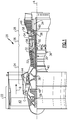
- FIG. 1 schematically illustrates an example gas turbine engine 20 that includes a fan section 22, a compressor section 24, a combustor section 26 and a turbine section 28.
- Alternative engines might include an augmenter section (not shown) among other systems or features.
- the fan section 22 drives air along a bypass flow path B while the compressor section 24 draws air in along a core flow path C where air is compressed and communicated to a combustor section 26.
- air is mixed with fuel and ignited to generate a high pressure exhaust gas stream that expands through the turbine section 28 where energy is extracted and utilized to drive the fan section 22 and the compressor section 24.
- turbofan gas turbine engine depicts a turbofan gas turbine engine
- the concepts described herein are not limited to use with turbofans as the teachings may be applied to other types of turbine engines; for example a turbine engine including a three-spool architecture in which three spools concentrically rotate about a common axis such that a low spool enables a low pressure turbine to drive a fan via a gearbox, an intermediate spool enables an intermediate pressure turbine to drive a first compressor of the compressor section, and a high spool enables a high pressure turbine to drive a high pressure compressor of the compressor section.
- the example engine 20 generally includes a low speed spool 30 and a high speed spool 32 mounted for rotation about an engine central longitudinal axis A relative to an engine static structure 36 via several bearing systems 38. It should be understood that various bearing systems 38 at various locations may alternatively or additionally be provided.
- the low speed spool 30 generally includes an inner shaft 40 that connects a fan 42 and a low pressure (or first) compressor section 44 to a low pressure (or first) turbine section 46.
- the inner shaft 40 drives the fan 42 through a speed change device, such as a geared architecture 48, to drive the fan 42 at a lower speed than the low speed spool 30.
- the high-speed spool 32 includes an outer shaft 50 that interconnects a high pressure (or second) compressor section 52 and a high pressure (or second) turbine section 54.
- the inner shaft 40 and the outer shaft 50 are concentric and rotate via the bearing systems 38 about the engine central longitudinal axis A.
- a combustor 56 is arranged between the high pressure compressor 52 and the high pressure turbine 54.
- the high pressure turbine 54 includes at least two stages to provide a double stage high pressure turbine 54.
- the high pressure turbine 54 includes only a single stage.
- a "high pressure" compressor or turbine experiences a higher pressure than a corresponding "low pressure” compressor or turbine.
- the example low pressure turbine 46 has a pressure ratio that is greater than about 5.
- the pressure ratio of the example low pressure turbine 46 is measured prior to an inlet of the low pressure turbine 46 as related to the pressure measured at the outlet of the low pressure turbine 46 prior to an exhaust nozzle.
- a mid-turbine frame 58 of the engine static structure 36 is arranged generally between the high pressure turbine 54 and the low pressure turbine 46.
- the mid-turbine frame 58 further supports bearing systems 38 in the turbine section 28 as well as setting airflow entering the low pressure turbine 46.
- the core airflow C is compressed by the low pressure compressor 44 then by the high pressure compressor 52 mixed with fuel and ignited in the combustor 56 to produce high speed exhaust gases that are then expanded through the high pressure turbine 54 and low pressure turbine 46.
- the mid-turbine frame 58 includes vanes 60, which are in the core airflow path and function as an inlet guide vane for the low pressure turbine 46. Utilizing the vane 60 of the mid-turbine frame 58 as the inlet guide vane for low pressure turbine 46 decreases the length of the low pressure turbine 46 without increasing the axial length of the mid-turbine frame 58. Reducing or eliminating the number of vanes in the low pressure turbine 46 shortens the axial length of the turbine section 28. Thus, the compactness of the gas turbine engine 20 is increased and a higher power density may be achieved.
- the disclosed gas turbine engine 20 in one example is a high-bypass geared aircraft engine.
- the gas turbine engine 20 includes a bypass ratio greater than about six, with an example embodiment being greater than about ten.
- the example geared architecture 48 is an epicyclical gear train, such as a planetary gear system, star gear system or other known gear system, with a gear reduction ratio of greater than about 2.3.
- the gas turbine engine 20 includes a bypass ratio greater than about ten and the fan diameter is significantly larger than an outer diameter of the low pressure compressor 44. It should be understood, however, that the above parameters are only exemplary of one embodiment of a gas turbine engine including a geared architecture and that the present disclosure is applicable to other gas turbine engines.
- the fan section 22 of the engine 20 is designed for a particular flight condition -- typically cruise at about 0.8 Mach and about 35,000 feet (10,668 m).
- the flight condition of 0.8 Mach and 35,000 ft. (10,668 m) with the engine at its best cruise fuel consumption relative to the thrust it produces - also known as "bucket cruise Thrust Specific Fuel Consumption ('TSFC')" - is the industry standard parameter of pound-mass (lbm) of fuel per hour being burned divided by pound-force (lbf) of thrust the engine produces at that minimum bucket cruise point.
- Low fan pressure ratio is the pressure ratio across the fan blade alone, without a Fan Exit Guide Vane (“FEGV”) system.
- the low fan pressure ratio as disclosed herein according to one non-limiting embodiment is less than about 1.50. In another non-limiting embodiment the low fan pressure ratio is less than about 1.45.
- Low corrected fan tip speed is the actual fan tip speed in ft/sec divided by an industry standard temperature correction of [(Tram °R) / 518.7) 0.5 ].
- the "Low corrected fan tip speed”, as disclosed herein according to one non-limiting embodiment, is less than about 1150 ft/second (350.52 m/s).
- the example gas turbine engine includes the fan 42 that comprises in one non-limiting embodiment less than about 26 fan blades. In another non-limiting embodiment, the fan section 22 includes less than about 18 fan blades. Moreover, in one disclosed embodiment the low pressure turbine 46 includes no more than about 6 turbine stages schematically indicated at 34. In another non-limiting example embodiment the low pressure turbine 46 includes about 3 or more turbine stages. A ratio between the number of fan blades 42 and the number of low pressure turbine stages is between 2.5 and 8.5. The example low pressure turbine 46 provides the driving power to rotate the fan section 22 and therefore the relationship between the number of turbine stages 34 in the low pressure turbine 46 and the number of blades 42 in the fan section 22 disclose an example gas turbine engine 20 with increased power transfer efficiency.
- Increased power transfer efficiency is provided due in part to the increased use of improved turbine blade materials and manufacturing methods such as directionally solidified castings, and single crystal materials that enable increased turbine speed and a reduced number of stages.
- the example low pressure turbine 46 includes improved turbine disks configurations that further enable desired durability at the higher turbine speeds.
- an example disclosed speed change device is an epicyclical gearbox of a planet type, where the input is to the center "sun" gear 62.
- Planet gears 64 (only one shown) around the sun gear 62 rotate and are spaced apart by a carrier 68 that rotates in a direction common to the sun gear 62.
- a ring gear 66 which is non-rotatably fixed to the engine static casing 36 (shown in Figure 1 ), contains the entire gear assembly.
- the fan 42 is attached to and driven by the carrier 68 such that the direction of rotation of the fan 42 is the same as the direction of rotation of the carrier 68 that, in turn, is the same as the direction of rotation of the input sun gear 62.
- fan drive turbine is utilized to indicate the turbine that provides the driving power for rotating the blades 42 of the fan section 22.
- second turbine is utilized to indicate the turbine before the fan drive turbine that is not utilized to drive the fan 42.
- the fan drive turbine is the low pressure turbine 46
- the second turbine is the high pressure turbine 54.
- a three spool engine configuration may include an intermediate turbine (not shown) utilized to drive the fan section 22 and is within the contemplation of this disclosure.
- the fan drive turbine is the low pressure turbine 46 and therefore the fan section 22 and low pressure turbine 46 rotate in a common direction as indicated by the common "+" sign indicating rotation of both the fan 42 and the low pressure turbine 46.
- the high pressure turbine 54 or second turbine rotates in a direction common with the fan drive turbine 46.
- the high pressure turbine 54 or second turbine rotates in a direction opposite the fan drive turbine (low pressure turbine 46) and the fan 42.
- another example disclosed speed change device is an epicyclical gearbox referred to as a star type gearbox, where the input is to the center "sun" gear 62.
- Star gears 65 (only one shown) around the sun gear 62 rotate in a fixed position around the sun gear and are spaced apart by a carrier 68 that is fixed to a static casing 36 (best shown in Figure 1 ).
- a ring gear 66 that is free to rotate contains the entire gear assembly.
- the fan 42 is attached to and driven by the ring gear 66 such that the direction of rotation of the fan 42 is opposite the direction of rotation of the input sun gear 62. Accordingly, the low pressure compressor 44 and the low pressure turbine 46 rotate in a direction opposite rotation of the fan 42.
- the fan drive turbine is the low pressure turbine 46 and therefore the fan 42 rotates in a direction opposite that of the low pressure turbine 46 and the low pressure compressor 44.
- the high spool 32 including the high pressure turbine 54 and the high pressure compressor 52 rotate in a direction counter to the fan 42 and common with the low spool 30 including the low pressure compressor 44 and the fan drive turbine 46.
- the high pressure or second turbine 54 rotates in a direction common with the fan 42 and counter to the low spool 30 including the low pressure compressor 44 and the fan drive turbine 46.
- the bearing assemblies near the forward end of the shafts in the engine at locations 70 and 72 which bearings support rotation of the inner shaft 40 and the outer shaft 50, counter net thrust forces in a direction parallel to the axis A that are generated by the rearward load of low pressure turbine 46 and the high pressure turbine 54, minus the high pressure compressor 52 and the low pressure compressor 44, which also contribute to the thrust forces acting on the corresponding low spool 30 and the high spool 32.
- a first forward bearing assembly 70 is supported on a portion of the static structure schematically shown at 36 and supports a forward end of the inner shaft 40.
- the example first forward bearing assembly 70 is a thrust bearing and controls movement of the inner shaft 40 and thereby the low spool 30 in an axial direction.
- a second forward bearing assembly 72 is supported by the static structure 36 to support rotation of the high spool 32 and substantially prevent movement along in an axial direction of the outer shaft 50.
- the first forward bearing assembly 70 is mounted to support the inner shaft 40 at a point forward of a connection 88 of a low pressure compressor rotor 90.
- the second forward bearing assembly 72 is mounted forward of a connection referred to as a hub 92 between a high pressure compressor rotor 94 and the outer shaft 50.
- a first aft bearing assembly 74 supports the aft portion of the inner shaft 40.
- the first aft bearing assembly 74 is a roller bearing and supports rotation, but does not provide resistance to movement of the shaft 40 in the axial direction. Instead, the aft bearing 74 allows the shaft 40 to expand thermally between its location and the bearing 72.
- the example first aft bearing assembly 74 is disposed aft of a connection hub 80 between a low pressure turbine rotor 78 and the inner shaft 40.
- a second aft bearing assembly 76 supports the aft portion of the outer shaft 50.
- the example second aft bearing assembly 76 is a roller bearing and is supported by a corresponding static structure 36 through the mid turbine frame 58 which transfers the radial load of the shaft across the turbine flow path to ground 36.
- the second aft bearing assembly 76 supports the outer shaft 50 and thereby the high spool 32 at a point aft of a connection hub 84 between a high pressure turbine rotor 82 and the outer shaft 50.
- first and second forward bearing assemblies 70, 72 and the first and second aft bearing assemblies 74, 76 are supported to the outside of either the corresponding compressor or turbine connection hubs 80, 88 to provide a straddle support configuration of the corresponding inner shaft 40 and outer shaft 50.
- the straddle support of the inner shaft 40 and the outer shaft 50 provide a support and stiffness desired for operation of the gas turbine engine 20.
- another shaft support configuration includes the first and second forward bearing assemblies 70, 72 disposed to support the forward portion of the corresponding inner shaft 40 and outer shaft 50.
- the first aft bearing 74 is disposed aft of the connection 80 between the rotor 78 and the inner shaft 40.
- the first aft bearing 74 is a roller bearing and supports the inner shaft 40 in a straddle configuration.
- the straddle configuration can require additional length of the inner shaft 40 and therefore an alternate configuration referred to as an overhung configuration can be utilized.
- the outer shaft 50 is supported by the second aft bearing assembly 76 that is disposed forward of the connection 84 between the high pressure turbine rotor 82 and the outer shaft 50.
- connection hub 84 of the high pressure turbine rotor 82 to the outer shaft 50 is overhung aft of the bearing assembly 76.
- This positioning of the second aft bearing 76 in an overhung orientation potentially provides for a reduced length of the outer shaft 50.
- the positioning of the aft bearing 76 may also eliminate the need for other support structures such as the mid turbine frame 58 as both the high pressure turbine 54 is supported at the bearing assembly 76 and the low pressure turbine 46 is supported by the bearing assembly 74.
- the mid turbine frame strut 58 can provide an optional roller bearing 74A which can be added to reduce vibratory modes of the inner shaft 40.
- another shaft support configuration includes the first and second forward bearing assemblies 70, 72 disposed to support corresponding forward portions of each of the inner shaft 40 and the outer shaft 50.
- the first aft bearing 74 provides support of the outer shaft 40 at a location aft of the connection 80 in a straddle mount configuration.
- the aft portion of the outer shaft 50 is supported by a roller bearing assembly 86 supported within a space 96 defined between an outer surface of the inner shaft 40 and an inner surface of the outer shaft 50.
- the roller bearing assembly 86 supports the aft portion of the outer shaft 50 on the inner shaft 40.
- the use of the roller bearing assembly 86 to support the outer shaft 50 eliminates the requirements for support structures that lead back to the static structure 36 through the mid turbine frame 58.
- the bearing assembly 86 can provide both a reduced shaft length, and support of the outer shaft 50 at a position substantially in axial alignment with the connection hub 84 for the high pressure turbine rotor 82 and the outer shaft 50.
- the bearing assembly 86 is positioned aft of the hub 82 and is supported through the rearmost section of shaft 50.
- an example shaft support configuration includes the first and second forward bearing assemblies 70, 72 disposed to support corresponding forward portions of each of the inner shaft 40 and the outer shaft 50.
- the first aft bearing assembly 74 is supported at a point along the inner shaft 40 forward of the connection 80 between the low pressure turbine rotor 78 and the inner shaft 40.
- Positioning of the first aft bearing 74 forward of the connection 80 can be utilized to reduce the overall length of the engine 20. Moreover, positioning of the first aft bearing assembly 74 forward of the connection 80 provides for support through the mid turbine frame 58 to the static structure 36. Furthermore, in this example the second aft bearing assembly 76 is deployed in a straddle mount configuration aft of the connection 84 between the outer shaft 50 and the rotor 82. Accordingly, in this example, both the first and second aft bearing assemblies 74, 76 share a common support structure to the static outer structure 36. As appreciated, such a common support feature provides for a less complex engine construction along with reducing the overall length of the engine. Moreover, the reduction or required support structures will reduce overall weight to provide a further improvement in aircraft fuel burn efficiency.
- a portion of the example turbine section 28 is shown and includes the low pressure turbine 46 and the high pressure turbine 54 with the mid turbine frame 58 disposed between an outlet of the high pressure turbine and the low pressure turbine.
- the mid turbine frame 58 and vane 60 are positioned to be upstream of the first stage 98 of the low pressure turbine 46. While a single vane 60 is illustrated, it should be understood these would be plural vanes 60 spaced circumferentially.
- the vane 60 redirects the flow downstream of the high pressure turbine 54 as it approaches the first stage 98 of the low pressure turbine 46.
- vane 60 may be an actual airfoil with camber and turning, that aligns the airflow as desired into the low pressure turbine 46.
- the overall length and volume of the combined turbine sections 46, 54 is reduced because the vane 60 serves several functions including streamlining the mid turbine frame 58, protecting any static structure and any oil tubes servicing a bearing assembly from exposure to heat, and turning the flow entering the low pressure turbine 46 such that it enters the rotating airfoil 100 at a desired flow angle. Further, by incorporating these features together, the overall assembly and arrangement of the turbine section 28 is reduced in volume.
- the materials for forming the low pressure turbine 46 can be improved to provide for a reduced volume.
- Such materials may include, for example, materials with increased thermal and mechanical capabilities to accommodate potentially increased stresses induced by operating the low pressure turbine 46 at the increased speed.
- the elevated speeds and increased operating temperatures at the entrance to the low pressure turbine 46 enables the low pressure turbine 46 to transfer a greater amount of energy, more efficiently to drive both a larger diameter fan 42 through the geared architecture 48 and an increase in compressor work performed by the low pressure compressor 44.
- a first rotating blade 100 of the low pressure turbine 46 can be a directionally solidified casting blade, a single crystal casting blade or a hollow, internally cooled blade.
- the improved material and thermal properties of the example turbine blade material provide for operation at increased temperatures and speeds, that in turn provide increased efficiencies at each stage that thereby provide for use of a reduced number of low pressure turbine stages.
- the reduced number of low pressure turbine stages in turn provide for an overall turbine volume that is reduced, and that accommodates desired increases in low pressure turbine speed.
- the reduced stages and reduced volume provide improve engine efficiency and aircraft fuel burn because overall weight is less.
- there are fewer blade rows there are: fewer leakage paths at the tips of the blades; fewer leakage paths at the inner air seals of vanes; and reduced losses through the rotor stages.
- the example disclosed compact turbine section includes a power density, which may be defined as thrust in pounds force (lbf) produced divided by the volume of the entire turbine section 28.
- the volume of the turbine section 28 may be defined by an inlet 102 of a first turbine vane 104 in the high pressure turbine 54 to the exit 106 of the last rotating airfoil 108 in the low pressure turbine 46, and may be expressed in cubic inches.
- the static thrust at the engine's flat rated Sea Level Takeoff condition divided by a turbine section volume is defined as power density and a greater power density may be desirable for reduced engine weight.
- the sea level take-off flat-rated static thrust may be defined in pounds-force (lbf), while the volume may be the volume from the annular inlet 102 of the first turbine vane 104 in the high pressure turbine 54 to the annular exit 106 of the downstream end of the last airfoil 108 in the low pressure turbine 46.
- the maximum thrust may be Sea Level Takeoff Thrust "SLTO thrust" which is commonly defined as the flat-rated static thrust produced by the turbofan at sea-level.
- the volume V of the turbine section may be best understood from Figure 10 .
- the mid turbine frame 58 is disposed between the high pressure turbine 54, and the low pressure turbine 46.
- the volume V is illustrated by a dashed line, and extends from an inner periphery I to an outer periphery O.
- the inner periphery is defined by the flow path of rotors, but also by an inner platform flow paths of vanes.
- the outer periphery is defined by the stator vanes and outer air seal structures along the flowpath.
- the volume extends from a most upstream end of the vane 104, typically its leading edge, and to the most downstream edge of the last rotating airfoil 108 in the low pressure turbine section 46. Typically this will be the trailing edge of the airfoil 108.
- the power density is greater than 1.5 lbf/in 3 (407.17 kN/m 3 ). More narrowly, the power density would be greater than or equal to about 2.0 lbf/in 3 (542.9 kN/m 3 ). Even more narrowly, the power density would be greater than or equal to about 3.0 lbf/in 3 (814.3 kN/m 3 ). More narrowly, the power density is greater than or equal to about 4.0 lbf/in 3 (1086 kN/m 3 ). Also, the power density is less than or equal to about 5.5 lbf/in 3 (1493 kN/m 3 ).
- An exit area 112 is defined at the exit location for the high pressure turbine 54 and an exit area 110 is defined at the outlet 106 of the low pressure turbine 46.
- the gear reduction 48 (shown in Figure 1 ) provides for a range of different rotational speeds of the fan drive turbine, which in this example embodiment is the low pressure turbine 46, and the fan 42 ( Figure 1 ). Accordingly, the low pressure turbine 46, and thereby the low spool 30 including the low pressure compressor 44 may rotate at a very high speed. Low pressure turbine 46 and high pressure turbine 54 operation may be evaluated looking at a performance quantity which is the exit area for the respective turbine section multiplied by its respective speed squared.
- PQ This performance quantity
- PQ ltp A lpt ⁇ V lpt 2
- PQ hpt A hpt ⁇ V hpt 2
- a lpt is the area 110 of the low pressure turbine 46 at the exit 106
- V lpt is the speed of the low pressure turbine section
- a hpt is the area of the high pressure turbine 54 at the exit 114
- V hpt is the speed of the high pressure turbine 54.
- a lpt ⁇ V lpt 2 / A hpt ⁇ V hpt 2 PQ ltp / PQ hpt
- the areas of the low and high pressure turbines 46, 54 are 557.9 in 2 (3,599.3 cm 2 ) and 90.67 in 2 (585.0 cm 2 ), respectively. Further, the speeds of the low and high pressure turbine 46, 54 are 10179 rpm and 24346 rpm, respectively.
- the ratio is greater than about 0.5 and in another embodiment the ratio is greater than about 0.8.
- PQ ltp/ PQ hpt ratios in the 0.5 to 1.5 range a very efficient overall gas turbine engine is achieved. More narrowly, PQ ltp/ PQ hpt ratios of above or equal to about 0.8 provides increased overall gas turbine efficiency. Even more narrowly, PQ ltp/ PQ hpt ratios above or equal to 1.0 are even more efficient thermodynamically and from an enable a reduction in weight that improves aircraft fuel burn efficiency. As a result of these PQ ltp/ PQ hpt ratios, in particular, the turbine section 28 can be made much smaller than in the prior art, both in diameter and axial length. In addition, the efficiency of the overall engine is greatly increased.
- portions of the low pressure compressor 44 and the low pressure turbine 46 of the low spool 30 are schematically shown and include rotors 116 of the low pressure turbine 46 and rotors 132 of the low pressure compressor 44.
- Each of the rotors 116 includes a bore radius 122, a live disk radius 124 and a bore width 126 in a direction parallel to the axis A.
- the rotor 116 supports turbine blades 118 that rotate relative to the turbine vanes 120.
- the low pressure compressor 44 includes rotors 132 including a bore radius 134, a live disk radius 136 and a bore width 138.
- the rotor 132 supports compressor blades 128 that rotate relative to vanes 130.
- the bore radius 122 is that radius between an inner most surface of the bore and the axis.
- the live disk radius 124 is the radial distance from the axis of rotation A and a portion of the rotor supporting airfoil blades.
- the bore width 126 of the rotor in this example is the greatest width of the rotor and is disposed at a radial distance spaced apart form the axis A determined to provide desired physical performance properties.
- the rotors for each of the low compressor 44 and the low pressure turbine 46 rotate at an increased speed compared to prior art low spool configurations.
- the geometric shape including the bore radius, live disk radius and the bore width are determined to provide the desired rotor performance in view of the mechanical and thermal stresses selected to be imposed during operation.
- a turbine rotor 116 is shown to further illustrate the relationship between the bore radius 126 and the live disk radius 124.
- the relationships disclosed are provided within a known range of materials commonly utilized for construction of each of the rotors.
Landscapes
- Engineering & Computer Science (AREA)
- Chemical & Material Sciences (AREA)
- Combustion & Propulsion (AREA)
- Mechanical Engineering (AREA)
- General Engineering & Computer Science (AREA)
- Structures Of Non-Positive Displacement Pumps (AREA)
Claims (15)
- Moteur à turbine à gaz (20) comprenant :une section de compresseur (24) ;une chambre de combustion (56) en communication fluidique avec la section de compresseur (24) ;une section de turbine (28) en communication fluidique avec la chambre de combustion (56), la section de turbine (28) comprenant une turbine d'entraînement de ventilateur (46) et une seconde turbine (54), la turbine d'entraînement de ventilateur (46) comprenant une pluralité d'étages de turbine (34) ;un ventilateur (22) comprenant une pluralité de pales (45) pouvant tourner autour d'un axe (A) ; etun système de changement de vitesse (48) entraîné par la turbine d'entraînement de ventilateur (46) pour faire tourner le ventilateur (22) autour de l'axe (A), dans lequel la turbine d'entraînement de ventilateur (46) comprend un premier rotor arrière (78) fixé à un premier arbre (40) et la seconde turbine (54) comprend un second rotor arrière (82) fixé à un second arbre (50), caractérisé en ce que :un rapport entre le nombre de pales de ventilateur (45) et le nombre d'étages de turbine d'entraînement de ventilateur (34) est compris entre 2,5 et 8,5 ; etun premier ensemble de palier (74) est disposé axialement vers l'avant d'une première connexion (80) entre le premier rotor arrière (78) et le premier arbre (40), et un second ensemble de palier (76) est disposé axialement à l'arrière d'une seconde connexion (84) entre le second rotor arrière (82) et le second arbre (50) ; etle moteur (20) comprend une densité de puissance supérieure à 1,5 lbf/in3 (407,17 kN/m3) et inférieure ou égale à environ 5,5 lbf/in3 (1 493,96 kN/m3), dans lequel la densité de puissance est la poussée statique détarée de décollage au niveau de la mer divisée par le volume de la section de turbine (28).
- Moteur (20) selon la revendication 1, dans lequel le premier ensemble de palier (74) et le second ensemble de palier (76) comprennent des roulements à rouleaux.
- Moteur (20) selon la revendication 1 ou 2, dans lequel la section de compresseur (24) comprend un premier compresseur (44) entraîné par la turbine d'entraînement de ventilateur (46) à travers le premier arbre (40) et une seconde section de compresseur (52) entraînée par la seconde turbine (54) à travers le second arbre (50), dans lequel le premier ensemble de palier (74) supporte une partie arrière du premier arbre (40) et le second ensemble de palier (76) supporte une partie arrière du second arbre (50).
- Moteur (20) selon la revendication 3, dans lequel une partie avant de chacun des premier et second arbres (40, 50) est supportée par un ensemble de palier de poussée (70, 72).
- Moteur (20) selon une quelconque revendication précédente, dans lequel le système de changement de vitesse (48) comprend une boîte de vitesses, le ventilateur (22) et la turbine d'entraînement de ventilateur (46) tournent tous deux dans une première direction autour de l'axe (A), et la seconde turbine (54) tourne dans une seconde direction opposée à la première direction.
- Moteur (20) selon l'une quelconque des revendications 1 à 4, dans lequel le système de changement de vitesse (48) comprend une boîte de vitesses, et le ventilateur (22), la turbine d'entraînement de ventilateur (46) et la seconde turbine (54) tournent tous dans une première direction autour de l'axe (A).
- Moteur (20) selon l'une quelconque des revendications 1 à 4, dans lequel le système de changement de vitesse (48) comprend une boîte de vitesses, le ventilateur (22) et la seconde section de turbine (54) tournent tous deux dans une première direction autour de l'axe (A), et la turbine d'entraînement de ventilateur (46) tourne dans une seconde direction opposée à la première direction.
- Moteur (20) selon l'une quelconque des revendications 1 à 4, dans lequel le système de changement de vitesse (48) comprend une boîte de vitesses, le ventilateur (22) peut tourner dans une première direction, et la turbine d'entraînement de ventilateur (46) et la seconde section de turbine (54) tournent dans une seconde direction opposée à la première direction autour de l'axe (A).
- Moteur (20) selon une quelconque revendication précédente, dans lequel le système de changement de vitesse (48) comprend une réduction d'engrenage ayant un rapport d'engrenage supérieur à 2, 3.
- Moteur (20) selon une quelconque revendication précédente, dans lequel le ventilateur (22) délivre une partie de l'air (B) dans un conduit de dérivation, et un rapport de dérivation, étant défini comme la partie de l'air (B) délivrée dans le conduit de dérivation divisée par la quantité d'air délivrée dans la section de compresseur (24), est supérieur à 6,0 ou supérieur à 10,0.
- Moteur (20) selon une quelconque revendication précédente, dans lequel un rapport de pression de ventilateur à travers le ventilateur (22) est inférieur à 1,5.
- Moteur (20) selon une quelconque revendication précédente, dans lequel un rapport de pression à travers la turbine d'entraînement de ventilateur (46) est supérieur à 5:1.
- Moteur (20) selon une quelconque revendication précédente, dans lequel le ventilateur (22) a 26 pales ou moins (45).
- Moteur (20) selon une quelconque revendication précédente, dans lequel ladite turbine d'entraînement de ventilateur (46) a entre 3 et 6 étages.
- Moteur (20) selon une quelconque revendication précédente, dans lequel la seconde turbine (54) comprend au moins deux étages et fonctionne à une première pression et la turbine d'entraînement de ventilateur (46) comprend plus de deux étages et fonctionne à une seconde pression inférieure à la première pression.
Priority Applications (1)
| Application Number | Priority Date | Filing Date | Title |
|---|---|---|---|
| EP17204160.0A EP3312080A1 (fr) | 2012-01-31 | 2013-01-30 | Architecture de moteur de turbine à gaz et turboréacteur à engrenages |
Applications Claiming Priority (4)
| Application Number | Priority Date | Filing Date | Title |
|---|---|---|---|
| US13/363,154 US20130192196A1 (en) | 2012-01-31 | 2012-01-31 | Gas turbine engine with high speed low pressure turbine section |
| US201261653814P | 2012-05-31 | 2012-05-31 | |
| US13/645,807 US8887487B2 (en) | 2012-01-31 | 2012-10-05 | Geared turbofan gas turbine engine architecture |
| PCT/US2013/023724 WO2013116259A1 (fr) | 2012-01-31 | 2013-01-30 | Architecture d'un moteur à turbine à gaz à turboréacteur à double flux et à engrenage |
Related Child Applications (1)
| Application Number | Title | Priority Date | Filing Date |
|---|---|---|---|
| EP17204160.0A Division EP3312080A1 (fr) | 2012-01-31 | 2013-01-30 | Architecture de moteur de turbine à gaz et turboréacteur à engrenages |
Publications (3)
| Publication Number | Publication Date |
|---|---|
| EP2809932A1 EP2809932A1 (fr) | 2014-12-10 |
| EP2809932A4 EP2809932A4 (fr) | 2015-11-04 |
| EP2809932B1 true EP2809932B1 (fr) | 2017-12-20 |
Family
ID=48905765
Family Applications (2)
| Application Number | Title | Priority Date | Filing Date |
|---|---|---|---|
| EP17204160.0A Pending EP3312080A1 (fr) | 2012-01-31 | 2013-01-30 | Architecture de moteur de turbine à gaz et turboréacteur à engrenages |
| EP13743283.7A Revoked EP2809932B1 (fr) | 2012-01-31 | 2013-01-30 | Architecture d'un moteur à turbine à gaz à turboréacteur à double flux et à engrenage |
Family Applications Before (1)
| Application Number | Title | Priority Date | Filing Date |
|---|---|---|---|
| EP17204160.0A Pending EP3312080A1 (fr) | 2012-01-31 | 2013-01-30 | Architecture de moteur de turbine à gaz et turboréacteur à engrenages |
Country Status (7)
| Country | Link |
|---|---|
| US (1) | US8887487B2 (fr) |
| EP (2) | EP3312080A1 (fr) |
| BR (1) | BR112014016303B1 (fr) |
| CA (1) | CA2857359C (fr) |
| RU (1) | RU2630630C2 (fr) |
| SG (1) | SG11201403012PA (fr) |
| WO (1) | WO2013116259A1 (fr) |
Cited By (1)
| Publication number | Priority date | Publication date | Assignee | Title |
|---|---|---|---|---|
| EP3591190B1 (fr) * | 2012-04-02 | 2023-09-06 | Raytheon Technologies Corporation | Turboréacteur double flux à engrenages à trois turbines co-rotatives |
Families Citing this family (34)
| Publication number | Priority date | Publication date | Assignee | Title |
|---|---|---|---|---|
| EP3916205A3 (fr) | 2012-02-29 | 2022-03-16 | Raytheon Technologies Corporation | Moteur de turboréacteur à réducteur équipé d'arbres contrarotatifs |
| US10309232B2 (en) * | 2012-02-29 | 2019-06-04 | United Technologies Corporation | Gas turbine engine with stage dependent material selection for blades and disk |
| FR3020410B1 (fr) * | 2014-04-29 | 2021-09-17 | Snecma | Turbomachine d'aeronef a prelevement de puissance mecanique ameliore |
| US9869190B2 (en) | 2014-05-30 | 2018-01-16 | General Electric Company | Variable-pitch rotor with remote counterweights |
| US10072510B2 (en) | 2014-11-21 | 2018-09-11 | General Electric Company | Variable pitch fan for gas turbine engine and method of assembling the same |
| US9878798B2 (en) | 2014-12-31 | 2018-01-30 | Rolls-Royce North American Technologies Inc. | Aircraft with counter-rotating turbofan engines |
| US11225913B2 (en) | 2015-02-19 | 2022-01-18 | Raytheon Technologies Corporation | Method of providing turbine engines with different thrust ratings |
| US20160333786A1 (en) * | 2015-05-13 | 2016-11-17 | General Electric Company | System for supporting rotor shafts of an indirect drive turbofan engine |
| US10669946B2 (en) | 2015-06-05 | 2020-06-02 | Raytheon Technologies Corporation | Geared architecture for a gas turbine engine |
| US10100653B2 (en) | 2015-10-08 | 2018-10-16 | General Electric Company | Variable pitch fan blade retention system |
| US10590854B2 (en) * | 2016-01-26 | 2020-03-17 | United Technologies Corporation | Geared gas turbine engine |
| US10378770B2 (en) | 2017-01-27 | 2019-08-13 | General Electric Company | Unitary flow path structure |
| US11111858B2 (en) | 2017-01-27 | 2021-09-07 | General Electric Company | Cool core gas turbine engine |
| US10393381B2 (en) | 2017-01-27 | 2019-08-27 | General Electric Company | Unitary flow path structure |
| US10371383B2 (en) | 2017-01-27 | 2019-08-06 | General Electric Company | Unitary flow path structure |
| US10253643B2 (en) | 2017-02-07 | 2019-04-09 | General Electric Company | Airfoil fluid curtain to mitigate or prevent flow path leakage |
| US10370990B2 (en) | 2017-02-23 | 2019-08-06 | General Electric Company | Flow path assembly with pin supported nozzle airfoils |
| US10378373B2 (en) | 2017-02-23 | 2019-08-13 | General Electric Company | Flow path assembly with airfoils inserted through flow path boundary |
| US10247019B2 (en) | 2017-02-23 | 2019-04-02 | General Electric Company | Methods and features for positioning a flow path inner boundary within a flow path assembly |
| US10385776B2 (en) | 2017-02-23 | 2019-08-20 | General Electric Company | Methods for assembling a unitary flow path structure |
| US10385709B2 (en) | 2017-02-23 | 2019-08-20 | General Electric Company | Methods and features for positioning a flow path assembly within a gas turbine engine |
| US10253641B2 (en) | 2017-02-23 | 2019-04-09 | General Electric Company | Methods and assemblies for attaching airfoils within a flow path |
| US10385731B2 (en) | 2017-06-12 | 2019-08-20 | General Electric Company | CTE matching hanger support for CMC structures |
| US11402097B2 (en) | 2018-01-03 | 2022-08-02 | General Electric Company | Combustor assembly for a turbine engine |
| US11204037B2 (en) | 2018-12-21 | 2021-12-21 | Rolls-Royce Plc | Turbine engine |
| GB201820925D0 (en) | 2018-12-21 | 2019-02-06 | Rolls Royce Plc | Turbine engine |
| GB201820924D0 (en) | 2018-12-21 | 2019-02-06 | Rolls Royce Plc | Turbine engine |
| US11268394B2 (en) | 2020-03-13 | 2022-03-08 | General Electric Company | Nozzle assembly with alternating inserted vanes for a turbine engine |
| US11242770B2 (en) | 2020-04-02 | 2022-02-08 | General Electric Company | Turbine center frame and method |
| US11549373B2 (en) | 2020-12-16 | 2023-01-10 | Raytheon Technologies Corporation | Reduced deflection turbine rotor |
| US11428160B2 (en) | 2020-12-31 | 2022-08-30 | General Electric Company | Gas turbine engine with interdigitated turbine and gear assembly |
| US11674435B2 (en) | 2021-06-29 | 2023-06-13 | General Electric Company | Levered counterweight feathering system |
| US11795964B2 (en) | 2021-07-16 | 2023-10-24 | General Electric Company | Levered counterweight feathering system |
| US12601271B2 (en) | 2022-10-21 | 2026-04-14 | General Electric Company | Variable pitch fan of a gas turbine engine |
Citations (5)
| Publication number | Priority date | Publication date | Assignee | Title |
|---|---|---|---|---|
| US3250512A (en) | 1962-11-09 | 1966-05-10 | Rolls Royce | Gas turbine engine |
| US3526092A (en) | 1967-09-15 | 1970-09-01 | Rolls Royce | Gas turbine engine having improved bearing support means for concentric shafts |
| US3527054A (en) | 1969-01-23 | 1970-09-08 | Gen Electric | Pressurization of lubrication sumps in gas turbine engines |
| US4304522A (en) | 1980-01-15 | 1981-12-08 | Pratt & Whitney Aircraft Of Canada Limited | Turbine bearing support |
| FR2912181A1 (fr) | 2007-02-07 | 2008-08-08 | Snecma Sa | Turbine a gaz a turbines hp et bp contra-rotatives |
Family Cites Families (67)
| Publication number | Priority date | Publication date | Assignee | Title |
|---|---|---|---|---|
| US3111005A (en) | 1963-11-19 | Jet propulsion plant | ||
| US2608821A (en) | 1949-10-08 | 1952-09-02 | Gen Electric | Contrarotating turbojet engine having independent bearing supports for each turbocompressor |
| US2748623A (en) | 1952-02-05 | 1956-06-05 | Boeing Co | Orbit gear controlled reversible planetary transmissions |
| US3033002A (en) | 1957-11-08 | 1962-05-08 | Fairfield Shipbuilding And Eng | Marine propulsion steam turbine installations |
| GB1305302A (fr) | 1970-04-28 | 1973-01-31 | ||
| US3673802A (en) | 1970-06-18 | 1972-07-04 | Gen Electric | Fan engine with counter rotating geared core booster |
| GB1350431A (en) | 1971-01-08 | 1974-04-18 | Secr Defence | Gearing |
| GB1309721A (en) * | 1971-01-08 | 1973-03-14 | Secr Defence | Fan |
| US3747343A (en) | 1972-02-10 | 1973-07-24 | United Aircraft Corp | Low noise prop-fan |
| US3861139A (en) * | 1973-02-12 | 1975-01-21 | Gen Electric | Turbofan engine having counterrotating compressor and turbine elements and unique fan disposition |
| FR2506840A1 (fr) | 1981-05-29 | 1982-12-03 | Onera (Off Nat Aerospatiale) | Turboreacteur a roues contra-rotatives |
| US4660376A (en) | 1984-04-27 | 1987-04-28 | General Electric Company | Method for operating a fluid injection gas turbine engine |
| GB8605092D0 (en) * | 1986-02-28 | 1986-04-09 | Lucas Ind Plc | Brake actuators |
| GB8630754D0 (en) | 1986-12-23 | 1987-02-04 | Rolls Royce Plc | Turbofan gas turbine engine |
| GB2207191B (en) * | 1987-07-06 | 1992-03-04 | Gen Electric | Gas turbine engine |
| US5010729A (en) * | 1989-01-03 | 1991-04-30 | General Electric Company | Geared counterrotating turbine/fan propulsion system |
| FR2644844B1 (fr) | 1989-03-23 | 1994-05-06 | Snecma | Suspension du rotor de la turbine basse pression d'une turbomachine a double corps |
| US5307622A (en) | 1993-08-02 | 1994-05-03 | General Electric Company | Counterrotating turbine support assembly |
| US5971706A (en) | 1997-12-03 | 1999-10-26 | General Electric Company | Inter-rotor bearing assembly |
| JP2002512337A (ja) | 1998-04-16 | 2002-04-23 | 3カー−ヴァルナー・トゥルボズュステームズ・ゲーエムベーハー | ターボチャージ付内燃機関 |
| DE19828562B4 (de) | 1998-06-26 | 2005-09-08 | Mtu Aero Engines Gmbh | Triebwerk mit gegenläufig drehenden Rotoren |
| USH2032H1 (en) | 1999-10-01 | 2002-07-02 | The United States Of America As Represented By The Secretary Of The Air Force | Integrated fan-core twin spool counter-rotating turbofan gas turbine engine |
| EP1780387A3 (fr) | 2000-09-05 | 2007-07-18 | Sudarshan Paul Dev | Turbine à gaz à coeur emboîté |
| US6669393B2 (en) | 2001-10-10 | 2003-12-30 | General Electric Co. | Connector assembly for gas turbine engines |
| US6708482B2 (en) * | 2001-11-29 | 2004-03-23 | General Electric Company | Aircraft engine with inter-turbine engine frame |
| US20030097872A1 (en) | 2001-11-29 | 2003-05-29 | Granitz Charles Robert | System for reducing oil consumption in gas turbine engines |
| US6619030B1 (en) | 2002-03-01 | 2003-09-16 | General Electric Company | Aircraft engine with inter-turbine engine frame supported counter rotating low pressure turbine rotors |
| US6732502B2 (en) | 2002-03-01 | 2004-05-11 | General Electric Company | Counter rotating aircraft gas turbine engine with high overall pressure ratio compressor |
| GB0315894D0 (en) | 2003-07-08 | 2003-08-13 | Rolls Royce Plc | Aircraft engine arrangement |
| US7137245B2 (en) | 2004-06-18 | 2006-11-21 | General Electric Company | High area-ratio inter-turbine duct with inlet blowing |
| DE102004042739A1 (de) | 2004-09-03 | 2006-03-09 | Mtu Aero Engines Gmbh | Fan für ein Flugtriebwerk sowie Flugtriebwerk |
| US7409819B2 (en) * | 2004-10-29 | 2008-08-12 | General Electric Company | Gas turbine engine and method of assembling same |
| US7309210B2 (en) * | 2004-12-17 | 2007-12-18 | United Technologies Corporation | Turbine engine rotor stack |
| US7845902B2 (en) | 2005-02-15 | 2010-12-07 | Massachusetts Institute Of Technology | Jet engine inlet-fan system and design method |
| US7374403B2 (en) | 2005-04-07 | 2008-05-20 | General Electric Company | Low solidity turbofan |
| WO2008060257A2 (fr) | 2005-05-25 | 2008-05-22 | Lau Daniel L | Système de repérage de projectile |
| US7594388B2 (en) | 2005-06-06 | 2009-09-29 | General Electric Company | Counterrotating turbofan engine |
| US20070022735A1 (en) | 2005-07-29 | 2007-02-01 | General Electric Company | Pto assembly for a gas turbine engine |
| US7685808B2 (en) * | 2005-10-19 | 2010-03-30 | General Electric Company | Gas turbine engine assembly and methods of assembling same |
| US7513103B2 (en) | 2005-10-19 | 2009-04-07 | General Electric Company | Gas turbine engine assembly and methods of assembling same |
| US7600370B2 (en) | 2006-05-25 | 2009-10-13 | Siemens Energy, Inc. | Fluid flow distributor apparatus for gas turbine engine mid-frame section |
| US7594404B2 (en) * | 2006-07-27 | 2009-09-29 | United Technologies Corporation | Embedded mount for mid-turbine frame |
| US7694505B2 (en) | 2006-07-31 | 2010-04-13 | General Electric Company | Gas turbine engine assembly and method of assembling same |
| US7832193B2 (en) | 2006-10-27 | 2010-11-16 | General Electric Company | Gas turbine engine assembly and methods of assembling same |
| US7926259B2 (en) | 2006-10-31 | 2011-04-19 | General Electric Company | Turbofan engine assembly and method of assembling same |
| US7966806B2 (en) | 2006-10-31 | 2011-06-28 | General Electric Company | Turbofan engine assembly and method of assembling same |
| US7882693B2 (en) | 2006-11-29 | 2011-02-08 | General Electric Company | Turbofan engine assembly and method of assembling same |
| US7716914B2 (en) | 2006-12-21 | 2010-05-18 | General Electric Company | Turbofan engine assembly and method of assembling same |
| US20080148881A1 (en) | 2006-12-21 | 2008-06-26 | Thomas Ory Moniz | Power take-off system and gas turbine engine assembly including same |
| US7721549B2 (en) | 2007-02-08 | 2010-05-25 | United Technologies Corporation | Fan variable area nozzle for a gas turbine engine fan nacelle with cam drive ring actuation system |
| US8015828B2 (en) | 2007-04-03 | 2011-09-13 | General Electric Company | Power take-off system and gas turbine engine assembly including same |
| US8256707B2 (en) | 2007-08-01 | 2012-09-04 | United Technologies Corporation | Engine mounting configuration for a turbofan gas turbine engine |
| US9957918B2 (en) | 2007-08-28 | 2018-05-01 | United Technologies Corporation | Gas turbine engine front architecture |
| US8205432B2 (en) | 2007-10-03 | 2012-06-26 | United Technologies Corporation | Epicyclic gear train for turbo fan engine |
| GB0720628D0 (en) | 2007-10-20 | 2007-11-28 | Rolls Royce Plc | Bearing arrangement |
| US8590286B2 (en) | 2007-12-05 | 2013-11-26 | United Technologies Corp. | Gas turbine engine systems involving tip fans |
| RU73697U1 (ru) * | 2007-12-24 | 2008-05-27 | Валерий Иванович Сафонов | Турбовинтовентиляторный двигатель |
| RU2371598C2 (ru) * | 2008-01-09 | 2009-10-27 | Валерий Иванович Сафонов | Турбовинтовентиляторный двигатель |
| US7762086B2 (en) | 2008-03-12 | 2010-07-27 | United Technologies Corporation | Nozzle extension assembly for ground and flight testing |
| DE102008023990A1 (de) * | 2008-05-16 | 2009-11-19 | Rolls-Royce Deutschland Ltd & Co Kg | Zwei-Wellen-Triebwerk für eine Fluggasturbine |
| US20100005810A1 (en) | 2008-07-11 | 2010-01-14 | Rob Jarrell | Power transmission among shafts in a turbine engine |
| US8166748B2 (en) | 2008-11-21 | 2012-05-01 | General Electric Company | Gas turbine engine booster having rotatable radially inwardly extending blades and non-rotatable vanes |
| US8061969B2 (en) | 2008-11-28 | 2011-11-22 | Pratt & Whitney Canada Corp. | Mid turbine frame system for gas turbine engine |
| US8091371B2 (en) * | 2008-11-28 | 2012-01-10 | Pratt & Whitney Canada Corp. | Mid turbine frame for gas turbine engine |
| US8191352B2 (en) | 2008-12-19 | 2012-06-05 | General Electric Company | Geared differential speed counter-rotatable low pressure turbine |
| FR2944558B1 (fr) | 2009-04-17 | 2014-05-02 | Snecma | Moteur a turbine a gaz double corps pourvu d'un palier de turbine bp supplementaire. |
| US8375695B2 (en) | 2009-06-30 | 2013-02-19 | General Electric Company | Aircraft gas turbine engine counter-rotatable generator |
-
2012
- 2012-10-05 US US13/645,807 patent/US8887487B2/en active Active
-
2013
- 2013-01-30 RU RU2014134424A patent/RU2630630C2/ru active
- 2013-01-30 CA CA2857359A patent/CA2857359C/fr active Active
- 2013-01-30 EP EP17204160.0A patent/EP3312080A1/fr active Pending
- 2013-01-30 EP EP13743283.7A patent/EP2809932B1/fr not_active Revoked
- 2013-01-30 BR BR112014016303-0A patent/BR112014016303B1/pt active IP Right Grant
- 2013-01-30 WO PCT/US2013/023724 patent/WO2013116259A1/fr not_active Ceased
- 2013-01-30 SG SG11201403012PA patent/SG11201403012PA/en unknown
Patent Citations (5)
| Publication number | Priority date | Publication date | Assignee | Title |
|---|---|---|---|---|
| US3250512A (en) | 1962-11-09 | 1966-05-10 | Rolls Royce | Gas turbine engine |
| US3526092A (en) | 1967-09-15 | 1970-09-01 | Rolls Royce | Gas turbine engine having improved bearing support means for concentric shafts |
| US3527054A (en) | 1969-01-23 | 1970-09-08 | Gen Electric | Pressurization of lubrication sumps in gas turbine engines |
| US4304522A (en) | 1980-01-15 | 1981-12-08 | Pratt & Whitney Aircraft Of Canada Limited | Turbine bearing support |
| FR2912181A1 (fr) | 2007-02-07 | 2008-08-08 | Snecma Sa | Turbine a gaz a turbines hp et bp contra-rotatives |
Non-Patent Citations (12)
| Title |
|---|
| "BR 710 The record setter for long-range business jets", ROLLS-ROYCE, 2008, pages 1 - 4, XP055522099 |
| "Pratt & Whitney PW8000 Jane's Aero-Engines", JANE'S BY IHS MARKIT, 2010, pages 1 - 7, XP055522047 |
| "Single vs. two stage high pressure turbine design of modem aero engines", INTERNATIONAL GAS TURBINE & AEROENGINE CONGRESS & EXHIBITION , 99-GT-1 FATHI AHMAD, June 1999 (1999-06-01), XP055481234 |
| BILL GUNSTON OBE: "Jane's Aero-Engines", 2010, pages 633 - 636, XP055522086 |
| BILL GUNSTON, JANE'S AERO-ENGINES, 2000, pages 510 - 512, XP055426153 |
| BRUCE E. WENDUS ET AL.: "Follow-On Technology Requirement Study for Advanced Subsonic Transport", NASA, 2003, West Palm Beach, Florida D1, pages 1 - 48, XP055358621 |
| C. N. REYNOLDS: "Advanced prop-fan engine technology (APET) single- and counter-rotation gearbox/pitch change mechanism", NASA REPORT, vol. 1, 1985, XP055478590 |
| FOWLER, T. W.: "Jet Engines and Propulsion Systems for Engineers", GE AIRCRAFT ENGINES, 1989, USA, XP055522069 |
| JEAN-LOUIS FANCHON AFNOR-NATHAN: "Guide des Sciences et Technologies Industrielles", DESSIN INDUSTRIEL ET GRAPHES. MATÉRIAUX. ETÉMENTS DE CONSTRUCTION. ECONOMIE ET ORGANISATION D'ENTREPRISE. AUTOMATISME, 1994, pages 359 - 360, 544, XP055522104 |
| MARK H. WATERS ET AL.: "Analysis of turbofan propulsion system weight and dimensions", NASA TM-X-73, vol. 199, 1977, pages 1 - 65, XP055306421 |
| ROBERT LE BORZEC: "Réducteurs de vitesse à engrenages", TECHNIQUES DE L'INGÉNIEUR, 10 November 1992 (1992-11-10), XP055426279 |
| T.J. PRAISNER ET AL.: "Prédictions of unsteady interactions between closely coupled hp and tp turbines with co- and counter- rotation", PROCEEDINGS OF ASME TURBO EXPO 2010: POWER FOR LAND, SEA AND AIR, 14 June 2010 (2010-06-14), East Hartford, CT, USA D19, pages 1 - 10, XP055522119 |
Cited By (1)
| Publication number | Priority date | Publication date | Assignee | Title |
|---|---|---|---|---|
| EP3591190B1 (fr) * | 2012-04-02 | 2023-09-06 | Raytheon Technologies Corporation | Turboréacteur double flux à engrenages à trois turbines co-rotatives |
Also Published As
| Publication number | Publication date |
|---|---|
| RU2014134424A (ru) | 2016-03-27 |
| CA2857359C (fr) | 2016-06-28 |
| RU2630630C2 (ru) | 2017-09-11 |
| BR112014016303A2 (pt) | 2017-06-13 |
| EP2809932A4 (fr) | 2015-11-04 |
| US20140196473A1 (en) | 2014-07-17 |
| BR112014016303A8 (pt) | 2017-07-04 |
| EP3312080A1 (fr) | 2018-04-25 |
| SG11201403012PA (en) | 2014-10-30 |
| BR112014016303B1 (pt) | 2022-01-25 |
| US8887487B2 (en) | 2014-11-18 |
| EP2809932A1 (fr) | 2014-12-10 |
| WO2013116259A1 (fr) | 2013-08-08 |
| CA2857359A1 (fr) | 2013-08-08 |
Similar Documents
| Publication | Publication Date | Title |
|---|---|---|
| EP2809932B1 (fr) | Architecture d'un moteur à turbine à gaz à turboréacteur à double flux et à engrenage | |
| EP2809939B1 (fr) | Architecture d'un moteur à turbine à gaz à turboréacteur à double flux et à engrenage | |
| EP2809931B1 (fr) | Architecture de moteur à turbine à gaz à turbosoufflante à engrenages | |
| EP2809922B1 (fr) | Architecture d'un moteur à turbine à gaz à turboréacteur à double flux et à engrenage | |
| EP2809938B1 (fr) | Moteur à turbine à gaz | |
| CA2856912C (fr) | Architecture de moteur a turbine a gaz a double flux et a engrenages | |
| US20170335796A1 (en) | Geared turbofan gas turbine engine architecture | |
| US20180003112A1 (en) | Geared turbofan gas turbine engine architecture | |
| EP3070316A1 (fr) | Architecture de moteur de turbine à gaz à turboréacteur à engrenages | |
| US9222417B2 (en) | Geared turbofan gas turbine engine architecture | |
| EP3112613A1 (fr) | Architecture de moteur à turbine de soufflante et à turboréacteur à engrenages | |
| EP3070315A1 (fr) | Turboréacteur à engrenages architecture de moteur de turbine à gaz |
Legal Events
| Date | Code | Title | Description |
|---|---|---|---|
| PUAI | Public reference made under article 153(3) epc to a published international application that has entered the european phase |
Free format text: ORIGINAL CODE: 0009012 |
|
| 17P | Request for examination filed |
Effective date: 20140818 |
|
| AK | Designated contracting states |
Kind code of ref document: A1 Designated state(s): AL AT BE BG CH CY CZ DE DK EE ES FI FR GB GR HR HU IE IS IT LI LT LU LV MC MK MT NL NO PL PT RO RS SE SI SK SM TR |
|
| AX | Request for extension of the european patent |
Extension state: BA ME |
|
| DAX | Request for extension of the european patent (deleted) | ||
| REG | Reference to a national code |
Ref country code: DE Ref legal event code: R079 Ref document number: 602013031059 Country of ref document: DE Free format text: PREVIOUS MAIN CLASS: F02K0003020000 Ipc: B63H0005100000 |
|
| RA4 | Supplementary search report drawn up and despatched (corrected) |
Effective date: 20151005 |
|
| RIC1 | Information provided on ipc code assigned before grant |
Ipc: F02C 7/36 20060101ALI20150929BHEP Ipc: F02C 3/00 20060101ALI20150929BHEP Ipc: F02C 7/32 20060101ALI20150929BHEP Ipc: F02C 6/00 20060101ALI20150929BHEP Ipc: F02C 1/00 20060101ALI20150929BHEP Ipc: F02K 3/02 20060101ALI20150929BHEP Ipc: F02C 1/06 20060101ALI20150929BHEP Ipc: F02C 7/06 20060101ALI20150929BHEP Ipc: B63H 5/10 20060101AFI20150929BHEP Ipc: F02C 3/107 20060101ALI20150929BHEP Ipc: F02K 3/072 20060101ALI20150929BHEP Ipc: B64C 27/10 20060101ALI20150929BHEP Ipc: F02C 3/10 20060101ALI20150929BHEP Ipc: B64C 11/48 20060101ALI20150929BHEP Ipc: F02K 3/00 20060101ALI20150929BHEP |
|
| 17Q | First examination report despatched |
Effective date: 20160823 |
|
| RAP1 | Party data changed (applicant data changed or rights of an application transferred) |
Owner name: UNITED TECHNOLOGIES CORPORATION |
|
| STAA | Information on the status of an ep patent application or granted ep patent |
Free format text: STATUS: EXAMINATION IS IN PROGRESS |
|
| GRAP | Despatch of communication of intention to grant a patent |
Free format text: ORIGINAL CODE: EPIDOSNIGR1 |
|
| STAA | Information on the status of an ep patent application or granted ep patent |
Free format text: STATUS: GRANT OF PATENT IS INTENDED |
|
| INTG | Intention to grant announced |
Effective date: 20170531 |
|
| GRAS | Grant fee paid |
Free format text: ORIGINAL CODE: EPIDOSNIGR3 |
|
| GRAJ | Information related to disapproval of communication of intention to grant by the applicant or resumption of examination proceedings by the epo deleted |
Free format text: ORIGINAL CODE: EPIDOSDIGR1 |
|
| GRAL | Information related to payment of fee for publishing/printing deleted |
Free format text: ORIGINAL CODE: EPIDOSDIGR3 |
|
| STAA | Information on the status of an ep patent application or granted ep patent |
Free format text: STATUS: EXAMINATION IS IN PROGRESS |
|
| GRAR | Information related to intention to grant a patent recorded |
Free format text: ORIGINAL CODE: EPIDOSNIGR71 |
|
| STAA | Information on the status of an ep patent application or granted ep patent |
Free format text: STATUS: GRANT OF PATENT IS INTENDED |
|
| GRAA | (expected) grant |
Free format text: ORIGINAL CODE: 0009210 |
|
| STAA | Information on the status of an ep patent application or granted ep patent |
Free format text: STATUS: THE PATENT HAS BEEN GRANTED |
|
| INTC | Intention to grant announced (deleted) | ||
| INTG | Intention to grant announced |
Effective date: 20171109 |
|
| AK | Designated contracting states |
Kind code of ref document: B1 Designated state(s): AL AT BE BG CH CY CZ DE DK EE ES FI FR GB GR HR HU IE IS IT LI LT LU LV MC MK MT NL NO PL PT RO RS SE SI SK SM TR |
|
| REG | Reference to a national code |
Ref country code: GB Ref legal event code: FG4D |
|
| REG | Reference to a national code |
Ref country code: CH Ref legal event code: EP |
|
| REG | Reference to a national code |
Ref country code: IE Ref legal event code: FG4D |
|
| REG | Reference to a national code |
Ref country code: AT Ref legal event code: REF Ref document number: 956107 Country of ref document: AT Kind code of ref document: T Effective date: 20180115 |
|
| REG | Reference to a national code |
Ref country code: DE Ref legal event code: R096 Ref document number: 602013031059 Country of ref document: DE |
|
| REG | Reference to a national code |
Ref country code: FR Ref legal event code: PLFP Year of fee payment: 6 |
|
| REG | Reference to a national code |
Ref country code: NL Ref legal event code: MP Effective date: 20171220 |
|
| PG25 | Lapsed in a contracting state [announced via postgrant information from national office to epo] |
Ref country code: LT Free format text: LAPSE BECAUSE OF FAILURE TO SUBMIT A TRANSLATION OF THE DESCRIPTION OR TO PAY THE FEE WITHIN THE PRESCRIBED TIME-LIMIT Effective date: 20171220 Ref country code: SE Free format text: LAPSE BECAUSE OF FAILURE TO SUBMIT A TRANSLATION OF THE DESCRIPTION OR TO PAY THE FEE WITHIN THE PRESCRIBED TIME-LIMIT Effective date: 20171220 Ref country code: NO Free format text: LAPSE BECAUSE OF FAILURE TO SUBMIT A TRANSLATION OF THE DESCRIPTION OR TO PAY THE FEE WITHIN THE PRESCRIBED TIME-LIMIT Effective date: 20180320 Ref country code: FI Free format text: LAPSE BECAUSE OF FAILURE TO SUBMIT A TRANSLATION OF THE DESCRIPTION OR TO PAY THE FEE WITHIN THE PRESCRIBED TIME-LIMIT Effective date: 20171220 |
|
| REG | Reference to a national code |
Ref country code: LT Ref legal event code: MG4D |
|
| PG25 | Lapsed in a contracting state [announced via postgrant information from national office to epo] |
Ref country code: RS Free format text: LAPSE BECAUSE OF FAILURE TO SUBMIT A TRANSLATION OF THE DESCRIPTION OR TO PAY THE FEE WITHIN THE PRESCRIBED TIME-LIMIT Effective date: 20171220 Ref country code: BG Free format text: LAPSE BECAUSE OF FAILURE TO SUBMIT A TRANSLATION OF THE DESCRIPTION OR TO PAY THE FEE WITHIN THE PRESCRIBED TIME-LIMIT Effective date: 20180320 Ref country code: LV Free format text: LAPSE BECAUSE OF FAILURE TO SUBMIT A TRANSLATION OF THE DESCRIPTION OR TO PAY THE FEE WITHIN THE PRESCRIBED TIME-LIMIT Effective date: 20171220 Ref country code: HR Free format text: LAPSE BECAUSE OF FAILURE TO SUBMIT A TRANSLATION OF THE DESCRIPTION OR TO PAY THE FEE WITHIN THE PRESCRIBED TIME-LIMIT Effective date: 20171220 Ref country code: GR Free format text: LAPSE BECAUSE OF FAILURE TO SUBMIT A TRANSLATION OF THE DESCRIPTION OR TO PAY THE FEE WITHIN THE PRESCRIBED TIME-LIMIT Effective date: 20180321 |
|
| PG25 | Lapsed in a contracting state [announced via postgrant information from national office to epo] |
Ref country code: NL Free format text: LAPSE BECAUSE OF FAILURE TO SUBMIT A TRANSLATION OF THE DESCRIPTION OR TO PAY THE FEE WITHIN THE PRESCRIBED TIME-LIMIT Effective date: 20171220 |
|
| PG25 | Lapsed in a contracting state [announced via postgrant information from national office to epo] |
Ref country code: SK Free format text: LAPSE BECAUSE OF FAILURE TO SUBMIT A TRANSLATION OF THE DESCRIPTION OR TO PAY THE FEE WITHIN THE PRESCRIBED TIME-LIMIT Effective date: 20171220 Ref country code: CZ Free format text: LAPSE BECAUSE OF FAILURE TO SUBMIT A TRANSLATION OF THE DESCRIPTION OR TO PAY THE FEE WITHIN THE PRESCRIBED TIME-LIMIT Effective date: 20171220 Ref country code: ES Free format text: LAPSE BECAUSE OF FAILURE TO SUBMIT A TRANSLATION OF THE DESCRIPTION OR TO PAY THE FEE WITHIN THE PRESCRIBED TIME-LIMIT Effective date: 20171220 Ref country code: CY Free format text: LAPSE BECAUSE OF FAILURE TO SUBMIT A TRANSLATION OF THE DESCRIPTION OR TO PAY THE FEE WITHIN THE PRESCRIBED TIME-LIMIT Effective date: 20171220 Ref country code: EE Free format text: LAPSE BECAUSE OF FAILURE TO SUBMIT A TRANSLATION OF THE DESCRIPTION OR TO PAY THE FEE WITHIN THE PRESCRIBED TIME-LIMIT Effective date: 20171220 |
|
| PG25 | Lapsed in a contracting state [announced via postgrant information from national office to epo] |
Ref country code: RO Free format text: LAPSE BECAUSE OF FAILURE TO SUBMIT A TRANSLATION OF THE DESCRIPTION OR TO PAY THE FEE WITHIN THE PRESCRIBED TIME-LIMIT Effective date: 20171220 Ref country code: IS Free format text: LAPSE BECAUSE OF FAILURE TO SUBMIT A TRANSLATION OF THE DESCRIPTION OR TO PAY THE FEE WITHIN THE PRESCRIBED TIME-LIMIT Effective date: 20180420 Ref country code: PL Free format text: LAPSE BECAUSE OF FAILURE TO SUBMIT A TRANSLATION OF THE DESCRIPTION OR TO PAY THE FEE WITHIN THE PRESCRIBED TIME-LIMIT Effective date: 20171220 Ref country code: SM Free format text: LAPSE BECAUSE OF FAILURE TO SUBMIT A TRANSLATION OF THE DESCRIPTION OR TO PAY THE FEE WITHIN THE PRESCRIBED TIME-LIMIT Effective date: 20171220 |
|
| REG | Reference to a national code |
Ref country code: CH Ref legal event code: PL |
|
| REG | Reference to a national code |
Ref country code: DE Ref legal event code: R026 Ref document number: 602013031059 Country of ref document: DE |
|
| PG25 | Lapsed in a contracting state [announced via postgrant information from national office to epo] |
Ref country code: MC Free format text: LAPSE BECAUSE OF FAILURE TO SUBMIT A TRANSLATION OF THE DESCRIPTION OR TO PAY THE FEE WITHIN THE PRESCRIBED TIME-LIMIT Effective date: 20171220 |
|
| PLBI | Opposition filed |
Free format text: ORIGINAL CODE: 0009260 |
|
| PLAX | Notice of opposition and request to file observation + time limit sent |
Free format text: ORIGINAL CODE: EPIDOSNOBS2 |
|
| 26 | Opposition filed |
Opponent name: SAFRAN AIRCRAFT ENGINES Effective date: 20180920 |
|
| PG25 | Lapsed in a contracting state [announced via postgrant information from national office to epo] |
Ref country code: LU Free format text: LAPSE BECAUSE OF NON-PAYMENT OF DUE FEES Effective date: 20180130 |
|
| REG | Reference to a national code |
Ref country code: IE Ref legal event code: MM4A |
|
| REG | Reference to a national code |
Ref country code: BE Ref legal event code: MM Effective date: 20180131 |
|
| PG25 | Lapsed in a contracting state [announced via postgrant information from national office to epo] |
Ref country code: CH Free format text: LAPSE BECAUSE OF NON-PAYMENT OF DUE FEES Effective date: 20180131 Ref country code: LI Free format text: LAPSE BECAUSE OF NON-PAYMENT OF DUE FEES Effective date: 20180131 Ref country code: BE Free format text: LAPSE BECAUSE OF NON-PAYMENT OF DUE FEES Effective date: 20180131 Ref country code: DK Free format text: LAPSE BECAUSE OF FAILURE TO SUBMIT A TRANSLATION OF THE DESCRIPTION OR TO PAY THE FEE WITHIN THE PRESCRIBED TIME-LIMIT Effective date: 20171220 |
|
| PG25 | Lapsed in a contracting state [announced via postgrant information from national office to epo] |
Ref country code: IE Free format text: LAPSE BECAUSE OF NON-PAYMENT OF DUE FEES Effective date: 20180130 |
|
| PLBB | Reply of patent proprietor to notice(s) of opposition received |
Free format text: ORIGINAL CODE: EPIDOSNOBS3 |
|
| PG25 | Lapsed in a contracting state [announced via postgrant information from national office to epo] |
Ref country code: IT Free format text: LAPSE BECAUSE OF NON-PAYMENT OF DUE FEES Effective date: 20180130 Ref country code: SI Free format text: LAPSE BECAUSE OF FAILURE TO SUBMIT A TRANSLATION OF THE DESCRIPTION OR TO PAY THE FEE WITHIN THE PRESCRIBED TIME-LIMIT Effective date: 20171220 |
|
| PG25 | Lapsed in a contracting state [announced via postgrant information from national office to epo] |
Ref country code: MT Free format text: LAPSE BECAUSE OF NON-PAYMENT OF DUE FEES Effective date: 20180130 |
|
| PG25 | Lapsed in a contracting state [announced via postgrant information from national office to epo] |
Ref country code: TR Free format text: LAPSE BECAUSE OF FAILURE TO SUBMIT A TRANSLATION OF THE DESCRIPTION OR TO PAY THE FEE WITHIN THE PRESCRIBED TIME-LIMIT Effective date: 20171220 |
|
| PG25 | Lapsed in a contracting state [announced via postgrant information from national office to epo] |
Ref country code: PT Free format text: LAPSE BECAUSE OF FAILURE TO SUBMIT A TRANSLATION OF THE DESCRIPTION OR TO PAY THE FEE WITHIN THE PRESCRIBED TIME-LIMIT Effective date: 20171220 Ref country code: HU Free format text: LAPSE BECAUSE OF FAILURE TO SUBMIT A TRANSLATION OF THE DESCRIPTION OR TO PAY THE FEE WITHIN THE PRESCRIBED TIME-LIMIT; INVALID AB INITIO Effective date: 20130130 |
|
| REG | Reference to a national code |
Ref country code: AT Ref legal event code: UEP Ref document number: 956107 Country of ref document: AT Kind code of ref document: T Effective date: 20171220 |
|
| PG25 | Lapsed in a contracting state [announced via postgrant information from national office to epo] |
Ref country code: MK Free format text: LAPSE BECAUSE OF NON-PAYMENT OF DUE FEES Effective date: 20171220 |
|
| PG25 | Lapsed in a contracting state [announced via postgrant information from national office to epo] |
Ref country code: AL Free format text: LAPSE BECAUSE OF FAILURE TO SUBMIT A TRANSLATION OF THE DESCRIPTION OR TO PAY THE FEE WITHIN THE PRESCRIBED TIME-LIMIT Effective date: 20171220 |
|
| RAP2 | Party data changed (patent owner data changed or rights of a patent transferred) |
Owner name: RAYTHEON TECHNOLOGIES CORPORATION |
|
| PGFP | Annual fee paid to national office [announced via postgrant information from national office to epo] |
Ref country code: DE Payment date: 20201217 Year of fee payment: 9 |
|
| RDAF | Communication despatched that patent is revoked |
Free format text: ORIGINAL CODE: EPIDOSNREV1 |
|
| APAH | Appeal reference modified |
Free format text: ORIGINAL CODE: EPIDOSCREFNO |
|
| APBM | Appeal reference recorded |
Free format text: ORIGINAL CODE: EPIDOSNREFNO |
|
| APBP | Date of receipt of notice of appeal recorded |
Free format text: ORIGINAL CODE: EPIDOSNNOA2O |
|
| REG | Reference to a national code |
Ref country code: DE Ref legal event code: R103 Ref document number: 602013031059 Country of ref document: DE Ref country code: DE Ref legal event code: R064 Ref document number: 602013031059 Country of ref document: DE |
|
| APBU | Appeal procedure closed |
Free format text: ORIGINAL CODE: EPIDOSNNOA9O |
|
| RDAG | Patent revoked |
Free format text: ORIGINAL CODE: 0009271 |
|
| STAA | Information on the status of an ep patent application or granted ep patent |
Free format text: STATUS: PATENT REVOKED |
|
| REG | Reference to a national code |
Ref country code: CH Ref legal event code: PL |
|
| REG | Reference to a national code |
Ref country code: FI Ref legal event code: MGE |
|
| 27W | Patent revoked |
Effective date: 20211130 |
|
| GBPR | Gb: patent revoked under art. 102 of the ep convention designating the uk as contracting state |
Effective date: 20211130 |
|
| PGFP | Annual fee paid to national office [announced via postgrant information from national office to epo] |
Ref country code: GB Payment date: 20211216 Year of fee payment: 10 Ref country code: FR Payment date: 20211215 Year of fee payment: 10 |
|
| REG | Reference to a national code |
Ref country code: AT Ref legal event code: HC Ref document number: 956107 Country of ref document: AT Kind code of ref document: T Owner name: RAYTHEON TECHNOLOGIES CORPORATION, US Effective date: 20220107 |
|
| REG | Reference to a national code |
Ref country code: AT Ref legal event code: MA03 Ref document number: 956107 Country of ref document: AT Kind code of ref document: T Effective date: 20210130 |
|
| PGFP | Annual fee paid to national office [announced via postgrant information from national office to epo] |
Ref country code: AT Payment date: 20211217 Year of fee payment: 10 |