EP2809998B1 - Dispositif de chauffage - Google Patents
Dispositif de chauffage Download PDFInfo
- Publication number
- EP2809998B1 EP2809998B1 EP13710586.2A EP13710586A EP2809998B1 EP 2809998 B1 EP2809998 B1 EP 2809998B1 EP 13710586 A EP13710586 A EP 13710586A EP 2809998 B1 EP2809998 B1 EP 2809998B1
- Authority
- EP
- European Patent Office
- Prior art keywords
- vacuum
- heat exchanger
- panel
- heating
- core material
- Prior art date
- Legal status (The legal status is an assumption and is not a legal conclusion. Google has not performed a legal analysis and makes no representation as to the accuracy of the status listed.)
- Active
Links
Images

Classifications
-
- F—MECHANICAL ENGINEERING; LIGHTING; HEATING; WEAPONS; BLASTING
- F24—HEATING; RANGES; VENTILATING
- F24H—FLUID HEATERS, e.g. WATER OR AIR HEATERS, HAVING HEAT-GENERATING MEANS, e.g. HEAT PUMPS, IN GENERAL
- F24H1/00—Water heaters, e.g. boilers, continuous-flow heaters or water-storage heaters
- F24H1/10—Continuous-flow heaters, i.e. heaters in which heat is generated only while the water is flowing, e.g. with direct contact of the water with the heating medium
- F24H1/12—Continuous-flow heaters, i.e. heaters in which heat is generated only while the water is flowing, e.g. with direct contact of the water with the heating medium in which the water is kept separate from the heating medium
- F24H1/124—Continuous-flow heaters, i.e. heaters in which heat is generated only while the water is flowing, e.g. with direct contact of the water with the heating medium in which the water is kept separate from the heating medium using fluid fuel
-
- F—MECHANICAL ENGINEERING; LIGHTING; HEATING; WEAPONS; BLASTING
- F24—HEATING; RANGES; VENTILATING
- F24H—FLUID HEATERS, e.g. WATER OR AIR HEATERS, HAVING HEAT-GENERATING MEANS, e.g. HEAT PUMPS, IN GENERAL
- F24H9/00—Details
- F24H9/02—Casings; Cover lids; Ornamental panels
-
- F—MECHANICAL ENGINEERING; LIGHTING; HEATING; WEAPONS; BLASTING
- F24—HEATING; RANGES; VENTILATING
- F24H—FLUID HEATERS, e.g. WATER OR AIR HEATERS, HAVING HEAT-GENERATING MEANS, e.g. HEAT PUMPS, IN GENERAL
- F24H9/00—Details
- F24H9/06—Arrangement of mountings or supports
-
- F—MECHANICAL ENGINEERING; LIGHTING; HEATING; WEAPONS; BLASTING
- F28—HEAT EXCHANGE IN GENERAL
- F28F—DETAILS OF HEAT-EXCHANGE AND HEAT-TRANSFER APPARATUS, OF GENERAL APPLICATION
- F28F9/00—Casings; Header boxes; Auxiliary supports for elements; Auxiliary members within casings
- F28F9/001—Casings in the form of plate-like arrangements; Frames enclosing a heat exchange core
-
- F—MECHANICAL ENGINEERING; LIGHTING; HEATING; WEAPONS; BLASTING
- F24—HEATING; RANGES; VENTILATING
- F24D—DOMESTIC- OR SPACE-HEATING SYSTEMS, e.g. CENTRAL HEATING SYSTEMS; DOMESTIC HOT-WATER SUPPLY SYSTEMS; ELEMENTS OR COMPONENTS THEREFOR
- F24D19/00—Details
- F24D19/06—Casings, cover lids or ornamental panels, for radiators
- F24D19/062—Heat reflecting or insulating shields
-
- F—MECHANICAL ENGINEERING; LIGHTING; HEATING; WEAPONS; BLASTING
- F24—HEATING; RANGES; VENTILATING
- F24H—FLUID HEATERS, e.g. WATER OR AIR HEATERS, HAVING HEAT-GENERATING MEANS, e.g. HEAT PUMPS, IN GENERAL
- F24H2210/00—Burner and heat exchanger are integrated
-
- F—MECHANICAL ENGINEERING; LIGHTING; HEATING; WEAPONS; BLASTING
- F28—HEAT EXCHANGE IN GENERAL
- F28F—DETAILS OF HEAT-EXCHANGE AND HEAT-TRANSFER APPARATUS, OF GENERAL APPLICATION
- F28F2270/00—Thermal insulation; Thermal decoupling
-
- Y—GENERAL TAGGING OF NEW TECHNOLOGICAL DEVELOPMENTS; GENERAL TAGGING OF CROSS-SECTIONAL TECHNOLOGIES SPANNING OVER SEVERAL SECTIONS OF THE IPC; TECHNICAL SUBJECTS COVERED BY FORMER USPC CROSS-REFERENCE ART COLLECTIONS [XRACs] AND DIGESTS
- Y02—TECHNOLOGIES OR APPLICATIONS FOR MITIGATION OR ADAPTATION AGAINST CLIMATE CHANGE
- Y02B—CLIMATE CHANGE MITIGATION TECHNOLOGIES RELATED TO BUILDINGS, e.g. HOUSING, HOUSE APPLIANCES OR RELATED END-USER APPLICATIONS
- Y02B30/00—Energy efficient heating, ventilation or air conditioning [HVAC]
Definitions
- the invention relates to a device for heating a flowing medium such as water, comprising a heating module and a heat exchanger connected thereto which are at least partially enclosed by an insulating material.
- a heating device is generally known, for instance in the form of a central heating boiler.
- Such a CH boiler is marketed by applicant in different variants under the names Kompakt HRE and Prestige HR.
- the heating module generally comprises a gas burner for the purpose of heating the water.
- combi-boiler tap water is also heated in addition to water for heating. Use is made here of a heat exchanger so that the heat of the gas burner can be transferred via one of the media to the other medium without the liquid flows coming into direct contact with each other.
- a "heating device” is understood in the present application to mean any appliance suitable for heating a medium which is used to heat a space or suitable for heating tap water.
- central heating boilers both combi-boilers and solo boilers - this is thus also understood to mean hot water appliances for tap water.
- Heating devices of the above described type must meet increasingly higher standards in respect of the efficiency to be achieved thereby. This is related to the wish to make buildings, and particularly dwellings, increasingly energy-efficient. In order to specify the energy efficiency of a building use is made of an index, the so-called Energy Performance Coefficient (EPC). A maximum value has been specified for this EPC, which is continuously being lowered.
- EPC Energy Performance Coefficient
- the Energy Performance Coefficient of a dwelling is calculated on the basis of the energy consumption associated with use of the building. This is understood to mean the energy necessary to heat or cool the indoor climate, for the hot tap water and lighting. The efficiency of the heating boiler is therefore of great importance for the level of the Energy Performance Coefficient, particularly in the case of a combi-boiler.
- the energy consumption over a 24-hour cycle of use is taken into account for the purpose of calculating the EPC.
- the standstill losses then become a significant factor for a heating boiler.
- EP-A1-2 208 946 is directed to an air conditioner indoor unit, comprising a body casing, wherein vacuum heat insulating material comprising a vacuum-packed core is bonded to the inner surfaces which face each heat exchanger.
- the invention now has for its object to provide a heating device of the above described type which has high energy efficiency and therefore has a favourable effect on the EPC of a dwelling in which it is applied.
- the insulating material comprises a vacuum-packed core material.
- a vacuum-packed core material has a heat conduction coefficient which is much lower than that of conventional insulating materials and amounts to no more than 0.005 W/mK. A much thinner layer of material can thereby be applied in order to achieve the same insulation.
- the thickness of the layer of vacuum-packed core material need in practice amount to only about an eighth of the thickness of a layer of conventional insulating material with the same insulating properties.
- the vacuum-packed core material used as insulating material can hereby be much lighter than conventional insulating materials, whereby it is also easier to process.
- the vacuum-packed core material moreover comprises no fibres, this in contrast to many conventional insulating materials. This is important with a view to working conditions legislation.
- the heating module and the heat exchanger are received in a housing with a number of walls, and the vacuum-packed core material is arranged between at least one of the walls and the heating module and/or the heat exchanger.
- a structurally simple embodiment of the heating device according to the invention is obtained by the vacuum-packed core material embodied as a panel, and wherein such a vacuum panel is arranged along at least one of the walls.
- the vacuum panel is preferably arranged along a substantially closed wall of the housing. It is not therefore necessary to break through the panel for passage of conduits and the like, whereby it can be manufactured in relatively simple manner as an integral unit.
- this material is, according to the invention, arranged at a distance from the heating module and/or the heat exchanger.
- the heating device being provided with at least one spacer arranged between the heating module and/or the heat exchanger on the one side and the at least one vacuum panel on the other.
- the at least one vacuum panel comprises a reflective foil enclosing the core material
- the at least one spacer is substantially permeable to radiation. The thermal radiation coming from the heating module and/or the heat exchanger can then be reflected by the foil without the spacer(s) forming an obstruction here.
- the at least one spacer comprises a plate with a number of openings.
- the heating module and/or the heat exchanger being fixed with bolts to a wall of the housing and the at least one spacer comprising a bushing or ring arranged round at least one of the bolts.
- a desired distance between the heating module/heat exchanger and the vacuum panel can thus also be ensured in simple manner.
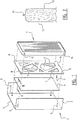
- Figure 1 shows a part of a housing 1 of the heating device according to the invention which consists of a rear wall 2 and two side walls 3. Formed together with a front wall, upper wall and lower wall (which are not shown here) is a closed cabinet in which components of the heating device are accommodated. Only heat exchanger 11 is shown here for the sake of clarity, although a heating module, a control unit and all the required conduits are of course also accommodated in the cabinet.
- an insulating panel 4 is arranged against rear wall 2 in order to increase the energy efficiency of the heating device.
- This insulating panel 4 comprises a core material 12 enclosed by a foil 13 which is joined together at a seam 14 to form a gas and water vapour-tight packaging.
- a vacuum is created in the volume of this packaging, whereby the heat conduction of core material 12 is greatly reduced and the insulating action thus greatly increased.
- Core material 12 can otherwise be formed by a pressed powder consisting substantially of microporous silicic acid. Cloaking means can also be present for the purpose of minimizing the infrared radiation, as well as cellulose fibres for improving the mechanical stability.
- plastic foil 13 is a reflective foil. Because the vacuum-packed core material 12 insulates so well, panel 4 can have a small thickness of a maximum of several tens of millimetres. A panel with a thickness in the order of a centimetre can probably suffice in practice.
- a spacer 5 is arranged between heat exchanger 11 and panel 4.
- This spacer 5 takes the form of a plate 6 in which a number of relatively large openings 7 have been formed, so that the spacer forms no obstruction to the heat radiation coming from heat exchanger 11 and reflected by the reflective foil 13 of panel 4.
- the plate 6 forming the spacer 5 can have a considerably greater thickness than vacuum panel 4; the thickness of plate 6 can be three to eight times that of panel 4. In the shown embodiment spacer 5 is about five times as thick as panel 4.
- Heat exchanger 11 is fixed to rear wall 2 by means of bolts 9 which are arranged on the rear wall and which protrude through eyes 10 on the edge of heat exchanger 11. Openings 8 through which bolts 9 pass are also formed in spacer 5.
- the dimensions of vacuum panel 4 are chosen such that it fits within the bolts 9. Panel 4 is simply enclosed here between wall 2 and spacer 5 so that no special provisions are required for fixing thereof.
- spacer can also be applied instead of the shown plate-like spacer 5 with large openings 7.
- the spacers are formed by simple bushings 15 round the bolts 9 with which heat exchanger 11 is fixed to rear wall 2.
- Special provisions are indeed necessary here to fix vacuum panel 4 to rear wall 2.
- this can for instance be realized by applying an adhesive layer 16 between panel 4 and wall 2.
- special clamping brackets 17 for fixing purposes. What is important here is that the fixing is such that foil 13 is not pierced, since the insulating power of vacuum panel 4 would then be greatly reduced.
- the application of an insulating material on the basis of a vacuum-packed core material thus makes it possible to reduce the losses of a heating device, particularly when it is not operational.
- the Energy Performance Coefficient of a building in which the heating device is applied can hereby be reduced.
- comfort is hereby increased since the heating device more readily remains at temperature during standstill and can thereby bring the water more quickly to a desired temperature after being switched on.
- the vacuum-packed insulating material could thus also be applied at other locations in the heating device. It is possible here to envisage the side walls, the upper and lower wall and parts of the front wall of the housing. The only practical limitation is that it is difficult to form passages through the vacuum-packed insulating material, so that it will not be possible to insulate parts of the housing.
Landscapes
- Engineering & Computer Science (AREA)
- General Engineering & Computer Science (AREA)
- Thermal Sciences (AREA)
- Mechanical Engineering (AREA)
- Physics & Mathematics (AREA)
- Chemical & Material Sciences (AREA)
- Combustion & Propulsion (AREA)
- Thermal Insulation (AREA)
- Details Of Fluid Heaters (AREA)
- Steam Or Hot-Water Central Heating Systems (AREA)
- Heat-Exchange Devices With Radiators And Conduit Assemblies (AREA)
- Instantaneous Water Boilers, Portable Hot-Water Supply Apparatuses, And Control Of Portable Hot-Water Supply Apparatuses (AREA)
- Muffle Furnaces And Rotary Kilns (AREA)
Claims (4)
- Dispositif, comprenant :- un échangeur de chaleur (11) qui est au moins partiellement enfermé par un matériau isolant (4) ;- dans lequel le matériau isolant comprend un matériau central emballé sous vide (12) ; dans lequel l'échangeur de chaleur (11) est reçu dans un logement (1) avec un certain nombre de parois (2, 3), dans lequel le matériau central emballé sous vide (12) est agencé entre au moins l'une des parois (2, 3) et l'échangeur de chaleur (11) ;- dans lequel le matériau central emballé sous vide (12) est réalisé comme un panneau (4), et ce panneau à vide (4) est agencé le long d'au moins l'une des parois ;caractérisé en ce que- le dispositif est un dispositif de chauffage configuré pour chauffer un milieu en écoulement comme l'eau, comprenant en outre un module de chauffage qui est au moins partiellement enfermé par un matériau isolant (4) ;- dans lequel le dispositif de chauffage est configuré pour chauffer le milieu en écoulement utilisé pour chauffer un espace ou approprié pour chauffer l'eau du robinet en utilisant la chaleur provenant du module de chauffage ;- dans lequel le matériau central emballé sous vide (12) est agencé à une certaine distance du module de chauffage et de l'échangeur de chaleur (11) à la fois ;- dans lequel le module de chauffage est reçu dans le logement (1) avec le certain nombre de parois (2, 3), dans lequel le matériau central emballé sous vide (12) est agencé entre au moins l'une des parois (2, 3) et le module de chauffage ;- dans lequel au moins une entretoise (5, 6, 9, 15) est agencée entre le module de chauffage et l'échangeur de chaleur (11) d'un côté et l'au moins un panneau à vide (4) de l'autre côté pour maintenir la distance ;- dans lequel le module de chauffage et/ou l'échangeur de chaleur (11) est/sont fixé(s) avec des boulons (9) à la paroi (2) du logement (1) ; et- dans lequel le panneau à vide (4) s'ajuste dans les boulons (9), enfermant le panneau à vide (4) entre la paroi (2) et l'entretoise (5, 6, 9, 15).
- Dispositif de chauffage selon la revendication 1, caractérisé en ce que le panneau à vide (4) est agencé le long d'une paroi sensiblement fermée du logement.
- Dispositif de chauffage selon la revendication 1 ou 2, caractérisé en ce que l'au moins un panneau à vide (4) comprend une feuille réfléchissante (13) enfermant le matériau central, et l'au moins une entretoise (5, 6, 9, 15) est sensiblement perméable au rayonnement.
- Dispositif de chauffage selon la revendication 3, caractérisé en ce que l'au moins une entretoise (5, 6, 9, 15) comprend une plaque (6) avec un certain nombre d'ouvertures (7).
Priority Applications (1)
| Application Number | Priority Date | Filing Date | Title |
|---|---|---|---|
| PL13710586T PL2809998T3 (pl) | 2012-02-03 | 2013-02-04 | Urządzenie ogrzewcze |
Applications Claiming Priority (2)
| Application Number | Priority Date | Filing Date | Title |
|---|---|---|---|
| NL2008225A NL2008225C2 (nl) | 2012-02-03 | 2012-02-03 | Verwarmingsinrichting. |
| PCT/NL2013/050057 WO2013115648A2 (fr) | 2012-02-03 | 2013-02-04 | Dispositif de chauffage |
Publications (2)
| Publication Number | Publication Date |
|---|---|
| EP2809998A2 EP2809998A2 (fr) | 2014-12-10 |
| EP2809998B1 true EP2809998B1 (fr) | 2019-08-21 |
Family
ID=47901262
Family Applications (1)
| Application Number | Title | Priority Date | Filing Date |
|---|---|---|---|
| EP13710586.2A Active EP2809998B1 (fr) | 2012-02-03 | 2013-02-04 | Dispositif de chauffage |
Country Status (12)
| Country | Link |
|---|---|
| US (1) | US20150020756A1 (fr) |
| EP (1) | EP2809998B1 (fr) |
| JP (1) | JP6199317B2 (fr) |
| KR (1) | KR102116260B1 (fr) |
| CA (1) | CA2855970C (fr) |
| ES (1) | ES2753992T3 (fr) |
| NL (1) | NL2008225C2 (fr) |
| PL (1) | PL2809998T3 (fr) |
| PT (1) | PT2809998T (fr) |
| RU (1) | RU2608404C2 (fr) |
| UA (1) | UA114308C2 (fr) |
| WO (1) | WO2013115648A2 (fr) |
Families Citing this family (2)
| Publication number | Priority date | Publication date | Assignee | Title |
|---|---|---|---|---|
| DK178708B1 (en) * | 2015-11-23 | 2016-11-28 | Ribe Jern Holding As | Radiator and radiator device |
| DE202017006747U1 (de) * | 2017-11-30 | 2018-05-17 | Robert Bosch Gmbh | Bauteil zur Anbindung einer Hydraulikeinheit einer Heizvorrichtung |
Family Cites Families (24)
| Publication number | Priority date | Publication date | Assignee | Title |
|---|---|---|---|---|
| US2189490A (en) * | 1938-06-17 | 1940-02-06 | David M Hart | Water heater |
| US2324710A (en) * | 1942-04-06 | 1943-07-20 | Chrysler Corp | Wall panel for furnace jackets or the like |
| US2749887A (en) * | 1955-03-28 | 1956-06-12 | Gustav E Olsen | Welded water wall boiler |
| BE795261A (fr) * | 1972-02-10 | 1973-05-29 | Bailey Frank W | Bruleurs canon a retention de flamme bleue et systemes d'echangeur de chaleur |
| NL158917B (nl) * | 1973-06-21 | 1978-12-15 | Beondu Ag | Ketelelement. |
| US3969051A (en) * | 1975-06-13 | 1976-07-13 | D.G. Rung Industries, Inc. | Vulcanizing apparatus |
| US4383575A (en) * | 1981-05-04 | 1983-05-17 | The Stanley Works | Baseboard heat reflector |
| US4676199A (en) * | 1986-04-07 | 1987-06-30 | Rheem Manufacturing Company | High efficiency water heater construction |
| US5315938A (en) * | 1987-03-24 | 1994-05-31 | Walter Freller | Heat accumulator |
| US4848450A (en) * | 1988-02-09 | 1989-07-18 | C & J Jones (1985) Limited | Heat exchanger |
| US5255969A (en) * | 1991-02-28 | 1993-10-26 | Rheem Manufacturing Company | Double-walled cabinet structure for air conditioning equipment |
| CA2302333A1 (fr) * | 2000-03-07 | 2001-09-07 | L. Paul Hebert | Convecteur de recuperation de chaleur installe apres coup |
| IT1318100B1 (it) * | 2000-06-30 | 2003-07-23 | Getters Spa | Pannello evacuato per isolamento termico di un corpo avente superficinon piane |
| JP2003014382A (ja) * | 2001-07-02 | 2003-01-15 | Sanyo Electric Co Ltd | 熱交換器及びヒートポンプ式給湯機 |
| JP3995990B2 (ja) * | 2002-06-03 | 2007-10-24 | 松下冷機株式会社 | 真空断熱材の保持具と真空断熱材の取付方法 |
| JP2005076966A (ja) * | 2003-08-29 | 2005-03-24 | Sanyo Electric Co Ltd | 冷却貯蔵庫 |
| JP2005221088A (ja) * | 2004-02-03 | 2005-08-18 | Matsushita Electric Ind Co Ltd | ヒートポンプ給湯機 |
| JP2008045580A (ja) * | 2006-08-11 | 2008-02-28 | Hitachi Appliances Inc | 真空断熱パネル及びそれを備えた機器 |
| JP5422953B2 (ja) * | 2007-11-12 | 2014-02-19 | ダイキン工業株式会社 | 空気調和機用室内機 |
| JP2010032175A (ja) * | 2008-07-31 | 2010-02-12 | Hitachi Appliances Inc | ヒートポンプ給湯機 |
| US9074716B2 (en) * | 2008-12-26 | 2015-07-07 | Mitsubishi Electric Corporation | Vacuum heat insulating material, heat insulating box using vacuum heat insulating material, refrigerator, refrigerating/air-conditioning apparatus, water heater, equipments, and manufacturing method of vacuum heat insulating material |
| JP2010243118A (ja) * | 2009-04-09 | 2010-10-28 | Toyota Industries Corp | 蓄熱装置及び車両用空調装置 |
| DE102010031250A1 (de) * | 2010-07-12 | 2012-01-12 | BSH Bosch und Siemens Hausgeräte GmbH | Gehäusekomponente für ein Kältegerät |
| DE102011075388A1 (de) * | 2011-05-06 | 2012-11-08 | BSH Bosch und Siemens Hausgeräte GmbH | Kältegerät, insbesondere Haushaltskältegerät |
-
2012
- 2012-02-03 NL NL2008225A patent/NL2008225C2/nl not_active IP Right Cessation
-
2013
- 2013-02-04 UA UAA201408654A patent/UA114308C2/uk unknown
- 2013-02-04 CA CA2855970A patent/CA2855970C/fr active Active
- 2013-02-04 KR KR1020147015455A patent/KR102116260B1/ko not_active Expired - Fee Related
- 2013-02-04 US US14/376,073 patent/US20150020756A1/en not_active Abandoned
- 2013-02-04 EP EP13710586.2A patent/EP2809998B1/fr active Active
- 2013-02-04 WO PCT/NL2013/050057 patent/WO2013115648A2/fr not_active Ceased
- 2013-02-04 JP JP2014555518A patent/JP6199317B2/ja not_active Expired - Fee Related
- 2013-02-04 ES ES13710586T patent/ES2753992T3/es active Active
- 2013-02-04 PL PL13710586T patent/PL2809998T3/pl unknown
- 2013-02-04 RU RU2014130597A patent/RU2608404C2/ru active
- 2013-02-04 PT PT137105862T patent/PT2809998T/pt unknown
Non-Patent Citations (1)
| Title |
|---|
| None * |
Also Published As
| Publication number | Publication date |
|---|---|
| PL2809998T3 (pl) | 2020-02-28 |
| CA2855970A1 (fr) | 2013-08-08 |
| WO2013115648A3 (fr) | 2014-09-12 |
| ES2753992T3 (es) | 2020-04-15 |
| WO2013115648A2 (fr) | 2013-08-08 |
| KR102116260B1 (ko) | 2020-06-08 |
| US20150020756A1 (en) | 2015-01-22 |
| NL2008225C2 (nl) | 2013-08-06 |
| RU2014130597A (ru) | 2016-03-27 |
| RU2608404C2 (ru) | 2017-01-18 |
| UA114308C2 (uk) | 2017-05-25 |
| JP2015512024A (ja) | 2015-04-23 |
| CA2855970C (fr) | 2020-12-15 |
| EP2809998A2 (fr) | 2014-12-10 |
| JP6199317B2 (ja) | 2017-09-20 |
| KR20140128291A (ko) | 2014-11-05 |
| PT2809998T (pt) | 2019-10-31 |
Similar Documents
| Publication | Publication Date | Title |
|---|---|---|
| CA2717853A1 (fr) | Dispositif d'aborption ou de dissipation de chaleur par fluide a difference de temperature en tuyauterie a double spirale | |
| CN101957078A (zh) | 平板型太阳能热水热风联供装置 | |
| CN102087050A (zh) | 一种太阳能热水热风联供装置 | |
| EP2809998B1 (fr) | Dispositif de chauffage | |
| WO2009013341A3 (fr) | Dispositif de production et d'exploitation de la chaleur solaire | |
| CN201021850Y (zh) | 家用太阳能灶具 | |
| CN202057024U (zh) | 一种储水式电磁热水器 | |
| EP3710757B1 (fr) | Système de climatisation pourvu d'un ensemble d'isolation | |
| CN202145020U (zh) | 一种高散热效率的电暖器 | |
| CN211267141U (zh) | 一种铝塑板加工用带有散热功能的加热辊 | |
| CN213014737U (zh) | 装配式建筑保温结构装置 | |
| GB2582887A (en) | A heating panel | |
| CN205481847U (zh) | 一种幕墙式太阳能集热器 | |
| RU126548U1 (ru) | Электрообогреватель | |
| CN203933978U (zh) | 一种表面不带电型ptc发热器 | |
| TWM366659U (en) | Energy storage-type solar water heater | |
| CN201827948U (zh) | 纤维水泥散热板 | |
| CN201368532Y (zh) | 一种充油式电暖器 | |
| CN211316538U (zh) | 一种家用整体式空气能热水器 | |
| CN201000133Y (zh) | 内嵌式碳纤维电暖器 | |
| CN105757767B (zh) | 一种陶瓷恒温散热器的制造方法 | |
| CN206212475U (zh) | 一种网络设备低温自动防护箱 | |
| CA2938908A1 (fr) | Radiateur emettant de la chaleur prolongee | |
| CN103335414A (zh) | 一种壁挂式太阳能开水锅炉 | |
| CN204438310U (zh) | 一种太阳能保温阳台 |
Legal Events
| Date | Code | Title | Description |
|---|---|---|---|
| PUAI | Public reference made under article 153(3) epc to a published international application that has entered the european phase |
Free format text: ORIGINAL CODE: 0009012 |
|
| 17P | Request for examination filed |
Effective date: 20140625 |
|
| AK | Designated contracting states |
Kind code of ref document: A2 Designated state(s): AL AT BE BG CH CY CZ DE DK EE ES FI FR GB GR HR HU IE IS IT LI LT LU LV MC MK MT NL NO PL PT RO RS SE SI SK SM TR |
|
| AX | Request for extension of the european patent |
Extension state: BA ME |
|
| DAX | Request for extension of the european patent (deleted) | ||
| 17Q | First examination report despatched |
Effective date: 20160406 |
|
| STAA | Information on the status of an ep patent application or granted ep patent |
Free format text: STATUS: EXAMINATION IS IN PROGRESS |
|
| GRAP | Despatch of communication of intention to grant a patent |
Free format text: ORIGINAL CODE: EPIDOSNIGR1 |
|
| STAA | Information on the status of an ep patent application or granted ep patent |
Free format text: STATUS: GRANT OF PATENT IS INTENDED |
|
| INTG | Intention to grant announced |
Effective date: 20190417 |
|
| GRAS | Grant fee paid |
Free format text: ORIGINAL CODE: EPIDOSNIGR3 |
|
| GRAA | (expected) grant |
Free format text: ORIGINAL CODE: 0009210 |
|
| STAA | Information on the status of an ep patent application or granted ep patent |
Free format text: STATUS: THE PATENT HAS BEEN GRANTED |
|
| AK | Designated contracting states |
Kind code of ref document: B1 Designated state(s): AL AT BE BG CH CY CZ DE DK EE ES FI FR GB GR HR HU IE IS IT LI LT LU LV MC MK MT NL NO PL PT RO RS SE SI SK SM TR |
|
| REG | Reference to a national code |
Ref country code: GB Ref legal event code: FG4D |
|
| REG | Reference to a national code |
Ref country code: CH Ref legal event code: EP |
|
| REG | Reference to a national code |
Ref country code: DE Ref legal event code: R096 Ref document number: 602013059425 Country of ref document: DE |
|
| REG | Reference to a national code |
Ref country code: AT Ref legal event code: REF Ref document number: 1170213 Country of ref document: AT Kind code of ref document: T Effective date: 20190915 |
|
| REG | Reference to a national code |
Ref country code: IE Ref legal event code: FG4D |
|
| REG | Reference to a national code |
Ref country code: NL Ref legal event code: FP |
|
| REG | Reference to a national code |
Ref country code: CH Ref legal event code: NV Representative=s name: ARNOLD AND SIEDSMA AG, CH |
|
| REG | Reference to a national code |
Ref country code: PT Ref legal event code: SC4A Ref document number: 2809998 Country of ref document: PT Date of ref document: 20191031 Kind code of ref document: T Free format text: AVAILABILITY OF NATIONAL TRANSLATION Effective date: 20191022 |
|
| REG | Reference to a national code |
Ref country code: RO Ref legal event code: EPE |
|
| REG | Reference to a national code |
Ref country code: SK Ref legal event code: T3 Ref document number: E 32338 Country of ref document: SK |
|
| REG | Reference to a national code |
Ref country code: LT Ref legal event code: MG4D |
|
| PG25 | Lapsed in a contracting state [announced via postgrant information from national office to epo] |
Ref country code: FI Free format text: LAPSE BECAUSE OF FAILURE TO SUBMIT A TRANSLATION OF THE DESCRIPTION OR TO PAY THE FEE WITHIN THE PRESCRIBED TIME-LIMIT Effective date: 20190821 Ref country code: HR Free format text: LAPSE BECAUSE OF FAILURE TO SUBMIT A TRANSLATION OF THE DESCRIPTION OR TO PAY THE FEE WITHIN THE PRESCRIBED TIME-LIMIT Effective date: 20190821 Ref country code: SE Free format text: LAPSE BECAUSE OF FAILURE TO SUBMIT A TRANSLATION OF THE DESCRIPTION OR TO PAY THE FEE WITHIN THE PRESCRIBED TIME-LIMIT Effective date: 20190821 Ref country code: BG Free format text: LAPSE BECAUSE OF FAILURE TO SUBMIT A TRANSLATION OF THE DESCRIPTION OR TO PAY THE FEE WITHIN THE PRESCRIBED TIME-LIMIT Effective date: 20191121 Ref country code: LT Free format text: LAPSE BECAUSE OF FAILURE TO SUBMIT A TRANSLATION OF THE DESCRIPTION OR TO PAY THE FEE WITHIN THE PRESCRIBED TIME-LIMIT Effective date: 20190821 Ref country code: NO Free format text: LAPSE BECAUSE OF FAILURE TO SUBMIT A TRANSLATION OF THE DESCRIPTION OR TO PAY THE FEE WITHIN THE PRESCRIBED TIME-LIMIT Effective date: 20191121 |
|
| PG25 | Lapsed in a contracting state [announced via postgrant information from national office to epo] |
Ref country code: LV Free format text: LAPSE BECAUSE OF FAILURE TO SUBMIT A TRANSLATION OF THE DESCRIPTION OR TO PAY THE FEE WITHIN THE PRESCRIBED TIME-LIMIT Effective date: 20190821 Ref country code: AL Free format text: LAPSE BECAUSE OF FAILURE TO SUBMIT A TRANSLATION OF THE DESCRIPTION OR TO PAY THE FEE WITHIN THE PRESCRIBED TIME-LIMIT Effective date: 20190821 Ref country code: RS Free format text: LAPSE BECAUSE OF FAILURE TO SUBMIT A TRANSLATION OF THE DESCRIPTION OR TO PAY THE FEE WITHIN THE PRESCRIBED TIME-LIMIT Effective date: 20190821 Ref country code: IS Free format text: LAPSE BECAUSE OF FAILURE TO SUBMIT A TRANSLATION OF THE DESCRIPTION OR TO PAY THE FEE WITHIN THE PRESCRIBED TIME-LIMIT Effective date: 20191221 Ref country code: GR Free format text: LAPSE BECAUSE OF FAILURE TO SUBMIT A TRANSLATION OF THE DESCRIPTION OR TO PAY THE FEE WITHIN THE PRESCRIBED TIME-LIMIT Effective date: 20191122 |
|
| PG25 | Lapsed in a contracting state [announced via postgrant information from national office to epo] |
Ref country code: TR Free format text: LAPSE BECAUSE OF FAILURE TO SUBMIT A TRANSLATION OF THE DESCRIPTION OR TO PAY THE FEE WITHIN THE PRESCRIBED TIME-LIMIT Effective date: 20190821 |
|
| REG | Reference to a national code |
Ref country code: ES Ref legal event code: FG2A Ref document number: 2753992 Country of ref document: ES Kind code of ref document: T3 Effective date: 20200415 |
|
| PG25 | Lapsed in a contracting state [announced via postgrant information from national office to epo] |
Ref country code: EE Free format text: LAPSE BECAUSE OF FAILURE TO SUBMIT A TRANSLATION OF THE DESCRIPTION OR TO PAY THE FEE WITHIN THE PRESCRIBED TIME-LIMIT Effective date: 20190821 Ref country code: DK Free format text: LAPSE BECAUSE OF FAILURE TO SUBMIT A TRANSLATION OF THE DESCRIPTION OR TO PAY THE FEE WITHIN THE PRESCRIBED TIME-LIMIT Effective date: 20190821 |
|
| PG25 | Lapsed in a contracting state [announced via postgrant information from national office to epo] |
Ref country code: SM Free format text: LAPSE BECAUSE OF FAILURE TO SUBMIT A TRANSLATION OF THE DESCRIPTION OR TO PAY THE FEE WITHIN THE PRESCRIBED TIME-LIMIT Effective date: 20190821 Ref country code: IS Free format text: LAPSE BECAUSE OF FAILURE TO SUBMIT A TRANSLATION OF THE DESCRIPTION OR TO PAY THE FEE WITHIN THE PRESCRIBED TIME-LIMIT Effective date: 20200224 |
|
| REG | Reference to a national code |
Ref country code: DE Ref legal event code: R097 Ref document number: 602013059425 Country of ref document: DE |
|
| PLBE | No opposition filed within time limit |
Free format text: ORIGINAL CODE: 0009261 |
|
| STAA | Information on the status of an ep patent application or granted ep patent |
Free format text: STATUS: NO OPPOSITION FILED WITHIN TIME LIMIT |
|
| PG2D | Information on lapse in contracting state deleted |
Ref country code: IS |
|
| 26N | No opposition filed |
Effective date: 20200603 |
|
| PG25 | Lapsed in a contracting state [announced via postgrant information from national office to epo] |
Ref country code: SI Free format text: LAPSE BECAUSE OF FAILURE TO SUBMIT A TRANSLATION OF THE DESCRIPTION OR TO PAY THE FEE WITHIN THE PRESCRIBED TIME-LIMIT Effective date: 20190821 |
|
| PG25 | Lapsed in a contracting state [announced via postgrant information from national office to epo] |
Ref country code: MC Free format text: LAPSE BECAUSE OF FAILURE TO SUBMIT A TRANSLATION OF THE DESCRIPTION OR TO PAY THE FEE WITHIN THE PRESCRIBED TIME-LIMIT Effective date: 20190821 |
|
| REG | Reference to a national code |
Ref country code: AT Ref legal event code: UEP Ref document number: 1170213 Country of ref document: AT Kind code of ref document: T Effective date: 20190821 |
|
| PG25 | Lapsed in a contracting state [announced via postgrant information from national office to epo] |
Ref country code: MT Free format text: LAPSE BECAUSE OF FAILURE TO SUBMIT A TRANSLATION OF THE DESCRIPTION OR TO PAY THE FEE WITHIN THE PRESCRIBED TIME-LIMIT Effective date: 20190821 Ref country code: CY Free format text: LAPSE BECAUSE OF FAILURE TO SUBMIT A TRANSLATION OF THE DESCRIPTION OR TO PAY THE FEE WITHIN THE PRESCRIBED TIME-LIMIT Effective date: 20190821 |
|
| PG25 | Lapsed in a contracting state [announced via postgrant information from national office to epo] |
Ref country code: MK Free format text: LAPSE BECAUSE OF FAILURE TO SUBMIT A TRANSLATION OF THE DESCRIPTION OR TO PAY THE FEE WITHIN THE PRESCRIBED TIME-LIMIT Effective date: 20190821 |
|
| P01 | Opt-out of the competence of the unified patent court (upc) registered |
Effective date: 20230526 |
|
| PGFP | Annual fee paid to national office [announced via postgrant information from national office to epo] |
Ref country code: LU Payment date: 20240226 Year of fee payment: 12 |
|
| PGFP | Annual fee paid to national office [announced via postgrant information from national office to epo] |
Ref country code: IE Payment date: 20240220 Year of fee payment: 12 |
|
| PGFP | Annual fee paid to national office [announced via postgrant information from national office to epo] |
Ref country code: AT Payment date: 20240220 Year of fee payment: 12 |
|
| PGFP | Annual fee paid to national office [announced via postgrant information from national office to epo] |
Ref country code: CZ Payment date: 20240123 Year of fee payment: 12 Ref country code: CH Payment date: 20240301 Year of fee payment: 12 Ref country code: PT Payment date: 20240122 Year of fee payment: 12 Ref country code: SK Payment date: 20240123 Year of fee payment: 12 |
|
| PGFP | Annual fee paid to national office [announced via postgrant information from national office to epo] |
Ref country code: PL Payment date: 20240123 Year of fee payment: 12 Ref country code: FR Payment date: 20240226 Year of fee payment: 12 Ref country code: BE Payment date: 20240226 Year of fee payment: 12 |
|
| PGFP | Annual fee paid to national office [announced via postgrant information from national office to epo] |
Ref country code: RO Payment date: 20250130 Year of fee payment: 13 |
|
| REG | Reference to a national code |
Ref country code: SK Ref legal event code: MM4A Ref document number: E 32338 Country of ref document: SK Effective date: 20250204 |
|
| REG | Reference to a national code |
Ref country code: CH Ref legal event code: PL |
|
| PG25 | Lapsed in a contracting state [announced via postgrant information from national office to epo] |
Ref country code: PT Free format text: LAPSE BECAUSE OF NON-PAYMENT OF DUE FEES Effective date: 20250804 |
|
| PG25 | Lapsed in a contracting state [announced via postgrant information from national office to epo] |
Ref country code: LU Free format text: LAPSE BECAUSE OF NON-PAYMENT OF DUE FEES Effective date: 20250204 |
|
| REG | Reference to a national code |
Ref country code: AT Ref legal event code: MM01 Ref document number: 1170213 Country of ref document: AT Kind code of ref document: T Effective date: 20250204 |
|
| PG25 | Lapsed in a contracting state [announced via postgrant information from national office to epo] |
Ref country code: AT Free format text: LAPSE BECAUSE OF NON-PAYMENT OF DUE FEES Effective date: 20250204 |
|
| PG25 | Lapsed in a contracting state [announced via postgrant information from national office to epo] |
Ref country code: CH Free format text: LAPSE BECAUSE OF NON-PAYMENT OF DUE FEES Effective date: 20250228 |
|
| PG25 | Lapsed in a contracting state [announced via postgrant information from national office to epo] |
Ref country code: CZ Free format text: LAPSE BECAUSE OF NON-PAYMENT OF DUE FEES Effective date: 20250204 |
|
| PG25 | Lapsed in a contracting state [announced via postgrant information from national office to epo] |
Ref country code: SK Free format text: LAPSE BECAUSE OF NON-PAYMENT OF DUE FEES Effective date: 20250204 |
|
| REG | Reference to a national code |
Ref country code: BE Ref legal event code: MM Effective date: 20250228 |
|
| PG25 | Lapsed in a contracting state [announced via postgrant information from national office to epo] |
Ref country code: FR Free format text: LAPSE BECAUSE OF NON-PAYMENT OF DUE FEES Effective date: 20250228 |
|
| PG25 | Lapsed in a contracting state [announced via postgrant information from national office to epo] |
Ref country code: BE Free format text: LAPSE BECAUSE OF NON-PAYMENT OF DUE FEES Effective date: 20250228 |
|
| PG25 | Lapsed in a contracting state [announced via postgrant information from national office to epo] |
Ref country code: IE Free format text: LAPSE BECAUSE OF NON-PAYMENT OF DUE FEES Effective date: 20250204 |
|
| PG25 | Lapsed in a contracting state [announced via postgrant information from national office to epo] |
Ref country code: RO Free format text: LAPSE BECAUSE OF NON-PAYMENT OF DUE FEES Effective date: 20260204 |
|
| PGFP | Annual fee paid to national office [announced via postgrant information from national office to epo] |
Ref country code: NL Payment date: 20260218 Year of fee payment: 14 |
|
| PGFP | Annual fee paid to national office [announced via postgrant information from national office to epo] |
Ref country code: GB Payment date: 20260219 Year of fee payment: 14 |
|
| PGFP | Annual fee paid to national office [announced via postgrant information from national office to epo] |
Ref country code: ES Payment date: 20260319 Year of fee payment: 14 |
|
| PGFP | Annual fee paid to national office [announced via postgrant information from national office to epo] |
Ref country code: DE Payment date: 20260217 Year of fee payment: 14 |
|
| PGFP | Annual fee paid to national office [announced via postgrant information from national office to epo] |
Ref country code: IT Payment date: 20260227 Year of fee payment: 14 |