EP2810026B1 - Dispositif pour déterminer et/ou surveiller une variable de processus - Google Patents
Dispositif pour déterminer et/ou surveiller une variable de processus Download PDFInfo
- Publication number
- EP2810026B1 EP2810026B1 EP12813797.3A EP12813797A EP2810026B1 EP 2810026 B1 EP2810026 B1 EP 2810026B1 EP 12813797 A EP12813797 A EP 12813797A EP 2810026 B1 EP2810026 B1 EP 2810026B1
- Authority
- EP
- European Patent Office
- Prior art keywords
- piezoelectric
- unit
- drive
- cavity
- reception unit
- Prior art date
- Legal status (The legal status is an assumption and is not a legal conclusion. Google has not performed a legal analysis and makes no representation as to the accuracy of the status listed.)
- Active
Links
Images



Classifications
-
- G—PHYSICS
- G01—MEASURING; TESTING
- G01F—MEASURING VOLUME, VOLUME FLOW, MASS FLOW OR LIQUID LEVEL; METERING BY VOLUME
- G01F23/00—Indicating or measuring liquid level or level of fluent solid material, e.g. indicating in terms of volume or indicating by means of an alarm
- G01F23/22—Indicating or measuring liquid level or level of fluent solid material, e.g. indicating in terms of volume or indicating by means of an alarm by measuring physical variables, other than linear dimensions, pressure or weight, dependent on the level to be measured, e.g. by difference of heat transfer of steam or water
- G01F23/28—Indicating or measuring liquid level or level of fluent solid material, e.g. indicating in terms of volume or indicating by means of an alarm by measuring physical variables, other than linear dimensions, pressure or weight, dependent on the level to be measured, e.g. by difference of heat transfer of steam or water by measuring the variations of parameters of electromagnetic or acoustic waves applied directly to the liquid or fluent solid material
- G01F23/296—Acoustic waves
-
- G—PHYSICS
- G01—MEASURING; TESTING
- G01F—MEASURING VOLUME, VOLUME FLOW, MASS FLOW OR LIQUID LEVEL; METERING BY VOLUME
- G01F23/00—Indicating or measuring liquid level or level of fluent solid material, e.g. indicating in terms of volume or indicating by means of an alarm
- G01F23/22—Indicating or measuring liquid level or level of fluent solid material, e.g. indicating in terms of volume or indicating by means of an alarm by measuring physical variables, other than linear dimensions, pressure or weight, dependent on the level to be measured, e.g. by difference of heat transfer of steam or water
- G01F23/28—Indicating or measuring liquid level or level of fluent solid material, e.g. indicating in terms of volume or indicating by means of an alarm by measuring physical variables, other than linear dimensions, pressure or weight, dependent on the level to be measured, e.g. by difference of heat transfer of steam or water by measuring the variations of parameters of electromagnetic or acoustic waves applied directly to the liquid or fluent solid material
- G01F23/296—Acoustic waves
- G01F23/2966—Acoustic waves making use of acoustical resonance or standing waves
- G01F23/2967—Acoustic waves making use of acoustical resonance or standing waves for discrete levels
-
- G—PHYSICS
- G01—MEASURING; TESTING
- G01N—INVESTIGATING OR ANALYSING MATERIALS BY DETERMINING THEIR CHEMICAL OR PHYSICAL PROPERTIES
- G01N11/00—Investigating flow properties of materials, e.g. viscosity, plasticity; Analysing materials by determining flow properties
-
- G—PHYSICS
- G01—MEASURING; TESTING
- G01N—INVESTIGATING OR ANALYSING MATERIALS BY DETERMINING THEIR CHEMICAL OR PHYSICAL PROPERTIES
- G01N9/00—Investigating density or specific gravity of materials; Analysing materials by determining density or specific gravity
- G01N9/24—Investigating density or specific gravity of materials; Analysing materials by determining density or specific gravity by observing the transmission of wave or particle radiation through the material
-
- G—PHYSICS
- G01—MEASURING; TESTING
- G01N—INVESTIGATING OR ANALYSING MATERIALS BY DETERMINING THEIR CHEMICAL OR PHYSICAL PROPERTIES
- G01N11/00—Investigating flow properties of materials, e.g. viscosity, plasticity; Analysing materials by determining flow properties
- G01N11/10—Investigating flow properties of materials, e.g. viscosity, plasticity; Analysing materials by determining flow properties by moving a body within the material
- G01N11/16—Investigating flow properties of materials, e.g. viscosity, plasticity; Analysing materials by determining flow properties by moving a body within the material by measuring damping effect upon oscillatory body
-
- G—PHYSICS
- G01—MEASURING; TESTING
- G01N—INVESTIGATING OR ANALYSING MATERIALS BY DETERMINING THEIR CHEMICAL OR PHYSICAL PROPERTIES
- G01N11/00—Investigating flow properties of materials, e.g. viscosity, plasticity; Analysing materials by determining flow properties
- G01N2011/006—Determining flow properties indirectly by measuring other parameters of the system
- G01N2011/0073—Determining flow properties indirectly by measuring other parameters of the system acoustic properties
-
- G—PHYSICS
- G01—MEASURING; TESTING
- G01N—INVESTIGATING OR ANALYSING MATERIALS BY DETERMINING THEIR CHEMICAL OR PHYSICAL PROPERTIES
- G01N9/00—Investigating density or specific gravity of materials; Analysing materials by determining density or specific gravity
- G01N9/002—Investigating density or specific gravity of materials; Analysing materials by determining density or specific gravity using variation of the resonant frequency of an element vibrating in contact with the material submitted to analysis
Definitions
- the present invention relates to a device for determining and / or monitoring at least one process variable of a medium in a container, with an oscillatable unit for insertion into the container, with a housing, the oscillatable unit being connected to the housing such that the oscillatable unit closes the housing at the end, and at least one cavity is introduced into the oscillatable unit, which is accessible from an interior formed by the housing, with a drive / receiver unit for exciting the oscillatable unit to mechanical vibrations and for receiving the mechanical vibrations and Converting into an electrical received signal, and with a control / evaluation unit for regulating or controlling the vibration excitation and for evaluating the received signal in relation to the process variable.
- the process variable is, for example, the fill level of a bulk material or a liquid and / or the density and / or the viscosity of a liquid or gaseous medium.
- Vibronic measuring devices with an oscillatable unit that can be excited to mechanical vibrations are often used for level measurement, in particular for level detection.
- the vibratable unit is usually designed as a so-called tuning fork with two rods attached to a membrane, while both bulk forks and rods with only one rod are used as resonators for bulk materials.
- Piezoelectric or magnetoelectric drives which excite the vibratable unit at its resonance frequency, are mostly used for vibration excitation.
- the piezoelectric drive is attached to the back of the diaphragm in the case of tuning forks.
- the membrane is quite thin so that there is good vibration energy transfer between the resonator and the drive.
- the membrane is about 1 to 2 mm thick and its diameter is 1/2 inch to 1.5 inches. The stability of such membranes is limited at high process pressure and is typically below 10 MPa.
- the attachment of the piezoelectric drive and receiving elements is, however, relatively difficult to carry out here, since the piezoelectric elements are glued to the wall and are accurate have to be positioned.
- the exact positioning of the piezo elements plays an important role, since the piezo drive has to generate a bending deformation in the transition area between the tines and the membrane. In addition, such a drive is only efficient with metallic tuning forks.
- US 6 044 694 A discloses a flexural vibrator with a bimorph piezoelectric element which is embedded in a potting element.
- the object of the invention is to provide a device of the type mentioned, the drive of which has a high efficiency regardless of the material of the oscillatable unit.
- a device for determining and / or monitoring at least one process variable of a medium in a container with an oscillatable unit for introduction into the container, with a housing, the oscillatable unit being connected to the housing in this way, that the oscillatable unit closes the end of the housing and at least one cavity is introduced into the oscillatable unit, which is accessible from an interior formed by the housing, with a drive / receiver unit for exciting the oscillatable unit to mechanical vibrations and for receiving the mechanical vibrations and conversion into an electrical received signal, and with a control / evaluation unit for regulating or controlling the vibration excitation and for evaluating the received signal in relation to the process variable, wherein in the case of a tuning fork, the vibratable unit has a first rod-shaped or paddle-shaped element and a second rod-shaped or paddle-shaped element which are connected to one another via a base, a first cavity in a root region near the base and a root region near a base of the second element, a second cavity for receiving the drive
- the drive / receiver unit has one piezoelectric unit in the form of bimorph piezos in the case of a single rod or two in the case of an tuning fork.
- the non-positive coupling of the piezoelectric unit to the oscillatable unit is produced via the potting material with which the at least one cavity is filled.
- the piezoelectric unit comprises a first planar piezoelectric element and a second planar piezoelectric element, which are non-positively connected to each other with one side surface to form a contact surface, and which are polarized in the direction perpendicular to the contact surface, at least the each side surface of the piezoelectric elements facing away from the contact surface is provided with an electrode for the application of an excitation signal and for tapping the received signal.
- the connection between the two piezoelectric elements is preferably made by means of an adhesive or a solder, so that the two piezoelectric elements are connected to one another via an electrically conductive intermediate layer.
- the piezoelectric elements are polarized in opposite directions and the conductive intermediate layer is connected to the ground potential.
- the two piezoelectric elements carry out periodic deformations in phase opposition in the form of expansions and shrinkages.
- the intermediate layer is designed as a third electrode and the excitation signal is applied to the three electrodes in such a way that the two outer electrodes are at the same potential and the third electrode is at the opposite potential wearing. Bending forces arise in both variants of the piezoelectric unit.
- the drive / receiver unit has one piezoelectric unit in the case of a single rod or two piezoelectric units in the case of a tuning fork, each with a piezoelectric element and a passive element, wherein the piezoelectric element can be acted upon by an excitation signal, and the piezoelectric element is mechanically connected to the passive element such that the application of the excitation signal to the piezoelectric element leads to bending deformations of the piezoelectric unit.
- the passive element here consists of a non-piezoelectric material, for example a ceramic or a metal, and serves to convert the mechanical stresses that arise when the excitation signal is applied to the piezoelectric element into a bending deformation.
- the piezoelectric element is provided with an electrode on each of two opposite side surfaces and is homogeneously polarized.
- the opposite side surface which is preferably the side surface in contact with the passive element, is preferably at the ground potential of the control / evaluation unit.
- two regions of opposite polarization are formed and the active electrodes are applied or introduced on the same side surface, while the opposite side surface has a common electrode.
- the common electrode is preferably located on the side surface which is in contact with the passive element.
- the common electrode preferably forms a flowing mass, i.e. a mass isolated from the mass of the control / evaluation unit.
- At least the oscillatable unit is made of a plastic or a composite material made of plastic and glass fibers, glass beads, carbon fibers and / or ceramic powder.
- Such composite materials also referred to as filled plastics, are particularly well suited as a material for a device according to the invention due to their robustness, stability and high mechanical quality.
- the housing of the device is also made of a plastic.
- At least the oscillatable unit is made of a metal or a metal alloy, a ceramic, a glass or a composite material made of ceramic and glass or ceramic and metal.
- the oscillatable unit consists of an electrically conductive material
- at least one cover or coating made of an electrically insulating material is applied to the drive / receiver unit.
- at least the electrodes are covered with a plate, for example made of glass or ceramic, or with a coating, preferably made of glass or ceramic, coated.
- the piezoelectric unit can also be cast in an insulating material.
- the material is a mixture of epoxy resin and Corundum powder or glass beads. This material can also serve as a potting material for the cavity.
- An embodiment of the invention provides that the rigidity of the potting material with which the first, second or third cavity is filled essentially corresponds to the rigidity of the material of the oscillatable unit. This results in an optimal power transmission from the drive / receiver unit embedded in the potting material to the mechanically oscillatable unit.
- the potting material is selected accordingly such that its rigidity corresponds to the rigidity of the plastic from which the oscillatable unit is made. For example, this is the case for an adhesive.
- the potting material with which the first, second or third cavity is filled and / or the material with which the drive / receiving unit is coated consists essentially of epoxy resin, epoxy resin and corundum powder, epoxy resin and ceramic powder, epoxy resin and sand or from epoxy resin and glass beads or fibers.
- a composite material made from 30 to 60 percent by volume epoxy resin and 70 to 30 percent by volume corundum powder or glass beads is particularly suitable for the potting material.
- An advantageous embodiment associated with the configuration as a tuning fork provides that two piezoelectric units are applied to a plate, in particular a printed circuit board, and that the plate is designed in such a way and the piezoelectric units are arranged on the plate in such a way that the piezoelectric units in the first and second cavity can be introduced.
- the plate is preferably a flexible printed circuit board.
- the plate can also be a rigid printed circuit board, a plastic plate, a film or a sheet.
- the control / evaluation unit applies an excitation signal to the drive / reception unit such that the rod-shaped or paddle-shaped elements carry out bending vibrations in opposite directions.
- the two rod-shaped or paddle-shaped elements vibrate in the basic mode.
- the inner mass in the case of a single rod, is rod-shaped, and the third cavity with the drive / receiving unit is arranged in such a way that the inner mass and the hollow body carry out bending vibrations in the opposite direction.
- the assembly is preferably carried out in such a way that the cavities of the tuning fork or the cavity of the rod are filled with the potting material and the drive / receiving unit is inserted into the still liquid potting material. The potting material then hardens and the drive / receiver unit is fixed in the cavity. A cumbersome direct application, in particular gluing, of the drive / receiver unit to the wall of the cavities or the cavity is eliminated.
- the configuration or arrangement of the drive / receiver unit according to the invention is particularly suitable for measuring devices with an oscillatable unit made of a plastic.
- Fig. 1 shows a container 12 filled with a medium 11, the limit level of which is to be monitored.
- a measuring device 1 with an oscillatable unit 2 is introduced at a height into the wall of the container 12 which corresponds to the limit level to be monitored.
- the oscillatable unit 2 has two rod-shaped elements 21, 22, which can also be paddle-shaped, in particular when used in liquid or solid powder-like media, and protrude into the container 12, while the housing 10 remains outside the container 12.
- electronic components for controlling, regulating and / or evaluating the measurement are arranged in the housing 10.
- the oscillatable unit 2 executes mechanical vibrations with the resonance frequency, the two rod-shaped elements 21, 22 executing bending vibrations towards and away from each other. From a change in the oscillation frequency, a change in the ambient medium in which the oscillatable unit 2 oscillates, and thereby the reaching of the limit fill level to be monitored, can be detected.
- the density or the viscosity of a liquid can also be determined by means of the vibrations of the oscillatable unit 2 or a limit value for these process variables can be monitored by means of the measuring device 1.
- the oscillation is usually excited via a piezoelectric transducer unit, which is arranged on a rear side of a membrane facing away from the medium 11, on which the rod-shaped elements 21, 22 are molded.
- the transducer unit can be designed such that a single piezoelectric element or a bimorph element is used both as a transmitter and a receiver, or the transducer unit comprises a plurality of piezoelectric elements, which are each transmitters or receivers.
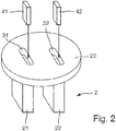
- the drive / receiver unit is not arranged on a membrane, but in pocket-like cavities in the rod-shaped elements 21, 22. This structure is shown in FIG Fig. 2 shown. Possible configurations of the drive / receiver unit 4 are shown in FIGS Figures 4a - 4e shown.
- Fig. 2 discloses a schematic view of an oscillatable unit 2 with a first rod-shaped element 21 and a second rod-shaped element 22, which are formed on a circular base 23.
- the rod-shaped elements 21, 22 are only shown schematically here.
- the rod-shaped elements 21, 22 preferably have a shape which is adapted to the area of application of the measuring device, for example a paddle shape known from the prior art for use in liquids or gases.
- the base 23 is preferably not designed as a membrane, but rather relatively thick.
- the thickness of the base 23 with a diameter of 1.5 inches is approximately 3-10 mm.
- the base 23 is thin, but the housing adjoining the base 23 is filled with a solid plastic at least in an area near the base 23.
- Two cavities 31, 32 are introduced into the base 23 and the rod-shaped elements 21, 22.
- the first cavity 31 extends into the root region of the first rod-shaped element 21 and the second cavity 32 extends accordingly into the root region of the second rod-shaped element 22. Except for the two cavities 31, 32, the rod-shaped elements 21, 22 are solid.
- Both cavities 31, 32 are accessible from the base 23, so that a first piezoelectric unit 41 can be introduced into the first cavity 31 and a second piezoelectric unit 42 into the second cavity 32.
- the two cavities 31, 32 are dimensioned such that the piezoelectric units 41, 42 are arranged at least in sections in the rod-shaped elements 21, 22 and in sections in the base 23.
- the piezoelectric units 41, 42 can also be arranged completely in the rod-shaped elements 21, 22.
- the two piezoelectric units 41, 42 form the drive / reception unit 4 of the tuning fork and each serve both to excite and to receive mechanical vibrations of the two rod-shaped elements 21, 22.
- the two flat side surfaces of the piezoelectric units 41, 42 are electrodes configured and in each case contactable with a connecting line, via which an excitation signal can be applied to the piezoelectric units 41, 42 and a received signal can be tapped from them.
- the piezoelectric units 41, 42 are each introduced into the cavities 31, 32 together with a suitable potting material.
- the potting material serves to fix the piezoelectric units 41, 42 and to transmit the bending deformations of the piezoelectric units 41, 42 to the rod-shaped elements 21, 22, so that the latter Carry out bending vibrations.
- the exact position of a piezoelectric unit 41, 42 in a cavity 31, 32 is irrelevant to the vibration excitation; the piezoelectric units 41, 42 can be aligned parallel to the side walls of the cavities 31, 32 or can also be inclined to the maximum. Since the piezoelectric units 41, 42 do not have to be positioned exactly and, moreover, cannot be fastened to a wall of the cavities 31, 32, the assembly is particularly simple.
- the installation of the piezoelectric units 41, 42 is Poka-Yoke-capable, that is to say, secure against installation errors.
- the first piezoelectric unit 41 is identical to the second piezoelectric unit 42, so that the two piezoelectric units 41, 42 can be arranged interchangeably in the first cavity 31 or the second cavity 32.
- a symmetrical configuration of the piezoelectric unit 41, 42 is possible, so that a rotation through 180 ° does not matter when it is introduced into the cavity 31, 32.
- a symmetrical configuration is, for example, in Fig. 4a shown.
- the potting material by means of which the piezoelectric units 41, 42 are cast into the cavities 31, 32 is, for example, an adhesive.
- the potting material is selected such that the mechanical stresses emanating from the piezoelectric units 41, 42 are effectively transmitted to the rod-shaped elements 21, 22.
- the rigidity of the potting material should correspond approximately to the rigidity of the material of the oscillatable unit 2.
- the oscillatable unit 2 consists of plastic, in particular a hard plastic.
- Composite materials are particularly suitable as the material for the oscillatable unit 2, for example filled or reinforced plastics which are reinforced with glass fibers, glass beads, ceramic powder or carbon fibers.
- An oscillatable unit 2 made of a plastic or a composite material is particularly easy and inexpensive to manufacture as an injection molded part.
- a material whose rigidity corresponds approximately to that of a plastic and is therefore suitable as a filler in a plastic version of the device or at least the oscillatable unit 2 is an epoxy resin, in particular an epoxy resin with a glass transition temperature of over 100 ° C.
- the oscillatable unit 2 is a ceramic part, which can be produced, for example, by means of CIM - Ceramic Injection Molding. Suitable ceramics are, for example, aluminum oxide, steatite, zirconium oxide, porcelain or silicon carbide. In yet other configurations, the oscillatable unit 2 consists of a glass, for example borosilicate glass or quartz glass, a glass ceramic or a composite of ceramic and glass particles or a composite of ceramic and metal particles.
- the drive shown can also be used in the case of conventional metallic oscillatable units 2.
- the piezoelectric units 41, 42 are provided with insulation in order to avoid a short circuit with the conductive wall of the cavities 31, 32.
- the potting material is preferably a solid adhesive which contains additives for reinforcement, for example in the form of corundum, silicon carbide or metal particles. A small distance between the wall of a cavity 31, 32 and the piezoelectric unit 41, 42 incorporated therein is also advantageous.
- the attachment of the drive / receiver unit 4 in the form of two piezoelectric units 41, 42 in cavities 31, 32 in the rod-shaped elements 21, 22 with fastening by means of potting leads to a very stable measuring device. Stability at high pressure loads is particularly important for tuning forks made of plastic, which are significantly more elastic than metals. Not only can the plastic break due to a pressure load, but the sensitive piezoceramic components can tear due to an elastic and plastic deformation in the plastic. If the piezoelectric drive / receiver unit 4 were arranged on a base configured as a membrane, as is often the case with metallic tuning forks, the membrane would have to be configured relatively thick.
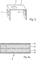
- Fig. 3 shows an electronics module, which after the assembly of the measuring device 1 with a vibratable unit 2 in the form of a fork Fig. 2 further simplified.
- Electronic components are arranged on a central section of a printed circuit board 6.
- the electronic components are used, for example, to generate the excitation signal and / or to evaluate the received signal in relation to the measured variable.
- a logic unit for example in the form of a microcontroller, is preferably also located below the electronic components.
- some parts of the electronics unit or also the entire electronics unit of the measuring device 1 can be arranged on the printed circuit board 6.
- a piezoelectric unit 41, 42 is located in each of the two edge regions of the printed circuit board 6 Fig. 4a arranged.
- the piezoelectric units 41, 42 are connected to the electronic components via conductor tracks on the printed circuit board 6.
- the piezoelectric units 41, 42 are applied to a metal sheet or a plastic plate instead of the printed circuit board 6.
- One advantage of the printed circuit board 6 is that one of the electrodes of a piezoelectric unit 41, 42 can be applied directly, for example by means of a conductive adhesive, to a metallic surface of the printed circuit board 6 and can therefore be contacted particularly easily.
- the edge regions of the printed circuit board 6 are angled or angled relative to the central section such that the two end regions with the piezoelectric units 41, 42 can be introduced into the two cavities 31, 32 in the rod-shaped elements 21, 22, while the central section outside the cavities 31, 32 remains.
- the potting located in the cavities 31, 32 fixes the two end regions of the printed circuit board 6 in the cavities 31, 32.
- the circuit board 6 is flexible or rigid. The integration of the piezoelectric units 41, 42 in a printed circuit board 6 to form an electronic module enables a particularly quick and secure attachment in the oscillatable unit 2.
- the Figures 4a to 4e illustrate various configurations of a piezoelectric unit 41.
- the drive / reception unit 4 of an oscillatable unit 2 in the form of an oscillating fork has at least two such piezoelectric units 41, 42, which are each introduced into a cavity 31, 32 of the rod-shaped elements 21, 22.
- the drive / reception unit 4 of a single rod preferably comprises only one such piezoelectric unit 41.
- Fig. 4a a cross section through a piezoelectric unit 41 designed as a bimorph piezo is shown.
- the piezoelectric unit 41 essentially consists of a first piezoelectric element 43 and a second piezoelectric element 44, each of which has a flat shape and is homogeneously polarized.
- a side surface of the first piezoelectric element 43 is fixedly and non-positively connected to a side surface of the second piezoelectric element 44, for example by means of an adhesive or solder.
- the electrode created as a contact surface is not subjected to a potential.
- the exposed side surfaces of the piezoelectric elements 43, 44 facing away from one another are each coated with an electrode 45, 46, or the electrodes 45, 46 are applied to the side surfaces.
- the electrodes 45, 46 can be produced, for example, by means of a construction adhesive, diffusion welding or electrode implementation in the piezoceramic - so-called cofired electrodes.
- the two piezoelectric elements 43, 44 are arranged relative to one another in such a way that their polarization direction is opposite.
- the direction of polarization is indicated in the figure by the arrows.
- the first electrode 45 and the second electrode 46 can each be contacted with a connection line for connection to a control / evaluation unit, which controls the application of an electrical excitation signal to the electrodes 45, 46 and receives an electrical reception signal from the piezoelectric unit 41 and is related evaluates to the process size.
- the first electrode 45 and the second electrode 46 are acted upon by an alternating voltage. This results in a series connection of the two piezoelectric elements 43, 44. Due to the opposite polarization direction of the piezo elements 43, 44, the first piezoelectric element 43 contracts when the piezoelectric element is acted on, while the second piezoelectric element 44 expands, and vice versa. Overall, the piezoelectric unit 41 performs a mutual bending deformation. The non-positive connection between the first piezoelectric element 43 and the second piezoelectric element 44 is important so that the piezoelectric unit 41 is bent as far as possible by means of the joined piezoelectric elements 43, 44.
- An advantage according to Fig. 4a configured piezoelectric unit 41 is that due to the polarity of the piezoelectric elements 43, 44 being the same at the location of the first electrodes 45 and at the location of the second electrode 46, no pyroelectric voltage arises even in the event of high temperature jumps, so-called temperature shocks.
- a measuring device with a drive / receiver unit 4 in the form of one or more such piezoelectric units 41, 42 is therefore particularly safe and suitable for use in explosion-protected areas.
- Fig. 4b is a variant of Fig. 4a shown, the two piezoelectric elements 43, 44 are also polarized in opposite directions.
- the two piezoelectric elements 43, 44 are not directly glued to one another, but are at least essentially congruently attached to opposite sides of a thin plate 6.
- it is a sheet metal or a printed circuit board.
- it is the one printed circuit board which has no insulation in the region of the piezoelectric elements 43, 44, so that the two side surfaces of the piezoelectric elements facing the plate 6 and provided with an electrode, for example in the form of an electrically conductive coating 43, 44 are in conductive contact with one another via the exposed metallic layer of the printed circuit board 6 and are at the same electrical potential.
- Fig. 4b The embodiment shown is especially for a module Fig. 3 suitable.
- Two piezoelectric elements 43, 44 are then respectively arranged in the two end regions of the printed circuit board 6 such that the printed circuit board 6 lies between them. In this configuration, too, no pyroelectric voltage occurs between the two electrodes 45, 46.
- Fig. 4c an embodiment is disclosed in which the polarization direction of the two piezoelectric elements 43, 44 coincides.
- the contact surface of the two piezoelectric elements 43, 44 is formed by a third electrode 47, which is for example in the form of a metallic coating. While the two outer electrodes 45, 46 are at the same potential when the excitation signal is applied, the third electrode 47 in the middle is on the opposite one Potential or to ground. When this is applied, the same mechanical stresses arise in the piezoelectric unit 41 as in the embodiment according to Fig. 4a so that the piezoelectric unit 41 experiences the same bending deformations. However, the deflection is higher than that in Fig.
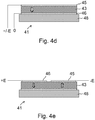
- Fig. 4d shows a variant of a piezoelectric unit 41 with only one homogeneously polarized piezoelectric element 43.
- the piezoelectric element 43 is attached to a passive element 48, for example with a side face by gluing or soldering.
- the passive element 48 is referred to as passive because it has no piezoelectric properties and is also not subjected to a voltage.
- the dimensions of the passive element 48 are preferably at least so large that the side surface of the piezoelectric element 43, which forms the contact surface, is completely in contact with the passive element 48.
- the material of the passive element 48 is selected such that its modulus of elasticity is similar to that of the piezoelectric material of the piezoelectric element 43 that is in firm contact with it.
- the passive element 48 is a disk made of a metal, such as steel, aluminum, titanium, bronze, brass or copper, or of a ceramic, such as aluminum oxide, porcelain or steatite.
- the exposed side surface of the piezoelectric element 43 and the contact surface are each provided with a metallic coating to form an electrode 45, 46.
- the electrodes 45, 46 can be acted upon by the excitation signal.
- FIG. 4e Another variant is shown with a non-piezoelectric passive element 48.
- a piezoelectric element 43 which has two regions of opposite polarization, is applied to the flat passive element 48.
- the direction of polarization is perpendicular to the contact surface between the piezoelectric element 43 and the passive element 48.
- the two regions are each provided on the exposed side surface of the piezoelectric element 43 with an electrode 45, 46 to which the excitation signal can be applied.
- the contact surface between piezoelectric element 43 and passive element 48 is designed as an inactive electrode, ie without being connected to a potential of the drive / receiver unit.
- Piezoelectric units 41 shown can be used in measuring devices 1 with an oscillatable unit 2 made of any material.
- the cavity 3, 31 has an electrically conductive wall.
- the insulation consists, for example, of a coating which is applied at least to the two electrodes 45, 46.
- the coating is, for example, a ceramic or a glass.
- the entire piezoelectric unit 41 is encased by an insulating layer. For example, such a coating can be produced by pouring the piezoelectric unit 41 into the insulation material.
- the electrodes 45, 46 are each covered with a plate made of an insulator. Glass or ceramic plates are particularly suitable for this. Highly filled adhesives with corundum particles or glass beads are also well suited as insulation material for the piezoelectric unit 41.
- An advantageous composition is 30-60 volume percent epoxy resin and 70-40 volume percent corundum powder or glass beads.
- Piezoelectric units 41 shown are poka-yoke capable. Faulty contacting by interchanging the connecting wires is excluded, as is faulty installation in the cavity 3, 31. This has a great advantage in the manufacture of the measuring devices according to the invention.
- a further advantage in production that arises in all of the configurations shown is that the piezoelectric unit 41 does not have to be aligned in an exact position and attached to another component of the oscillatable unit 2. Instead, the piezoelectric unit 41 can simply be cast or glued in the cavity 3, 31.
- the piezoelectric unit 41 can be prefabricated and equipped with connecting lines, so that only the finished component has to be assembled, which saves time and effort.
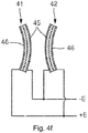
- Fig. 4f are two piezoelectric units 41, 42 according to Fig. 4a shown during the application of an AC voltage.
- the arrangement of the piezoelectric units 41, 42 corresponds to the assembled state in an oscillatable unit 2 Fig. 2 , ie a first piezoelectric unit 41 inserted into the first cavity 31 and a second piezoelectric unit 42 inserted into the second cavity 32.
- the mutually facing electrodes 45 of the two piezoelectric units 41, 42 are connected to the same potential -E.
- the two outer electrodes 46 are connected to the same potential + E.
- the outer electrodes 46 or the inner electrodes 45 can be connected to ground and the respective other electrodes can be connected to the potential +/- E.
- the first piezoelectric unit 41 and the second piezoelectric unit 42 are both curved inward in the loading shown, ie the smallest distance between the two piezoelectric units 41, 42 is between their centers.
- the two piezoelectric units 41, 42 are correspondingly curved in the other direction.
- the oscillatable unit 2 is excited to vibrate in the basic mode. In other words, the rod-shaped elements 21, 22 execute vibrations in the opposite direction.
- a great advantage of this arrangement and design of the drive / receiver unit 4 is the insensitivity to vibrations in asymmetrical modes, which can occur in the application due to external vibrations. These are not detected by the piezoelectric units 21, 22, i.e. Deflections of the rod-shaped elements 21, 22 in the axial or parallel to the direction perpendicular to the direction of vibration, as well as asymmetrical deflections in the direction of vibration do not generate a voltage signal in the piezoelectric elements 43, 44 of the piezoelectric units 41, 42.
- the measuring certainty of the measuring device 1 is subject to external vibrations therefore very high.
- the same also applies to the use of two piezoelectric units 41, 42 according to one of the other configurations shown.
- FIG. 5a and 5b Two different configurations of a measuring device with an oscillatable unit 2 in the form of a rod are shown in cross section.
- Such measuring devices also called single-rod, are often used in the level measurement of bulk materials and are manufactured and sold by the applicant under the name Soliphant.
- An advantageously designed one-rod is for example in the published patent application WO 2004/094964 A1 (or. US 2007/028691 A1 ) described.
- Another element is in US 5 670 709 A. disclosed.
- the oscillatable unit 2 consists of a tubular hollow body 7 and a rod-shaped inner mass 71.
- the inner mass 71 can also be shaped in a shape other than that of a solid rod.
- One end of the hollow body 7 is connected to a process connection 72, while the other end faces the process.
- the hollow body 7 and the inner mass 71 swing in opposite directions.
- Inner mass 71 and hollow body 7 are dimensioned and matched to one another in such a way that a corresponding counterforce acts for each force occurring due to the vibrations, so that essentially no forces act on the clamping and the vibration system is decoupled.
- the inner mass 71 is connected to the hollow body 7 in the process-oriented end region of the hollow body 7.
- the process-facing end region of the hollow body 7 is preferably closed with a cap to which the inner mass 71 is fastened, for example by means of a screw connection.
- the drive / receiver unit 4 for exciting the oscillatable unit 2 to flexural vibrations and for receiving the mechanical vibrations of the oscillatable unit 2 is introduced into a cavity 3 which is located in the inner mass 71.
- the cavity 3 is arranged near the fastening area of the inner mass 71 on the hollow body 7.
- the cavity 3 is designed as a slot and is only slightly larger than the drive / receiver unit 4 located in it; this is particularly the case when the oscillatable unit 2 is made of a metal.
- the electrical lines for contacting the drive / receiver unit 4 can be routed through the hollow body 7 and the process connection 72 to an electronic unit, not shown here, which is preferably arranged in a housing, also not shown.
- the housing can be fastened to the process connection 72 on the side facing away from the process.
- Fig. 5b shows an alternative embodiment of a single rod, the rod-shaped inner mass 71 and the tubular hollow body 7 being connected to one another in an end region of the hollow body 7 facing away from the process.
- the inner mass 71 is attached to a membrane, which is clamped in the process connection 72.
- the hollow body 7 is also in a fixed connection to the process connection 72, for example via a welded or screw connection.
- the cavity 3, in which the drive / receiver unit 4 is introduced, is located near the membrane in the inner mass 71.
- the drive / receiver unit 4 is preferably a bimorph piezo, ie a piezoelectric unit 41, as shown in FIG Fig. 4a or Fig. 4c is shown and described, or around a unimorph piezo, as in Fig. 4d or Fig. 4e shown.
- the drive / receiver unit 4 is preferably completely or at least coated with an insulating material in the region of the electrodes.
- the potting material with which the cavity 3 is potted to fix the drive / receiving unit 4 and to establish a non-positive connection with the wall of the cavity 3 is preferably a hard adhesive.
Landscapes
- Physics & Mathematics (AREA)
- General Physics & Mathematics (AREA)
- Acoustics & Sound (AREA)
- Electromagnetism (AREA)
- Thermal Sciences (AREA)
- Fluid Mechanics (AREA)
- Chemical & Material Sciences (AREA)
- Life Sciences & Earth Sciences (AREA)
- Health & Medical Sciences (AREA)
- Analytical Chemistry (AREA)
- Biochemistry (AREA)
- General Health & Medical Sciences (AREA)
- Immunology (AREA)
- Pathology (AREA)
- General Electrical Machinery Utilizing Piezoelectricity, Electrostriction Or Magnetostriction (AREA)
- Measurement Of Levels Of Liquids Or Fluent Solid Materials (AREA)
Claims (12)
- Dispositif (1) destiné à la détermination et/ou la surveillance d'au moins une grandeur process d'un produit (11) dans un réservoir (12), avec une unité apte à vibrer (2) destinée à être introduite dans le réservoir (12), avec un boîtier (10, l'unité apte à vibrer (2) étant reliée avec le boîtier (10) de telle sorte que l'unité apte à vibrer (2) ferme le boîtier (10) en son extrémité et au moins une cavité (3) étant réalisée dans l'unité apte à vibrer (2), laquelle cavité est accessible par un espace intérieur formé par le boîtier (10), avec une unité d'entraînement / de réception (4) destinée à exciter l'unité apte à vibrer (2) en vibrations mécaniques et destinée à la réception des vibrations mécaniques et à la conversion en un signal de réception électrique, et avec une unité de régulation / d'exploitation (5) destinée à la régulation ou à la commande de l'excitation en vibrations et destinée à l'exploitation du signal de réception par rapport à la grandeur de process,
dispositif pour lequel, dans le cas d'une fourche vibrante, l'unité apte à vibrer (2) présente un premier élément en forme de tige ou d'ailette (21) et un deuxième élément en forme de tige ou d'ailette (22), lesquels sont reliés entre eux par l'intermédiaire d'une base (23), une première cavité (31) étant réalisée dans une zone racinaire, proche de la base, du premier élément (21), et une deuxième cavité (32) étant réalisée dans une zone racinaire, proche de la base, du deuxième élément (22), destinées à la réception de l'unité d'entraînement / de réception (4), l'unité d'entraînement / de réception (4) comportant deux unités piézoélectriques (41, 42), les deux unités piézoélectriques (41, 42) de l'unité d'entraînement / de réception (4) étant introduites dans la première et la deuxième cavité (31, 32), et les deux cavités (31, 32) étant remplies avec un matériau de surmoulage, de telle sorte que l'unité d'entraînement / de réception (4) est reliée par friction à travers le matériau de surmoulage avec respectivement une paroi de la première et de la deuxième cavité (31, 32),
ou
dispositif pour lequel, dans le cas d'une monotige, l'unité apte à vibrer (2) est conçue en tant que corps creux (7) en forme de tige avec une masse intérieure (71) formée dans un intérieur du corps creux (7) sur une paroi du corps creux (7), l'unité d'entraînement / d'exploitation (4) comportant une unité piézoélectrique, l'unité d'entraînement / d'exploitation (4) étant introduite dans une troisième cavité (3) réalisée dans la masse intérieure (7), l'unité d'entraînement / d'exploitation (4) étant introduite dans la troisième cavité (3) et la troisième cavité (3) étant remplie d'un matériau de surmoulage, de telle sorte que l'unité d'entraînement / d'exploitation (4) est reliée par friction à travers le matériau de surmoulage avec une paroi de la troisième cavité (3). - Dispositif selon la revendication 1,
pour lequel l'unité d'entraînement / de réception (4) présente, dans le cas d'une monotige ou dans le cas d'une fourche vibrante, deux unités piézoélectriques (41, 42) sous la forme d'éléments piézoélectriques bimorphes. - Dispositif selon la revendication 2,
pour lequel l'unité piézoélectrique (41, 42) comprend un premier élément piézoélectrique plat (43) et un deuxième élément piézoélectrique plat (44), lesquels éléments sont reliés entre eux, au moyen d'une liaison par friction, avec respectivement une surface latérale en formant une surface de contact, et lesquels éléments sont polarisés selon une direction perpendiculaire à la surface de contact, la surface latérale - située à l'opposé de la surface de contact respective - des éléments piézoélectriques (43, 44) étant munie d'une électrode (45, 46) en vue de l'alimentation d'un signal d'excitation et du prélèvement du signal de réception. - Dispositif selon la revendication 1,
pour lequel l'unité d'entraînement / d'exploitation (4) présente, dans le cas d'une monotige, un, ou dans le cas d'une fourche vibrante, deux unités piézoélectriques avec respectivement un élément piézoélectrique (43) et respectivement un élément passif (48), l'élément piézoélectrique (43) pouvant être alimenté par un signal d'excitation, et l'élément piézoélectrique (43) étant relié mécaniquement avec l'élément passif (48) de telle sorte que l'alimentation de l'élément piézoélectrique (43) avec le signal d'excitation entraîne des déformations de flexion de l'unité piézoélectrique. - Dispositif selon l'une des revendications précédentes,
pour lequel au moins l'unité apte à vibrer (2) est fabriquée en un plastique ou en un matériau composite constitué de plastique et de fibres de verre, de billes de verre, de fibres de carbone et/ou de poudre de céramique. - Dispositif selon l'une des revendications 1 à 4,
pour lequel au moins l'unité apte à vibrer (2) est fabriquée en un métal ou un alliage métallique, une céramique, un verre ou un matériau composite en céramique et verre, ou céramique et métal. - Dispositif selon l'une des revendications précédentes,
pour lequel, dans le cas où l'unité apte à vibrer (2) est constituée d'un matériau électriquement conducteur, au moins un recouvrement ou un revêtement constitué d'un matériau électriquement conducteur est appliqué sur l'unité d'entraînement / d'exploitation (4). - Dispositif selon l'une des revendications précédentes,
pour lequel la rigidité du matériau de surmoulage, avec lequel la première, la deuxième ou la troisième cavité (3, 31, 32) est remplie, correspond pour l'essentiel à la rigidité du matériau de l'unité apte à vibrer (2). - Dispositif selon au moins l'une des revendications 7 et 8,
pour lequel le matériau de surmoulage, avec lequel la première, la deuxième ou la troisième cavité (3, 31, 32) sont remplies et/ou le matériau, avec lequel l'unité d'entraînement / d'exploitation (4) est revêtue, est constitué pour l'essentiel de résine époxy, de résine époxy et de poudre de corindon, de poudre de céramique ou de sable, ou de résine époxy et de billes de verre ou de fibres de verre. - Dispositif selon l'une des revendications précédentes,
pour lequel, dans le cas d'une fourche vibrante, deux unités piézoélectriques (41, 42) sont installées sur une platine (6), notamment une platine de circuit imprimé, la platine (6) étant conçue et les unités piézoélectriques (41, 42) étant disposées sur la platine (6) de telle sorte que les unités piézoélectriques (41, 42) puissent être introduites dans la première et la deuxième cavité (31, 32). - Dispositif selon la revendication 1 ou 10,
pour lequel, dans le cas de lames vibrantes, l'unité de régulation / d'exploitation alimente l'unité d'entraînement / de réception (4) avec un signal d'excitation de telle sorte que les éléments en forme de tige et d'ailette exécutent des vibrations de flexion en directions opposées. - Dispositif selon la revendication 1,
pour lequel, dans le cas d'une monotige, la masse intérieure (71) est en forme de tige, la troisième cavité (3) avec l'unité d'entraînement / de réception étant disposée de telle sorte que la masse intérieure (71) et la cavité (7) exécutent des vibrations de flexion en directions opposées.
Applications Claiming Priority (2)
| Application Number | Priority Date | Filing Date | Title |
|---|---|---|---|
| DE102012100728A DE102012100728A1 (de) | 2012-01-30 | 2012-01-30 | Vorrichtung zur Bestimmung und/oder Überwachung mindestens einer Prozessgröße |
| PCT/EP2012/075781 WO2013113446A1 (fr) | 2012-01-30 | 2012-12-17 | Dispositif pour déterminer et/ou surveiller au moins une grandeur de processus |
Publications (2)
| Publication Number | Publication Date |
|---|---|
| EP2810026A1 EP2810026A1 (fr) | 2014-12-10 |
| EP2810026B1 true EP2810026B1 (fr) | 2020-06-17 |
Family
ID=47557041
Family Applications (1)
| Application Number | Title | Priority Date | Filing Date |
|---|---|---|---|
| EP12813797.3A Active EP2810026B1 (fr) | 2012-01-30 | 2012-12-17 | Dispositif pour déterminer et/ou surveiller une variable de processus |
Country Status (5)
| Country | Link |
|---|---|
| US (1) | US10107670B2 (fr) |
| EP (1) | EP2810026B1 (fr) |
| CN (1) | CN104081171B (fr) |
| DE (1) | DE102012100728A1 (fr) |
| WO (1) | WO2013113446A1 (fr) |
Families Citing this family (30)
| Publication number | Priority date | Publication date | Assignee | Title |
|---|---|---|---|---|
| US9422944B2 (en) * | 2014-08-15 | 2016-08-23 | Dell Products, Lp | Carbon fiber laminate piezoelectric cooler and method therefor |
| DE102015102834A1 (de) * | 2015-02-27 | 2016-09-01 | Endress + Hauser Gmbh + Co. Kg | Vibronischer Sensor |
| DE102015114286A1 (de) * | 2015-08-27 | 2017-03-02 | Endress + Hauser Flowtec Ag | Vibronische Vorrichtung zur Bestimmung oder Überwachung einer Prozessgröße |
| US10281314B2 (en) * | 2016-03-30 | 2019-05-07 | Hella Kgaa Hueck & Co. | Device for measuring a fill level of a liquid |
| CN105932151B (zh) * | 2016-05-17 | 2018-11-09 | 湖北大学 | 用于粘度测试的微流控芯片及制作方法 |
| JP2017207409A (ja) * | 2016-05-20 | 2017-11-24 | 株式会社村田製作所 | 内容物検知装置 |
| EP3273210B1 (fr) * | 2016-07-18 | 2022-05-18 | VEGA Grieshaber KG | Détecteur de niveau à lames vibrantes et son procede de fabrication |
| DE102016118897B4 (de) * | 2016-10-05 | 2022-12-22 | Arianegroup Gmbh | Kryotauglicher Resonator-Sensor |
| DE102017130527A1 (de) | 2017-12-19 | 2019-06-19 | Endress+Hauser SE+Co. KG | Vibronischer Sensor |
| CN108471257B (zh) * | 2018-04-24 | 2019-07-16 | 哈尔滨工业大学 | 一种压电振动能量收集结构 |
| DE102018127526A1 (de) | 2018-11-05 | 2020-05-07 | Endress+Hauser SE+Co. KG | Vibronischer Multisensor |
| DE102019110821A1 (de) | 2019-04-26 | 2020-10-29 | Endress+Hauser SE+Co. KG | Vibronischer Multisensor |
| WO2020243682A1 (fr) * | 2019-05-30 | 2020-12-03 | Baker Hughes Oilfield Operations Llc | Mesure du niveau de solides au moyen de capteurs à tige vibrante |
| DE102019116150A1 (de) * | 2019-06-13 | 2020-12-17 | Endress+Hauser SE+Co. KG | Vibronischer Multisensor |
| DE102019116152A1 (de) * | 2019-06-13 | 2020-12-17 | Endress+Hauser SE+Co. KG | Vibronischer Multisensor |
| DE102019116151A1 (de) * | 2019-06-13 | 2020-12-17 | Endress+Hauser SE+Co. KG | Vibronischer Multisensor |
| DE102020104065A1 (de) | 2020-02-17 | 2021-08-19 | Endress+Hauser SE+Co. KG | Vibronischer Sensor mit reduzierter Anfälligkeit für Gasblasenbildung |
| DE102020104066A1 (de) | 2020-02-17 | 2021-08-19 | Endress+Hauser SE+Co. KG | Vibronischer Sensor |
| DE102020105214A1 (de) | 2020-02-27 | 2021-09-02 | Endress+Hauser SE+Co. KG | Vibronischer Multisensor |
| DE102020116278A1 (de) | 2020-06-19 | 2021-12-23 | Endress+Hauser SE+Co. KG | Vibronischer Multisensor |
| DE102020116299A1 (de) | 2020-06-19 | 2021-12-23 | Endress+Hauser SE+Co. KG | Symmetrierung eines vibronischen Sensors |
| DE102020121610A1 (de) | 2020-08-18 | 2022-02-24 | Vega Grieshaber Kg | Vibronischer Sensor und Verfahren zur Bestimmung einer Prozessgröße |
| DE102021122534A1 (de) | 2021-08-31 | 2023-03-02 | Endress+Hauser SE+Co. KG | Vibronischer Multisensor |
| DE102021122533A1 (de) | 2021-08-31 | 2023-03-02 | Endress+Hauser SE+Co. KG | Vibronischer Multisensor |
| DE102021126092A1 (de) | 2021-10-07 | 2023-04-13 | Endress+Hauser SE+Co. KG | Vibronischer Multisensor |
| DE102021126093A1 (de) | 2021-10-07 | 2023-04-13 | Endress+Hauser SE+Co. KG | Entkopplungseinheit für einen vibronischen Sensor |
| DE102022115594A1 (de) * | 2022-06-22 | 2023-12-28 | Endress+Hauser SE+Co. KG | Modularer vibronischer Multisensor |
| DE102022115591A1 (de) * | 2022-06-22 | 2023-12-28 | Endress+Hauser SE+Co. KG | Modularer vibronischer Multisensor |
| DE102022133730A1 (de) | 2022-12-16 | 2024-06-27 | Endress+Hauser SE+Co. KG | Vorrichtung zur Bestimmung und/oder Überwachung zumindest einer Prozessgröße eines Mediums |
| DE102023118598A1 (de) | 2023-07-13 | 2025-01-16 | Endress+Hauser SE+Co. KG | Vibrationssensor |
Citations (2)
| Publication number | Priority date | Publication date | Assignee | Title |
|---|---|---|---|---|
| EP0070334A1 (fr) * | 1981-07-17 | 1983-01-26 | The Marconi Company Limited | Appareil de mesure du niveau d'un liquide |
| US5670709A (en) * | 1992-12-12 | 1997-09-23 | Gallagher; John G. | Transducer for the measurement of attributes of flowable media |
Family Cites Families (19)
| Publication number | Priority date | Publication date | Assignee | Title |
|---|---|---|---|---|
| JPS5372650A (en) | 1976-12-09 | 1978-06-28 | Kkf Corp | Sensing apparatus |
| DE3067372D1 (en) * | 1979-10-29 | 1984-05-10 | Bestobell Uk Ltd | Liquid level sensor |
| GB8705757D0 (en) | 1987-03-11 | 1987-04-15 | Schlumberger Electronics Uk | Fluid transducer |
| GB8719105D0 (en) * | 1987-08-12 | 1987-09-16 | Schlumberger Electronics Uk | Fluid metering |
| US6044694A (en) * | 1996-08-28 | 2000-04-04 | Videojet Systems International, Inc. | Resonator sensors employing piezoelectric benders for fluid property sensing |
| EP0903563B1 (fr) * | 1997-09-22 | 2006-11-02 | Endress + Hauser GmbH + Co. KG | Dispositif pour la détection et/ou la surveillance d'un niveau prédéterminé dans un récipient |
| US6425293B1 (en) * | 1999-03-13 | 2002-07-30 | Textron Systems Corporation | Sensor plug |
| ATE540433T1 (de) * | 2000-04-27 | 2012-01-15 | Endress & Hauser Gmbh & Co Kg | Piezokeramischer mehrschichtbauteil für messgeräte sowie dessen herstellungsverfahren |
| DE10057974A1 (de) * | 2000-11-22 | 2002-05-23 | Endress Hauser Gmbh Co | Verfahren und Vorrichtung zur Feststellung und/oder Überwachung des Füllstands eines Mediums in einem Behälter bzw. zur Ermittlung der Dichte eines Mediums in einem Behälter |
| DE10260088A1 (de) * | 2002-12-19 | 2004-08-05 | Endress + Hauser Gmbh + Co. Kg | Vorrichtung zur Bestimmung und/oder Überwachung mindestens einer physikalischen Größe mit einem Piezoantrieb zur Schwingungserregung und -detektion |
| WO2004086027A2 (fr) * | 2003-03-21 | 2004-10-07 | Symyx Technologies, Inc. | Resonateur mecanique |
| DE10318705A1 (de) | 2003-04-24 | 2004-11-18 | Endress + Hauser Gmbh + Co. Kg | Vorrichtung zur Bestimmung und/oder Überwachung mindestens einer physikalischen oder chemischen Prozessgröße eines Mediums |
| JP4005569B2 (ja) * | 2004-01-27 | 2007-11-07 | 三菱電機株式会社 | 燃料供給装置 |
| DE102004010992B3 (de) * | 2004-03-03 | 2005-10-13 | Endress + Hauser Gmbh + Co. Kg | Vorrichtung zur Bestimmung und/oder Überwachung einer Prozessgrösse |
| DE102005013242B4 (de) * | 2005-03-22 | 2009-04-02 | Continental Automotive Gmbh | Sensorvorrichtung |
| CN101611294B (zh) * | 2007-01-16 | 2012-10-03 | 恩德莱斯和豪瑟尔两合公司 | 用于确定和/或者监测介质过程变量的装置 |
| DE102007058608A1 (de) | 2007-12-04 | 2009-06-10 | Endress + Hauser Flowtec Ag | Elektrisches Gerät |
| DE102008050266A1 (de) | 2008-10-07 | 2010-04-08 | Endress + Hauser Gmbh + Co. Kg | Vorrichtung zur Bestimmung und/oder Überwachung einer Prozessgröße eines Mediums |
| DE102011088304B4 (de) * | 2011-12-12 | 2023-09-21 | Endress+Hauser SE+Co. KG | Vorrichtung zur Bestimmung und/oder Überwachung mindestens einer Prozessgröße |
-
2012
- 2012-01-30 DE DE102012100728A patent/DE102012100728A1/de not_active Withdrawn
- 2012-12-17 CN CN201280068520.5A patent/CN104081171B/zh active Active
- 2012-12-17 EP EP12813797.3A patent/EP2810026B1/fr active Active
- 2012-12-17 WO PCT/EP2012/075781 patent/WO2013113446A1/fr not_active Ceased
- 2012-12-17 US US14/374,275 patent/US10107670B2/en active Active
Patent Citations (2)
| Publication number | Priority date | Publication date | Assignee | Title |
|---|---|---|---|---|
| EP0070334A1 (fr) * | 1981-07-17 | 1983-01-26 | The Marconi Company Limited | Appareil de mesure du niveau d'un liquide |
| US5670709A (en) * | 1992-12-12 | 1997-09-23 | Gallagher; John G. | Transducer for the measurement of attributes of flowable media |
Also Published As
| Publication number | Publication date |
|---|---|
| CN104081171A (zh) | 2014-10-01 |
| DE102012100728A1 (de) | 2013-08-01 |
| US10107670B2 (en) | 2018-10-23 |
| CN104081171B (zh) | 2017-06-13 |
| WO2013113446A1 (fr) | 2013-08-08 |
| US20140352427A1 (en) | 2014-12-04 |
| EP2810026A1 (fr) | 2014-12-10 |
Similar Documents
| Publication | Publication Date | Title |
|---|---|---|
| EP2810026A1 (fr) | Dispositif pour déterminer et/ou surveiller au moins une grandeur de processus | |
| EP0065511B1 (fr) | Instrument de mesure avec un élément de détection piézoélectrique | |
| EP2801799B1 (fr) | Commutateur de niveau à vibration | |
| EP2002224B1 (fr) | Detecteur de vibration presentant une membrane susceptible d'osciller | |
| EP2335035B1 (fr) | Dispositif de détermination et/ou de surveillance d'une grandeur de processus d'un milieu | |
| WO2018099633A1 (fr) | Capteur de mesure pour mesurer à la fois une force qui peut être aussi bien dynamique que statique | |
| WO2018099635A1 (fr) | Capteur de mesure d'une force | |
| EP1909078A1 (fr) | Dispositif d'oscillations pouvant être excité de manière piézoélectrique | |
| DE102011088304B4 (de) | Vorrichtung zur Bestimmung und/oder Überwachung mindestens einer Prozessgröße | |
| DE202007007135U1 (de) | Piezoelektrischer Ultraschallwandler | |
| EP2132537B1 (fr) | Dispositif de détermination et/ou de contrôle d'une grandeur de processus d'un fluide | |
| WO2025016675A1 (fr) | Capteur de vibrations | |
| DE102019132021B4 (de) | Vibrationssensor mit integrierter Temperaturerfassung mit einer in Schwingung versetzbaren Membran | |
| WO2025011941A1 (fr) | Capteur de vibrations | |
| DE102010063146B4 (de) | Vorrichtung zur Bestimmung mindestens einer Prozessgröße | |
| DE10233296A1 (de) | Verfahren zur Herstellung eines Gehäuses für einen gekapselten Sensor und entsprechendes Gehäuse | |
| DE102018128734A1 (de) | Vibronischer Sensor mit Temperaturkompensation | |
| DE102018009753B4 (de) | Messeinrichtung zur Ermittlung einer Fluidgröße | |
| AT410736B (de) | Piezoelektrische resonatoranordnung | |
| DE102023107707A1 (de) | Vibrationssensor | |
| DE102024120080A1 (de) | Vibrationssensor | |
| DE102023112237A1 (de) | Vibronischer Sensor | |
| DE102022115591A1 (de) | Modularer vibronischer Multisensor |
Legal Events
| Date | Code | Title | Description |
|---|---|---|---|
| PUAI | Public reference made under article 153(3) epc to a published international application that has entered the european phase |
Free format text: ORIGINAL CODE: 0009012 |
|
| 17P | Request for examination filed |
Effective date: 20140604 |
|
| AK | Designated contracting states |
Kind code of ref document: A1 Designated state(s): AL AT BE BG CH CY CZ DE DK EE ES FI FR GB GR HR HU IE IS IT LI LT LU LV MC MK MT NL NO PL PT RO RS SE SI SK SM TR |
|
| AX | Request for extension of the european patent |
Extension state: BA ME |
|
| DAX | Request for extension of the european patent (deleted) | ||
| RAP1 | Party data changed (applicant data changed or rights of an application transferred) |
Owner name: ENDRESS+HAUSER SE+CO. KG |
|
| STAA | Information on the status of an ep patent application or granted ep patent |
Free format text: STATUS: EXAMINATION IS IN PROGRESS |
|
| 17Q | First examination report despatched |
Effective date: 20190819 |
|
| GRAP | Despatch of communication of intention to grant a patent |
Free format text: ORIGINAL CODE: EPIDOSNIGR1 |
|
| STAA | Information on the status of an ep patent application or granted ep patent |
Free format text: STATUS: GRANT OF PATENT IS INTENDED |
|
| INTG | Intention to grant announced |
Effective date: 20191210 |
|
| GRAS | Grant fee paid |
Free format text: ORIGINAL CODE: EPIDOSNIGR3 |
|
| GRAJ | Information related to disapproval of communication of intention to grant by the applicant or resumption of examination proceedings by the epo deleted |
Free format text: ORIGINAL CODE: EPIDOSDIGR1 |
|
| GRAL | Information related to payment of fee for publishing/printing deleted |
Free format text: ORIGINAL CODE: EPIDOSDIGR3 |
|
| STAA | Information on the status of an ep patent application or granted ep patent |
Free format text: STATUS: EXAMINATION IS IN PROGRESS |
|
| INTC | Intention to grant announced (deleted) | ||
| GRAP | Despatch of communication of intention to grant a patent |
Free format text: ORIGINAL CODE: EPIDOSNIGR1 |
|
| STAA | Information on the status of an ep patent application or granted ep patent |
Free format text: STATUS: GRANT OF PATENT IS INTENDED |
|
| GRAS | Grant fee paid |
Free format text: ORIGINAL CODE: EPIDOSNIGR3 |
|
| GRAA | (expected) grant |
Free format text: ORIGINAL CODE: 0009210 |
|
| STAA | Information on the status of an ep patent application or granted ep patent |
Free format text: STATUS: THE PATENT HAS BEEN GRANTED |
|
| INTG | Intention to grant announced |
Effective date: 20200430 |
|
| AK | Designated contracting states |
Kind code of ref document: B1 Designated state(s): AL AT BE BG CH CY CZ DE DK EE ES FI FR GB GR HR HU IE IS IT LI LT LU LV MC MK MT NL NO PL PT RO RS SE SI SK SM TR |
|
| REG | Reference to a national code |
Ref country code: GB Ref legal event code: FG4D Free format text: NOT ENGLISH |
|
| REG | Reference to a national code |
Ref country code: CH Ref legal event code: EP |
|
| REG | Reference to a national code |
Ref country code: IE Ref legal event code: FG4D Free format text: LANGUAGE OF EP DOCUMENT: GERMAN |
|
| REG | Reference to a national code |
Ref country code: DE Ref legal event code: R096 Ref document number: 502012016158 Country of ref document: DE |
|
| REG | Reference to a national code |
Ref country code: AT Ref legal event code: REF Ref document number: 1281875 Country of ref document: AT Kind code of ref document: T Effective date: 20200715 |
|
| PG25 | Lapsed in a contracting state [announced via postgrant information from national office to epo] |
Ref country code: SE Free format text: LAPSE BECAUSE OF FAILURE TO SUBMIT A TRANSLATION OF THE DESCRIPTION OR TO PAY THE FEE WITHIN THE PRESCRIBED TIME-LIMIT Effective date: 20200617 Ref country code: LT Free format text: LAPSE BECAUSE OF FAILURE TO SUBMIT A TRANSLATION OF THE DESCRIPTION OR TO PAY THE FEE WITHIN THE PRESCRIBED TIME-LIMIT Effective date: 20200617 Ref country code: FI Free format text: LAPSE BECAUSE OF FAILURE TO SUBMIT A TRANSLATION OF THE DESCRIPTION OR TO PAY THE FEE WITHIN THE PRESCRIBED TIME-LIMIT Effective date: 20200617 Ref country code: NO Free format text: LAPSE BECAUSE OF FAILURE TO SUBMIT A TRANSLATION OF THE DESCRIPTION OR TO PAY THE FEE WITHIN THE PRESCRIBED TIME-LIMIT Effective date: 20200917 Ref country code: GR Free format text: LAPSE BECAUSE OF FAILURE TO SUBMIT A TRANSLATION OF THE DESCRIPTION OR TO PAY THE FEE WITHIN THE PRESCRIBED TIME-LIMIT Effective date: 20200918 |
|
| REG | Reference to a national code |
Ref country code: LT Ref legal event code: MG4D |
|
| REG | Reference to a national code |
Ref country code: NL Ref legal event code: MP Effective date: 20200617 |
|
| PG25 | Lapsed in a contracting state [announced via postgrant information from national office to epo] |
Ref country code: BG Free format text: LAPSE BECAUSE OF FAILURE TO SUBMIT A TRANSLATION OF THE DESCRIPTION OR TO PAY THE FEE WITHIN THE PRESCRIBED TIME-LIMIT Effective date: 20200917 Ref country code: HR Free format text: LAPSE BECAUSE OF FAILURE TO SUBMIT A TRANSLATION OF THE DESCRIPTION OR TO PAY THE FEE WITHIN THE PRESCRIBED TIME-LIMIT Effective date: 20200617 Ref country code: LV Free format text: LAPSE BECAUSE OF FAILURE TO SUBMIT A TRANSLATION OF THE DESCRIPTION OR TO PAY THE FEE WITHIN THE PRESCRIBED TIME-LIMIT Effective date: 20200617 Ref country code: RS Free format text: LAPSE BECAUSE OF FAILURE TO SUBMIT A TRANSLATION OF THE DESCRIPTION OR TO PAY THE FEE WITHIN THE PRESCRIBED TIME-LIMIT Effective date: 20200617 |
|
| PG25 | Lapsed in a contracting state [announced via postgrant information from national office to epo] |
Ref country code: NL Free format text: LAPSE BECAUSE OF FAILURE TO SUBMIT A TRANSLATION OF THE DESCRIPTION OR TO PAY THE FEE WITHIN THE PRESCRIBED TIME-LIMIT Effective date: 20200617 Ref country code: AL Free format text: LAPSE BECAUSE OF FAILURE TO SUBMIT A TRANSLATION OF THE DESCRIPTION OR TO PAY THE FEE WITHIN THE PRESCRIBED TIME-LIMIT Effective date: 20200617 |
|
| PG25 | Lapsed in a contracting state [announced via postgrant information from national office to epo] |
Ref country code: EE Free format text: LAPSE BECAUSE OF FAILURE TO SUBMIT A TRANSLATION OF THE DESCRIPTION OR TO PAY THE FEE WITHIN THE PRESCRIBED TIME-LIMIT Effective date: 20200617 Ref country code: SM Free format text: LAPSE BECAUSE OF FAILURE TO SUBMIT A TRANSLATION OF THE DESCRIPTION OR TO PAY THE FEE WITHIN THE PRESCRIBED TIME-LIMIT Effective date: 20200617 Ref country code: RO Free format text: LAPSE BECAUSE OF FAILURE TO SUBMIT A TRANSLATION OF THE DESCRIPTION OR TO PAY THE FEE WITHIN THE PRESCRIBED TIME-LIMIT Effective date: 20200617 Ref country code: CZ Free format text: LAPSE BECAUSE OF FAILURE TO SUBMIT A TRANSLATION OF THE DESCRIPTION OR TO PAY THE FEE WITHIN THE PRESCRIBED TIME-LIMIT Effective date: 20200617 Ref country code: ES Free format text: LAPSE BECAUSE OF FAILURE TO SUBMIT A TRANSLATION OF THE DESCRIPTION OR TO PAY THE FEE WITHIN THE PRESCRIBED TIME-LIMIT Effective date: 20200617 Ref country code: PT Free format text: LAPSE BECAUSE OF FAILURE TO SUBMIT A TRANSLATION OF THE DESCRIPTION OR TO PAY THE FEE WITHIN THE PRESCRIBED TIME-LIMIT Effective date: 20201019 |
|
| PG25 | Lapsed in a contracting state [announced via postgrant information from national office to epo] |
Ref country code: IS Free format text: LAPSE BECAUSE OF FAILURE TO SUBMIT A TRANSLATION OF THE DESCRIPTION OR TO PAY THE FEE WITHIN THE PRESCRIBED TIME-LIMIT Effective date: 20201017 Ref country code: SK Free format text: LAPSE BECAUSE OF FAILURE TO SUBMIT A TRANSLATION OF THE DESCRIPTION OR TO PAY THE FEE WITHIN THE PRESCRIBED TIME-LIMIT Effective date: 20200617 Ref country code: PL Free format text: LAPSE BECAUSE OF FAILURE TO SUBMIT A TRANSLATION OF THE DESCRIPTION OR TO PAY THE FEE WITHIN THE PRESCRIBED TIME-LIMIT Effective date: 20200617 |
|
| REG | Reference to a national code |
Ref country code: DE Ref legal event code: R097 Ref document number: 502012016158 Country of ref document: DE |
|
| PLBE | No opposition filed within time limit |
Free format text: ORIGINAL CODE: 0009261 |
|
| STAA | Information on the status of an ep patent application or granted ep patent |
Free format text: STATUS: NO OPPOSITION FILED WITHIN TIME LIMIT |
|
| PG25 | Lapsed in a contracting state [announced via postgrant information from national office to epo] |
Ref country code: DK Free format text: LAPSE BECAUSE OF FAILURE TO SUBMIT A TRANSLATION OF THE DESCRIPTION OR TO PAY THE FEE WITHIN THE PRESCRIBED TIME-LIMIT Effective date: 20200617 |
|
| 26N | No opposition filed |
Effective date: 20210318 |
|
| PG25 | Lapsed in a contracting state [announced via postgrant information from national office to epo] |
Ref country code: SI Free format text: LAPSE BECAUSE OF FAILURE TO SUBMIT A TRANSLATION OF THE DESCRIPTION OR TO PAY THE FEE WITHIN THE PRESCRIBED TIME-LIMIT Effective date: 20200617 |
|
| REG | Reference to a national code |
Ref country code: CH Ref legal event code: PL |
|
| GBPC | Gb: european patent ceased through non-payment of renewal fee |
Effective date: 20201217 |
|
| PG25 | Lapsed in a contracting state [announced via postgrant information from national office to epo] |
Ref country code: MC Free format text: LAPSE BECAUSE OF FAILURE TO SUBMIT A TRANSLATION OF THE DESCRIPTION OR TO PAY THE FEE WITHIN THE PRESCRIBED TIME-LIMIT Effective date: 20200617 |
|
| REG | Reference to a national code |
Ref country code: BE Ref legal event code: MM Effective date: 20201231 |
|
| PG25 | Lapsed in a contracting state [announced via postgrant information from national office to epo] |
Ref country code: LU Free format text: LAPSE BECAUSE OF NON-PAYMENT OF DUE FEES Effective date: 20201217 Ref country code: IE Free format text: LAPSE BECAUSE OF NON-PAYMENT OF DUE FEES Effective date: 20201217 |
|
| PG25 | Lapsed in a contracting state [announced via postgrant information from national office to epo] |
Ref country code: GB Free format text: LAPSE BECAUSE OF NON-PAYMENT OF DUE FEES Effective date: 20201217 Ref country code: CH Free format text: LAPSE BECAUSE OF NON-PAYMENT OF DUE FEES Effective date: 20201231 Ref country code: LI Free format text: LAPSE BECAUSE OF NON-PAYMENT OF DUE FEES Effective date: 20201231 |
|
| REG | Reference to a national code |
Ref country code: AT Ref legal event code: MM01 Ref document number: 1281875 Country of ref document: AT Kind code of ref document: T Effective date: 20201217 |
|
| PG25 | Lapsed in a contracting state [announced via postgrant information from national office to epo] |
Ref country code: AT Free format text: LAPSE BECAUSE OF NON-PAYMENT OF DUE FEES Effective date: 20201217 |
|
| PG25 | Lapsed in a contracting state [announced via postgrant information from national office to epo] |
Ref country code: IS Free format text: LAPSE BECAUSE OF FAILURE TO SUBMIT A TRANSLATION OF THE DESCRIPTION OR TO PAY THE FEE WITHIN THE PRESCRIBED TIME-LIMIT Effective date: 20201017 Ref country code: TR Free format text: LAPSE BECAUSE OF FAILURE TO SUBMIT A TRANSLATION OF THE DESCRIPTION OR TO PAY THE FEE WITHIN THE PRESCRIBED TIME-LIMIT Effective date: 20200617 Ref country code: MT Free format text: LAPSE BECAUSE OF FAILURE TO SUBMIT A TRANSLATION OF THE DESCRIPTION OR TO PAY THE FEE WITHIN THE PRESCRIBED TIME-LIMIT Effective date: 20200617 Ref country code: CY Free format text: LAPSE BECAUSE OF FAILURE TO SUBMIT A TRANSLATION OF THE DESCRIPTION OR TO PAY THE FEE WITHIN THE PRESCRIBED TIME-LIMIT Effective date: 20200617 |
|
| PG25 | Lapsed in a contracting state [announced via postgrant information from national office to epo] |
Ref country code: MK Free format text: LAPSE BECAUSE OF FAILURE TO SUBMIT A TRANSLATION OF THE DESCRIPTION OR TO PAY THE FEE WITHIN THE PRESCRIBED TIME-LIMIT Effective date: 20200617 |
|
| PG25 | Lapsed in a contracting state [announced via postgrant information from national office to epo] |
Ref country code: BE Free format text: LAPSE BECAUSE OF NON-PAYMENT OF DUE FEES Effective date: 20201231 |
|
| PGFP | Annual fee paid to national office [announced via postgrant information from national office to epo] |
Ref country code: FR Payment date: 20221222 Year of fee payment: 11 |
|
| PGFP | Annual fee paid to national office [announced via postgrant information from national office to epo] |
Ref country code: IT Payment date: 20221228 Year of fee payment: 11 |
|
| P01 | Opt-out of the competence of the unified patent court (upc) registered |
Effective date: 20230601 |
|
| PG25 | Lapsed in a contracting state [announced via postgrant information from national office to epo] |
Ref country code: FR Free format text: LAPSE BECAUSE OF NON-PAYMENT OF DUE FEES Effective date: 20231231 |
|
| PG25 | Lapsed in a contracting state [announced via postgrant information from national office to epo] |
Ref country code: FR Free format text: LAPSE BECAUSE OF NON-PAYMENT OF DUE FEES Effective date: 20231231 |
|
| PG25 | Lapsed in a contracting state [announced via postgrant information from national office to epo] |
Ref country code: IT Free format text: LAPSE BECAUSE OF NON-PAYMENT OF DUE FEES Effective date: 20231217 |
|
| PGFP | Annual fee paid to national office [announced via postgrant information from national office to epo] |
Ref country code: DE Payment date: 20251211 Year of fee payment: 14 |