EP2810140B1 - Appareil déformable, méthode et programme informatique - Google Patents
Appareil déformable, méthode et programme informatique Download PDFInfo
- Publication number
- EP2810140B1 EP2810140B1 EP13743853.7A EP13743853A EP2810140B1 EP 2810140 B1 EP2810140 B1 EP 2810140B1 EP 13743853 A EP13743853 A EP 13743853A EP 2810140 B1 EP2810140 B1 EP 2810140B1
- Authority
- EP
- European Patent Office
- Prior art keywords
- housing
- deformation
- input signal
- output signal
- response
- Prior art date
- Legal status (The legal status is an assumption and is not a legal conclusion. Google has not performed a legal analysis and makes no representation as to the accuracy of the status listed.)
- Not-in-force
Links
Images


Classifications
-
- H—ELECTRICITY
- H04—ELECTRIC COMMUNICATION TECHNIQUE
- H04M—TELEPHONIC COMMUNICATION
- H04M19/00—Current supply arrangements for telephone systems
- H04M19/02—Current supply arrangements for telephone systems providing ringing current or supervisory tones, e.g. dialling tone or busy tone
- H04M19/04—Current supply arrangements for telephone systems providing ringing current or supervisory tones, e.g. dialling tone or busy tone the ringing-current being generated at the substations
-
- G—PHYSICS
- G06—COMPUTING OR CALCULATING; COUNTING
- G06F—ELECTRIC DIGITAL DATA PROCESSING
- G06F1/00—Details not covered by groups G06F3/00 - G06F13/00 and G06F21/00
- G06F1/16—Constructional details or arrangements
- G06F1/1613—Constructional details or arrangements for portable computers
- G06F1/1633—Constructional details or arrangements of portable computers not specific to the type of enclosures covered by groups G06F1/1615 - G06F1/1626
- G06F1/1637—Details related to the display arrangement, including those related to the mounting of the display in the housing
- G06F1/1652—Details related to the display arrangement, including those related to the mounting of the display in the housing the display being flexible, e.g. mimicking a sheet of paper, or rollable
-
- G—PHYSICS
- G06—COMPUTING OR CALCULATING; COUNTING
- G06F—ELECTRIC DIGITAL DATA PROCESSING
- G06F3/00—Input arrangements for transferring data to be processed into a form capable of being handled by the computer; Output arrangements for transferring data from processing unit to output unit, e.g. interface arrangements
- G06F3/01—Input arrangements or combined input and output arrangements for interaction between user and computer
- G06F3/016—Input arrangements with force or tactile feedback as computer generated output to the user
Definitions
- Embodiments of the present invention relate to a deformable apparatus, method and computer program.
- they relate to a deformable apparatus, method and computer program where the apparatus may be configured to deform automatically.
- Deformable apparatus such as hand portable electronic communication devices, which may be bent or stretched in response to a user input are known. It may be beneficial to enable such deformable apparatus to be deformed automatically without any direct user input.
- US 2010/0233727 describes a haptic deformation display device comprising actuators, sensors, processor(s), and memory.
- the device has an initial first shape configuration.
- An input is detected by the sensors.
- the input may be a user input (e.g. pressing a button, exerting a force, torque, pressure) or may be an event or communication from a remote device (e.g. game controller deformation in response to an in-game event).
- the memory stores shape instructions that associate an input signal with a particular haptic response to be output by actuators.
- the processor obtains an input signal and provides an output to the actuators in response to the input.
- the actuators cause the shape of the device to deform into a second different shape configuration.
- US 2011/075835 relates to a self-adapting haptic device.
- a sensor is configured to monitor the haptic device during operation of the haptic device.
- a feedback loop is provided that includes a filter coupled to the sensor and an error detector coupled to the filter, wherein the error detector is configured to compare a measured signal with a target signal to generate an error signal.
- a controller configured to receive the error signal and adjust a control signal in response to the error signal to achieve a desired operational parameter is also provided.
- an apparatus as in claim 1, a handheld device as in claim 7, a method as in claim 8, and a computer program as in claim 14.
- the Figures illustrate an apparatus 1, method and computer program 9, the apparatus 1 comprising: at least one processor 3; and at least one memory 5 including computer program code; wherein the at least one memory 5 and the computer program code are configured to, with the at least one processor 3, enable the apparatus 1 to: obtain an input signal 39 indicative of a deformation 37 of a housing 25 of the apparatus 1; and provide, in response to the obtained input signal 39, an output signal 33 to control further deformation of the housing 25 of the apparatus 1.
- Fig. 1 schematically illustrates an apparatus 1 according to an exemplary embodiment of the disclosure.
- the apparatus 1 may be an electronic apparatus.
- the apparatus 1 may be, for example, a mobile cellular telephone, a personal computer, a camera, a gaming device, a personal digital assistant, an electronic book reader, a personal music player or any other suitable apparatus.
- the apparatus 1 may be a handheld apparatus 1 which can be carried in a user's hand, handbag or pocket of their clothing for example.
- the examplary apparatus 1 illustrated in Fig. 1 comprises: a user interface 13, at least one sensor 19, at least one actuator 17 and a controller 4.
- the controller 4 comprises at least one processor 3 and at least one memory 5 and the user interface 13 comprises a display 15.
- the controller 4, user interface 13, at least one sensor 19 and at least one actuator 17 are housed within a housing 25.
- the apparatus 1 may comprise additional features that are not illustrated.
- the apparatus 1 may also comprise a transmitter and receiver configured to enable wireless communication.
- the controller 4 may provide means for controlling the apparatus 1.
- the controller 4 may be implemented using instructions that enable hardware functionality, for example, by using executable computer program instructions 11 in one or more general-purpose or special-purpose processors 3 that may be stored on a computer readable storage medium 23 (e.g. disk, memory etc) to be executed by such processors 3.
- a computer readable storage medium 23 e.g. disk, memory etc
- the controller 4 may be configured to control the apparatus 1 to perform a plurality of different functions.
- the controller 4 may be configured to control the apparatus 1 to make and receive telephone calls and also to perform other functions such as send and receive messages or access communication networks such as local area networks or the internet.
- the controller 4 may also be configured to enable the apparatus 1 to obtain an input signal indicative of a deformation of a housing 25 of an apparatus 1; and provide, in response to the obtained input signal, an output signal to control further deformation of the housing 25 of the apparatus 1.
- the at least one processor 3 may be configured to receive input commands from the user interface 13 and the at least one sensor 19. The at least one processor 3 may also be configured to provide output commands to the user interface 13 and the at least one actuator 17. The at least one processor 3 is also configured to write to and read from the at least one memory 5.
- the at least one memory 5 stores a computer program code 9 comprising computer program instructions 11 that control the operation of the apparatus 1 when loaded into the at least one processor 3.
- the computer program instructions 11 provide the logic and routines that enable the apparatus 1 to perform the methods illustrated in Figs. 3 and 4 which are described below.
- the at least one processor 3 by reading the at least one memory 5 is able to load and execute the computer program 9.
- the computer program instructions 11 may provide computer readable program means configured to control the apparatus 1.
- the program instructions 11 may provide, when loaded into the controller 4; means for obtaining an input signal indicative of a deformation of a housing 25 of an apparatus 1; and providing, in response to the obtained input signal, an output signal to control further deformation of the housing 25 of the apparatus 1.
- the computer program code may arrive at the apparatus 1 via any suitable delivery mechanism 21.
- the delivery mechanism 21 may be, for example, a computer-readable storage medium, a computer program product 23, a memory device, a record medium such as a CD-ROM or DVD, an article of manufacture that tangibly embodies the computer program code.
- the delivery mechanism may be a signal configured to reliably transfer the computer program code.
- the apparatus 1 may propagate or transmit the computer program code as a computer data signal.
- memory 5 is illustrated as a single component it may be implemented as one or more separate components some or all of which may be integrated/removable and/or may provide permanent/semi-permanent/ dynamic/cached storage.
- references to 'computer-readable storage medium', 'computer program product', 'tangibly embodied computer program' etc. or a 'controller', 'computer', 'processor' etc. should be understood to encompass not only computers having different architectures such as single/multi- processor architectures and sequential (e.g. Von Neumann)/parallel architectures but also specialized circuits such as field-programmable gate arrays (FPGA), application specific integration circuits (ASIC), signal processing devices and other devices.
- References to computer program, instructions, code etc. should be understood to encompass software for a programmable processor or firmware such as, for example, the programmable content of a hardware device whether instructions for a processor, or configuration settings for a fixed-function device, gate array or programmable logic device etc.
- the apparatus illustrated in Fig. 1 also comprises a user interface 13.
- the user interface 13 may comprise any means which enables a user of the apparatus 1 to interact with the apparatus 1.
- the user interface 13 comprises a display 15.
- the display 15 may comprise any means which enables information to be displayed to a user of the apparatus 1.
- the displayed information may correspond to information which has been input by the user via a user input device, information which is stored in the one or more memories 5 or information which has been received by apparatus 1.
- the display 15 may be located within the housing 25 of the apparatus 1 so that the display 15 forms part of the outer surface of the housing 25.
- the display 15 may be a flexible display which may be configured to deform by changing shape or size when the housing 25 of the apparatus 1 is deformed.
- the user interface 13 may also comprise a user input device which may comprise any means which enables a user of the apparatus 1 to input information into the apparatus 1.
- the user input device may comprise a touch sensitive display 15.
- Information which is input via the user input device may be used to control the apparatus 1 and/or may be stored in the one or more memories 5.
- the examplary apparatus 1 illustrated in Fig.1 also comprises at least one actuator 17.
- the actuator 4 may be configured to receive a control signal from the controller 4. It is to be appreciated that only one actuator 17 has been illustrated in Fig.1 but that any number of actuators 17 may be provided in different embodiments of the disclosure.
- the actuators 17 may comprise any means which may be configured to deform in response to an output signal provided by the controller 4.
- the deformation may comprise any change in size or shape such as bending, twisting or stretching or decreasing in size.
- the actuators 17 may be coupled to the housing 25 so that the deformation of the actuators 17 causes the deformation of the housing 25 of the apparatus 1.
- the one or more actuators 17 may comprise wires or other components comprising a material which changes shape in response to an electric current or change in temperature.
- the material may comprise a shape memory alloy such as copper-zinc-aluminum-nickel, copper-aluminum-nickel and nickel-titanium.
- the one or more actuators 17 of the apparatus may comprise a motor or linear motor which may be configured to drive a mechanism which causes the deformation of the housing 25 of the apparatus 1.
- the one or more actuators 17 may comprise an electroactive polymer (EAP) or any other material which may be configured to change shape when a voltage or current is applied to it.
- EAP electroactive polymer
- the examplary apparatus 1 illustrated in Fig. 1 also comprises at least one sensor 19. It is to be appreciated that only one sensor 19 has been illustrated in Fig.1 but that any number of sensor 19 may be provided in different embodiments of the disclosure.
- the sensors 19 may comprise any means which may be configured to detect deformations of the apparatus 1.
- the deformations may comprise a deformation of the housing 25 of the apparatus 1.
- the sensors 19 may be configured to detect a deformation and provide an input signal to the controller 4 indicative of the detected deformations.
- the one or more sensors may comprise capacitive sensors, inductive sensors, light sensors, hall sensors or any other suitable type of sensor. It is to be appreciated that in some embodiments of the disclosure a plurality of different types of sensors may be used in the same apparatus 1.
- the sensors 19 may be able to distinguish between different types of deformations for example, the sensors 19 may be able to determine which portion of the housing 25 has been deformed, the type of deformation such as the change in size or shape of the housing 25 of the apparatus 1 and the magnitude of the deformation of the housing 25 of the apparatus 1 which has been detected.
- the input signal which is provided by the one or more sensors 19 may be dependent upon the type of deformation which has been detected.
- the controller 4 may be configured to control the further deformation of the housing 25 of the apparatus 1 in dependence upon the deformation detected by the one or more sensors 19.
- the apparatus 1 illustrated in Fig. 1 also comprises a housing 25.
- the housing 25 provides an external casing for the apparatus 1.
- the components of the apparatus 1, which are illustrated schematically in Fig. 1 may be contained within the housing 25. Some of the components of the apparatus 1, such as the display 15 may be provided on the surface of the housing 25.
- the housing 25 may provide protection for the components of the apparatus 1.
- the housing 25 may protect the components of the apparatus 1 from atmospheric conditions such as moisture or temperature variations.
- the housing 25 may also be configured to protect the components of the apparatus 1 from mechanical shocks.
- the housing 25 of the apparatus 1 may be configured to be deformed.
- the housing 25 may comprise one or more portions which may be configured to be deformed. In some embodiments of the disclosure the whole of the housing 25 of the apparatus 1 may be configured to be deformed.
- the housing 25 may comprise a flexible body portion.
- the flexible body portion may comprise a resiliently deformable material that surrounds an inner protective core.
- the inner protective core may house the controller 4 and other components that may be damaged if bent or deformed.
- the resiliently deformable material may comprise, for example, a gel or fluid in a sealed sac and/or elastomeric material.
- the housing 25 of the apparatus 1 may comprise a plurality of hinged or jointed segments.
- the hinged or jointed segments may be configured to be moved with respect to each other to enable a portion of the apparatus 1 to be folded or bent or otherwise deformed.
- housing 25 which may be deformed maybe used in other embodiments of the disclosure.
- the one or more actuators 17 of the apparatus 1 may be coupled to the housing 25 of the apparatus 1 so that the one or more actuators 17 may cause the deformation of the housing 25 of the apparatus 1.
- Fig. 2 illustrates an apparatus 1' according to another embodiment of the disclosure.
- the apparatus 1' illustrated in Fig. 2 may be a chip or a chip-set.
- the apparatus 1' comprises at least one processor 3 and at least one memory 5 as described above in relation to Fig. 1 .
- Fig. 3 is a block diagram which schematically illustrates a method according to examplary embodiments of the disclosure.
- the apparatus 1 illustrated in Figs. 1 and 2 may be used to implement the method of Fig. 3 .
- an initial input signal 31 is provided to a controller 4.
- the initial input signal 31 may be provided in response to the detection that an event has occurred.
- the initial input signal 31 may contain information indicative of the event which has occurred.
- the initial input signal 31 may comprise information which is indicative of a deformation of the housing 25 of the apparatus 1 which is to be provided in response to the detected event and so the initial input signal 16 may determine the deformation of the housing 25 of the apparatus 1.
- the event which has occurred may comprise an event which has occurred internally within the apparatus 1.
- the event which is detected may comprise an incoming call or message.
- the event may comprise a notification of an event that has occurred remotely to the apparatus 1.
- the event may comprise a message or image being uploaded to a remote server as part of a social networking application which the apparatus 1 may be configured to access.
- the event may comprise detecting a physical condition of the apparatus 1.
- the event which has occurred may comprise the apparatus 1 being dropped or a user applying force to the apparatus 1 which exceeds a particular threshold so could potentially damage the apparatus 1.
- any event that may be detected by the apparatus 1 may be used as a trigger to provide the initial input signal 31.
- the events which are detected may be dependent upon the type of apparatus 1 and the modes of operation of the apparatus 1 which currently in use.
- the controller 4 In response to receiving the initial input signal 31 the controller 4 provides an output signal 33 to control the deformation of the housing 25 of the apparatus 1.
- the output signal 33 provides an indication of the deformation of the housing 25 of the apparatus 1 which is to be made in response to receiving the initial input signal 31.
- the output signal 33 which is provided may be dependent upon the initial input signal 31 which is received by the controller 4.
- the deformation may comprise any change in size or shape of the housing 25 of the apparatus 1.
- the deformation may be made to the whole of the housing 25 or just a portion of the housing 25 of the apparatus 1.
- the deformation may comprise a stretching, bending or twisting of the housing 25 of the apparatus 1.
- the input signal which is obtained by the controller 4 from the one or more sensors 19 may provide an indication of the type of the deformation which has been made. For example it may provide an indication of the change of shape of the housing 25. For instance, it may indicate whether the housing 25 has been stretched or bent or twisted or a combination of different deformations.
- the output signal 33 is provided to an actuator 17.
- the actuator 17 may comprise any suitable means which may be configured to change shape in response to the output signal 33 provided by the controller 4.
- the output signal 33 causes movement 35 of the actuator 17.
- the movement 35 may comprise any suitable change in shape or size of the actuator 17.
- it may comprise a bending, twisting, shrinking or stretching or any other suitable change of shape.
- the type and magnitude of the change in shape of the actuator 17 may be determined by the output signal 33.
- the output signal 33 may cause the actuator 17 to change shape automatically without any direct input from the user of the apparatus 1.
- the deformation of the housing 25 of the apparatus 1 may be caused without the user of the apparatus 1 applying any stresses or strains to the housing 25 of the apparatus 1.
- the actuator 17 may be coupled to the housing 25 so that movement 35 of the actuator 17 causes movement of at least a portion of the housing 25 and so causes deformation 37 of the housing 25 of the apparatus 1.
- the housing 25 of the apparatus 1 may also be deformed automatically without any input from the user of the apparatus 1.
- the sensors 19 are configured to detect the deformation 37 of the housing 29 of the apparatus 1 and provide a sensor input signal 39 to the controller 4.
- the sensor input signal 39 is indicative of the deformation 37 of the housing 25 of the apparatus 1.
- the sensor input signal 39 provides feedback to the controller 4 of the current deformation of the housing 25 of the apparatus 1.
- the deformation 37 may comprise any change in size or shape of the housing 25 of the apparatus 1.
- the deformation 37 may comprise a stretching, bending or twisting of the housing 25 of the apparatus 1.
- the deformation 37 may be made to the whole of the housing 25 or just a portion of the housing 25 of the apparatus 1.
- the sensor input signal 39 which is obtained by the controller 4 from the one or more sensors 19 may provide an indication of the type of the deformation 37 which has been made. For example it may provide an indication of the change of shape of the housing 25. For instance, it may indicate whether the housing 25 has been stretched or bent or twisted or a combination of different deformations.
- the sensor input signal 39 which is obtained by the controller 4 from the one or more sensors 19 may also provide an indication of a magnitude of the deformation 37 which has been made. For example it may indicate how far the housing 25 has been stretched or the angle through which the housing 25 has been bent or twisted or the radius of curvature of a bend or twist or any other detectable characteristic which provides an indication of the magnitude of the deformation 37.
- the sensors 19 may also be configured to detect when the housing 25 of the apparatus 1 is not deformed so that the housing 25 is in its equilibrium or rest state. In such embodiments the sensor input signal 39 may indicate that the housing 25 of the apparatus 1 is not deformed.
- the controller 4 may be configured to compare the current deformation of the housing 25 of the apparatus 1 with the intended deformation of the housing 25 of the apparatus 1 as determined by the initial input signal 31. In response to this comparison the controller 4 may then provide a modified output signal 33 to the actuator 17 to control the further deformations of the housing 25 of the apparatus 1.
- the modified output signal 33 may be dependent upon both the initial input signal 31 and the obtained sensor input signal 39.
- the output signal 33 provided by the controller 4 will cause further movement of the actuator 17 which will then cause further deformation of the housing 25.
- the sensor input signal 39 may indicate that the housing 25 has been deformed in accordance with the initial input signal 16.
- the output signal 33 which is provided to the one or more actuators 17 may cause the one or more actuators 17 to make no further deformation to the housing 25 of the apparatus 1 and/or to maintain the deformation of the housing 25 of the apparatus 1 in its current state.
- different events may cause different initial input signals 31 to be provided to the controller 4 and consequently cause different output signals 16 to be provided by the controller 4.
- This may enable different types of deformation 37 to be provided in response in response to different events. This may enable the user of the apparatus 1 to determine which event has occurred by determining the type or magnitude of the deformation of the housing 25 of the apparatus 1.
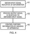
- Fig. 4 is a block diagram which schematically illustrates a method according to examplary embodiments of the disclosure.
- the apparatus 1 illustrated in Figs. 1 and 2 may be used to implement the method of Fig. 4 .
- the input signal may be obtained by a controller 4.
- the input signal may be sensor input signal 39 which may be obtained from one or more sensors 19.
- the one or more sensors 19 may be configured to detect the deformation of the housing 25 of the apparatus 1 and provide a sensor input signal 39 to the controller 4 as described above in relation to Figs. 1 to 3 .
- the sensor input signal 39 which is obtained may provide an indication of the deformation of the housing 25 of the apparatus 1.
- an output signal is provided.
- the output signal may be provided 43 by the controller 4 to the one or more actuators 17.
- the output signal which is provided by the controller 4 may be dependent on the sensor input signal 39 which was obtained by the controller 4 from the one or more sensors 19 at block 41.
- the output signal which is provided at block 43 may also be dependent upon an initial input signal 31 which is also received by the controller 4.
- the initial input signal 31 may be received in response to detecting that an event has occurred and may determine the deformation of the apparatus 1 that is to be provided.
- the actuator 17 controls the further deformation of the housing 25 of the apparatus 1 by moving in accordance with the provided output signal 33.
- the blocks illustrated in the Fig. 4 may represent steps in a method and/or sections of code in the computer program 9.
- the illustration of a particular order to the blocks does not necessarily imply that there is a required or preferred order for the blocks and the order and arrangement of the block may be varied. Furthermore, it may be possible for some blocks to be omitted.
- Figs. 5A and 5B illustrate an apparatus 1 according to an examplary embodiment of the disclosure.
- the apparatus 1 is configured in an un-deformed state.
- the un-deformed state no stress or external force is being applied to the housing 25 of the apparatus 1 by the actuator 17.
- the normal, un-deformed state of the housing of the apparatus 1 comprises a substantially flat rectangular prism.
- the surfaces of the housing 25 are substantially flat.
- the one or more actuators 17 are provided on the surface of the housing 25.
- the actuator 17 may comprise wires 51 comprising a shape memory alloy such as copper-zinc-aluminum-nickel, copper-aluminum-nickel and nickel-titanium.
- the wires may extend across the surface of the housing 25.
- the wires 51 are attached to the surface of the housing 25 so that bending of the wires 51 causes bending of the housing 25 of the apparatus 1. Any suitable means may be used to attach the wires 51 to the surface of the housing 25, for example, the wires 51 may be adhered to the surface of the housing 25 using an adhesive.
- actuator 17 may be used in other embodiments of the disclosure.
- one or more of the actuators 17 may be provided within the housing 25 so that they cannot be viewed when the apparatus 1 is in use.
- Fig. 5B illustrates the apparatus 1 when the housing 25 of the apparatus 1 is deformed.
- the controller 4 has received the initial input signal 31, as described above, and in response to the initial input signal 31 has provided an output signal 33 to the wires 51.
- the output signal 33 has controlled the wires 51 to curve upwards.
- the wires 51 are coupled to the housing 25 the movement of the wires 51 causes the housing 25 to curve upwards with the wires 51.
- the housing 25 of the apparatus 1 illustrated in Fig. 5B is now curved upwards so that the side of the apparatus 1 comprising the wires is concave.
- the apparatus 1 may comprise one or more sensors 19.
- the sensors may be provided within the housing 25 or in any other suitable part of the apparatus 1.
- the sensors 19 may be configured to detect the deformation of the apparatus 1.
- the sensors 19 may be configured to detect the radius of curvature of the housing 25 of the apparatus 1 once it has been deformed and provide feedback to the controller 4. This enables the deformation of the housing 25 to be controlled.
- the deformation illustrated in Figs. 5A and 5B is examplary and that many other deformations could be made to the housing 25 of the apparatus 1.
- the apparatus 1 may be configured to provide a deformation which varies in time.
- a portion of the housing 25 of the apparatus 1 may be configured to move backwards and forward in response to the control signals, such a deformation may be useful in providing an alert to the user of the apparatus 1.
- Embodiments of the disclosure provide an apparatus 1 and method which may be used to control the deformation of a bendable apparatus.
- the one or more sensors 19 provide feedback to the controller about the current deformation of the housing 25 of the apparatus 1 and this can be used to control the further deformation of the housing 25 of the apparatus 1. This may enable the apparatus 1 to be deformed automatically without any direct input by the user of the apparatus 1 because the controller 4 and sensors 19 may be configured to control the deformation.
- the different deformations which are provided may enable the user of the apparatus 1 to easily distinguish between the different events without having to view the apparatus 1.
- the deformation of the apparatus 1 may be used to provide an alert to the user of the apparatus 1.
- the actuator 17 may cause the repeated movement of a portion of the housing of the apparatus 1 which may be detected by the user of the apparatus 1 in a similar manner to a vibration of an apparatus 1.
- the deformation of the apparatus 1 may act to protect components of the apparatus 1.
- the apparatus 1 may comprise a display 15 which may be damaged if the apparatus 1 is dropped.
- the apparatus 1 may comprise accelerometers or other suitable detectors which may be configured to detect when the apparatus 1 has been dropped and provide an initial input signal 31 to the controller 4.
- the initial input signal 16 may cause the actuators 17 to deform the housing 25 of the apparatus 1 by curling the apparatus 1 so that the display 15 is located on a concave side of the housing 25 of the apparatus 1 and the dropped apparatus 1 cannot land on the display 15.
- the one or more sensors 19 may provide feedback to the controller 4 which prevents the deformation of the housing 25 of the apparatus 1 from causing damage to the housing 25 of the apparatus 1.
- the deformation of the housing 25 is caused by stresses and strains being applied to the housing 25 by the actuators 17. If the stresses or strains exceed a threshold then this may cause failure of the housing 25 of the apparatus 1 and cause permanent damage to the housing 25.
- the sensors 19 and controller 4 may be configured to prevent excessive forces being applied to the housing 25 and so protecting the housing 25 from permanent damage.
- the initial input signal 31 is described as comprising information which is indicative of a deformation of the housing of the apparatus 1.
- the initial input signal 31 may comprise information indicative of the event which has been detected.
- the controller 4 may then use this information to determine the deformation of the housing 25 of the apparatus 1. For example, the controller 4 may access a lookup table to determine which deformation should be associated with the detected event.
Landscapes
- Engineering & Computer Science (AREA)
- General Engineering & Computer Science (AREA)
- Theoretical Computer Science (AREA)
- General Physics & Mathematics (AREA)
- Physics & Mathematics (AREA)
- Human Computer Interaction (AREA)
- Computer Hardware Design (AREA)
- Signal Processing (AREA)
- User Interface Of Digital Computer (AREA)
- Telephone Function (AREA)
- Toys (AREA)
- Position Input By Displaying (AREA)
- Electrophonic Musical Instruments (AREA)
Claims (14)
- Appareil comprenant :au moins un processeur ; etau moins une mémoire comprenant un code de programme d'ordinateur ;dans lequel la ou les mémoires et le code de programme d'ordinateur sont configurés, avec le ou les processeurs, pour permettre à l'appareil :d'obtenir, au moyen du processeur, un signal d'entrée indiquant une déformation particulière à apporter à un boîtier de l'appareil à la suite d'une détermination d'une force appliquée à l'appareil dépassant une valeur de seuil ; età la suite du signal d'entrée obtenu, de fournir un signal de sortie pour commander une déformation au boîtier de l'appareil par rapport à la déformation particulière indiquée par le signal d'entrée obtenu et dans lequel le signal de sortie commande une déformation pour empêcher des forces excessives d'être appliquées au boîtier de l'appareil.
- Appareil selon la revendication 1, dans lequel le boîtier comprend un carter externe de l'appareil.
- Appareil selon l'une quelconque des revendications précédentes, dans lequel le boîtier contient le ou les processeurs et la ou les mémoires.
- Appareil selon l'une quelconque des revendications précédentes, dans lequel le signal d'entrée indiquant la déformation particulière à apporter au boîtier de l'appareil est obtenu à partir d'un ou de plusieurs capteurs configurés pour détecter la force appliquée à l'appareil.
- Appareil selon l'une quelconque des revendications précédentes, dans lequel l'appareil comprend un actionneur configuré pour recevoir le signal de sortie en provenance du ou des processeurs et pour commander la déformation du boîtier de l'appareil à la suite du signal de sortie.
- Appareil selon l'une quelconque des revendications précédentes, dans lequel la déformation comprend : le pliage d'au moins une partie du boîtier de l'appareil et/ou l'allongement d'au moins une partie du boîtier de l'appareil et/ou la modification de la forme d'au moins une partie du boîtier de l'appareil.
- Dispositif portatif comprenant l'appareil selon l'une quelconque des revendications précédentes.
- Procédé comprenant :l'obtention, par un processeur, d'un signal d'entrée indiquant une déformation particulière à apporter à un boîtier d'un appareil à la suite d'une détermination d'une force appliquée à l'appareil dépassant une valeur de seuil ; età la suite du signal d'entrée obtenu, la fourniture d'un signal de sortie pour commander une déformation au boîtier de l'appareil par rapport à la déformation particulière indiquée par le signal d'entrée obtenu et dans lequel le signal de sortie commande une déformation pour empêcher des forces excessives d'être appliquées au boîtier de l'appareil.
- Procédé selon la revendication 8, dans lequel le boîtier comprend un carter externe de l'appareil.
- Procédé selon l'une quelconque des revendications 8 et 9, dans lequel le boîtier contient au moins un processeur et au moins une mémoire configurés pour permettre la mise en oeuvre du procédé.
- Procédé selon l'une quelconque des revendications 8 à 10, dans lequel le signal d'entrée indiquant la déformation particulière à apporter au boîtier de l'appareil est obtenue à partir d'un ou de plusieurs capteurs configurés pour détecter la force appliquée à l'appareil.
- Procédé selon l'une quelconque des revendications 8 à 11, dans lequel le signal de sortie pour commander la déformation du boîtier de l'appareil est fourni à un actionneur configuré pour commander la déformation du boîtier de l'appareil à la suite du signal de sortie.
- Procédé selon l'une quelconque des revendications 8 à 12, dans lequel la déformation comprend : le pliage d'au moins une partie du boîtier de l'appareil et/ou l'allongement d'au moins une partie du boîtier de l'appareil et/ou la modification de la forme d'au moins une partie du boîtier de l'appareil.
- Programme d'ordinateur comprenant des instructions de programme d'ordinateur qui, lorsqu'elles sont exécutées par au moins un processeur, permettent à un appareil de réaliser au moins :l'obtention, par le processeur, d'un signal d'entrée indiquant une déformation particulière à apporter à un boîtier de l'appareil à la suite d'une détermination d'une force appliquée à l'appareil dépassant une valeur de seuil ; età la suite du signal d'entrée obtenu, la fourniture d'un signal de sortie pour commander une déformation au boîtier de l'appareil par rapport à la déformation particulière indiquée par le signal d'entrée obtenu et dans lequel le signal de sortie commande une déformation pour empêcher des forces excessives d'être appliquées au boîtier de l'appareil.
Applications Claiming Priority (2)
| Application Number | Priority Date | Filing Date | Title |
|---|---|---|---|
| US13/362,121 US9614981B2 (en) | 2012-01-31 | 2012-01-31 | Deformable apparatus, method and computer program |
| PCT/IB2013/050758 WO2013114277A2 (fr) | 2012-01-31 | 2013-01-29 | Appareil déformable, méthode et programme informatique |
Publications (3)
| Publication Number | Publication Date |
|---|---|
| EP2810140A2 EP2810140A2 (fr) | 2014-12-10 |
| EP2810140A4 EP2810140A4 (fr) | 2015-07-22 |
| EP2810140B1 true EP2810140B1 (fr) | 2018-12-26 |
Family
ID=48870984
Family Applications (1)
| Application Number | Title | Priority Date | Filing Date |
|---|---|---|---|
| EP13743853.7A Not-in-force EP2810140B1 (fr) | 2012-01-31 | 2013-01-29 | Appareil déformable, méthode et programme informatique |
Country Status (4)
| Country | Link |
|---|---|
| US (1) | US9614981B2 (fr) |
| EP (1) | EP2810140B1 (fr) |
| CN (1) | CN104094186B (fr) |
| WO (1) | WO2013114277A2 (fr) |
Families Citing this family (12)
| Publication number | Priority date | Publication date | Assignee | Title |
|---|---|---|---|---|
| CN107741823B (zh) | 2010-05-21 | 2021-11-26 | 诺基亚技术有限公司 | 用于控制设备的显示器输出的方法、设备和计算机程序 |
| US9823707B2 (en) | 2012-01-25 | 2017-11-21 | Nokia Technologies Oy | Contortion of an electronic apparatus |
| US9823696B2 (en) | 2012-04-27 | 2017-11-21 | Nokia Technologies Oy | Limiting movement |
| KR101919848B1 (ko) * | 2012-08-23 | 2018-11-19 | 삼성전자주식회사 | 플렉서블 장치 및 플렉서블 장치의 제어 방법 |
| US9158334B2 (en) * | 2012-10-22 | 2015-10-13 | Nokia Technologies Oy | Electronic device controlled by flexing |
| US9524030B2 (en) * | 2013-04-26 | 2016-12-20 | Immersion Corporation | Haptic feedback for interactions with foldable-bendable displays |
| IN2014CH00115A (fr) * | 2014-01-09 | 2015-07-10 | Samsung R & D Inst India Bangalore Private Ltd | |
| KR20160138137A (ko) | 2014-03-21 | 2016-12-02 | 임머숀 코퍼레이션 | 햅틱적으로 인에이블되는 곡면형 디바이스들을 위한 시스템 및 방법 |
| US9606625B2 (en) * | 2014-10-13 | 2017-03-28 | Immersion Corporation | Haptically-enabled deformable device with rigid component |
| US9432969B1 (en) * | 2015-06-27 | 2016-08-30 | Intel IP Corporation | Shape changing device housing |
| CN106357842A (zh) * | 2015-07-17 | 2017-01-25 | 中兴通讯股份有限公司 | 一种移动终端上输出告警信息的方法和移动终端 |
| CN105094623B (zh) * | 2015-09-14 | 2019-03-29 | 联想(北京)有限公司 | 一种信息处理方法及电子设备 |
Family Cites Families (11)
| Publication number | Priority date | Publication date | Assignee | Title |
|---|---|---|---|---|
| WO2001091100A1 (fr) * | 2000-05-24 | 2001-11-29 | Immersion Corporation | Dispositifs haptiques utilisant des polymeres electroactifs |
| JP3867664B2 (ja) | 2002-12-12 | 2007-01-10 | ソニー株式会社 | 入力装置、携帯型情報処理装置、リモートコントロール装置、および入力装置における圧電アクチュエータ駆動制御方法 |
| JP2006333124A (ja) | 2005-05-26 | 2006-12-07 | Matsushita Electric Ind Co Ltd | 無線通信端末、無線通信端末の情報受信報知方法、及び情報受信報知器 |
| EP2082351A2 (fr) | 2006-11-17 | 2009-07-29 | Mark A. Salada | Dispositif d'interface haptique, et son procédé d'utilisation |
| KR100968905B1 (ko) | 2008-06-03 | 2010-07-14 | 한국과학기술원 | 굽힘을 이용한 햅틱피드백 장치 |
| US9600070B2 (en) | 2008-12-22 | 2017-03-21 | Apple Inc. | User interface having changeable topography |
| US8803798B2 (en) * | 2009-05-07 | 2014-08-12 | Immersion Corporation | System and method for shape deformation and force display of devices |
| US8487759B2 (en) | 2009-09-30 | 2013-07-16 | Apple Inc. | Self adapting haptic device |
| EP2315186B1 (fr) * | 2009-10-26 | 2016-09-21 | Lg Electronics Inc. | Terminal mobile avec un boîtier flexible pour entrer un signal lors de la flexion dudit boîtier |
| US20110216013A1 (en) | 2010-03-05 | 2011-09-08 | Sony Ericsson Mobile Communications Ab | Touch-sensitive input device, touch screen device, mobile device and method for operating a touch-sensitive input device |
| US20110267181A1 (en) | 2010-04-29 | 2011-11-03 | Nokia Corporation | Apparatus and method for providing tactile feedback for user |
-
2012
- 2012-01-31 US US13/362,121 patent/US9614981B2/en not_active Expired - Fee Related
-
2013
- 2013-01-29 CN CN201380007140.5A patent/CN104094186B/zh not_active Expired - Fee Related
- 2013-01-29 WO PCT/IB2013/050758 patent/WO2013114277A2/fr not_active Ceased
- 2013-01-29 EP EP13743853.7A patent/EP2810140B1/fr not_active Not-in-force
Also Published As
| Publication number | Publication date |
|---|---|
| WO2013114277A2 (fr) | 2013-08-08 |
| EP2810140A4 (fr) | 2015-07-22 |
| WO2013114277A3 (fr) | 2013-12-27 |
| EP2810140A2 (fr) | 2014-12-10 |
| CN104094186A (zh) | 2014-10-08 |
| US9614981B2 (en) | 2017-04-04 |
| US20130197819A1 (en) | 2013-08-01 |
| CN104094186B (zh) | 2018-04-13 |
Similar Documents
| Publication | Publication Date | Title |
|---|---|---|
| EP2810140B1 (fr) | Appareil déformable, méthode et programme informatique | |
| EP2791759B1 (fr) | Boîtier | |
| US10416774B2 (en) | Automatic remote sensing and haptic conversion system | |
| US10394285B2 (en) | Systems and methods for deformation and haptic effects | |
| EP3373383B1 (fr) | Procédé permettant de détecter le gonflement d'une batterie au moyen d'un capteur de pression et dispositif électronique utilisant le procédé | |
| CN105765338B (zh) | 柔性设备形变测量 | |
| EP2846219A1 (fr) | Système de conversion haptique utilisant un décalage de fréquence | |
| CA2712733C (fr) | Dispositif electronique portatif comprenant un ecran tactile, et methode de commande | |
| US20110084932A1 (en) | Portable electronic device including touch-sensitive display and method of controlling same | |
| WO2013068791A1 (fr) | Procédé d'interface utilisateur et appareil permettant de fournir une entrée sensible à la déformation | |
| US20170031495A1 (en) | Noise Adaptive Force Touch | |
| EP2817702B1 (fr) | Procédé, appareil et programme pour afficher un contenu sur un ecran pliable | |
| EP2390766B1 (fr) | Dispositif électronique incluant un affichage sensible au toucher et son procédé de contrôle | |
| EP2357547A1 (fr) | Dispositif électronique portable et son procédé de contrôle | |
| US10132706B2 (en) | Waterproof barometric sensor in an electronic device | |
| EP2572260B1 (fr) | Procédé, appareil et programme informatique destinés à commander la sortie d'un afficheur d'un appareil | |
| KR102933772B1 (ko) | 전자 장치 및 그의 상황을 감지하는 방법 | |
| EP2320308A1 (fr) | Dispositif électronique portable incluant un écran tactile et son procédé de commande | |
| US9383847B2 (en) | Portable electronic device including touch-sensitive display and method of controlling same | |
| CN112462966B (zh) | 3d触摸 | |
| JP6778656B2 (ja) | 電子機器、感度補正方法及び感度補正プログラム | |
| US9223343B2 (en) | Apparatus, method and computer program | |
| JP6223383B2 (ja) | 携帯装置、制御方法、及び制御プログラム | |
| CN107632545A (zh) | 数据传输控制方法及相关产品 |
Legal Events
| Date | Code | Title | Description |
|---|---|---|---|
| PUAI | Public reference made under article 153(3) epc to a published international application that has entered the european phase |
Free format text: ORIGINAL CODE: 0009012 |
|
| 17P | Request for examination filed |
Effective date: 20140626 |
|
| AK | Designated contracting states |
Kind code of ref document: A2 Designated state(s): AL AT BE BG CH CY CZ DE DK EE ES FI FR GB GR HR HU IE IS IT LI LT LU LV MC MK MT NL NO PL PT RO RS SE SI SK SM TR |
|
| AX | Request for extension of the european patent |
Extension state: BA ME |
|
| DAX | Request for extension of the european patent (deleted) | ||
| A4 | Supplementary search report drawn up and despatched |
Effective date: 20150622 |
|
| RIC1 | Information provided on ipc code assigned before grant |
Ipc: H04M 19/04 20060101ALI20150616BHEP Ipc: G06F 3/01 20060101ALI20150616BHEP Ipc: H04M 1/02 20060101ALI20150616BHEP Ipc: G06F 1/16 20060101AFI20150616BHEP |
|
| RAP1 | Party data changed (applicant data changed or rights of an application transferred) |
Owner name: NOKIA TECHNOLOGIES OY |
|
| STAA | Information on the status of an ep patent application or granted ep patent |
Free format text: STATUS: EXAMINATION IS IN PROGRESS |
|
| 17Q | First examination report despatched |
Effective date: 20170331 |
|
| GRAP | Despatch of communication of intention to grant a patent |
Free format text: ORIGINAL CODE: EPIDOSNIGR1 |
|
| STAA | Information on the status of an ep patent application or granted ep patent |
Free format text: STATUS: GRANT OF PATENT IS INTENDED |
|
| INTG | Intention to grant announced |
Effective date: 20180629 |
|
| GRAJ | Information related to disapproval of communication of intention to grant by the applicant or resumption of examination proceedings by the epo deleted |
Free format text: ORIGINAL CODE: EPIDOSDIGR1 |
|
| STAA | Information on the status of an ep patent application or granted ep patent |
Free format text: STATUS: EXAMINATION IS IN PROGRESS |
|
| GRAR | Information related to intention to grant a patent recorded |
Free format text: ORIGINAL CODE: EPIDOSNIGR71 |
|
| GRAS | Grant fee paid |
Free format text: ORIGINAL CODE: EPIDOSNIGR3 |
|
| STAA | Information on the status of an ep patent application or granted ep patent |
Free format text: STATUS: GRANT OF PATENT IS INTENDED |
|
| GRAA | (expected) grant |
Free format text: ORIGINAL CODE: 0009210 |
|
| STAA | Information on the status of an ep patent application or granted ep patent |
Free format text: STATUS: THE PATENT HAS BEEN GRANTED |
|
| INTC | Intention to grant announced (deleted) | ||
| AK | Designated contracting states |
Kind code of ref document: B1 Designated state(s): AL AT BE BG CH CY CZ DE DK EE ES FI FR GB GR HR HU IE IS IT LI LT LU LV MC MK MT NL NO PL PT RO RS SE SI SK SM TR |
|
| INTG | Intention to grant announced |
Effective date: 20181120 |
|
| REG | Reference to a national code |
Ref country code: GB Ref legal event code: FG4D |
|
| REG | Reference to a national code |
Ref country code: CH Ref legal event code: EP |
|
| REG | Reference to a national code |
Ref country code: AT Ref legal event code: REF Ref document number: 1082282 Country of ref document: AT Kind code of ref document: T Effective date: 20190115 |
|
| REG | Reference to a national code |
Ref country code: DE Ref legal event code: R096 Ref document number: 602013048797 Country of ref document: DE |
|
| REG | Reference to a national code |
Ref country code: IE Ref legal event code: FG4D |
|
| PG25 | Lapsed in a contracting state [announced via postgrant information from national office to epo] |
Ref country code: HR Free format text: LAPSE BECAUSE OF FAILURE TO SUBMIT A TRANSLATION OF THE DESCRIPTION OR TO PAY THE FEE WITHIN THE PRESCRIBED TIME-LIMIT Effective date: 20181226 Ref country code: LV Free format text: LAPSE BECAUSE OF FAILURE TO SUBMIT A TRANSLATION OF THE DESCRIPTION OR TO PAY THE FEE WITHIN THE PRESCRIBED TIME-LIMIT Effective date: 20181226 Ref country code: FI Free format text: LAPSE BECAUSE OF FAILURE TO SUBMIT A TRANSLATION OF THE DESCRIPTION OR TO PAY THE FEE WITHIN THE PRESCRIBED TIME-LIMIT Effective date: 20181226 Ref country code: NO Free format text: LAPSE BECAUSE OF FAILURE TO SUBMIT A TRANSLATION OF THE DESCRIPTION OR TO PAY THE FEE WITHIN THE PRESCRIBED TIME-LIMIT Effective date: 20190326 Ref country code: LT Free format text: LAPSE BECAUSE OF FAILURE TO SUBMIT A TRANSLATION OF THE DESCRIPTION OR TO PAY THE FEE WITHIN THE PRESCRIBED TIME-LIMIT Effective date: 20181226 Ref country code: BG Free format text: LAPSE BECAUSE OF FAILURE TO SUBMIT A TRANSLATION OF THE DESCRIPTION OR TO PAY THE FEE WITHIN THE PRESCRIBED TIME-LIMIT Effective date: 20190326 |
|
| REG | Reference to a national code |
Ref country code: NL Ref legal event code: MP Effective date: 20181226 |
|
| REG | Reference to a national code |
Ref country code: LT Ref legal event code: MG4D |
|
| PG25 | Lapsed in a contracting state [announced via postgrant information from national office to epo] |
Ref country code: AL Free format text: LAPSE BECAUSE OF FAILURE TO SUBMIT A TRANSLATION OF THE DESCRIPTION OR TO PAY THE FEE WITHIN THE PRESCRIBED TIME-LIMIT Effective date: 20181226 Ref country code: SE Free format text: LAPSE BECAUSE OF FAILURE TO SUBMIT A TRANSLATION OF THE DESCRIPTION OR TO PAY THE FEE WITHIN THE PRESCRIBED TIME-LIMIT Effective date: 20181226 Ref country code: RS Free format text: LAPSE BECAUSE OF FAILURE TO SUBMIT A TRANSLATION OF THE DESCRIPTION OR TO PAY THE FEE WITHIN THE PRESCRIBED TIME-LIMIT Effective date: 20181226 Ref country code: GR Free format text: LAPSE BECAUSE OF FAILURE TO SUBMIT A TRANSLATION OF THE DESCRIPTION OR TO PAY THE FEE WITHIN THE PRESCRIBED TIME-LIMIT Effective date: 20190327 |
|
| REG | Reference to a national code |
Ref country code: AT Ref legal event code: MK05 Ref document number: 1082282 Country of ref document: AT Kind code of ref document: T Effective date: 20181226 |
|
| PG25 | Lapsed in a contracting state [announced via postgrant information from national office to epo] |
Ref country code: NL Free format text: LAPSE BECAUSE OF FAILURE TO SUBMIT A TRANSLATION OF THE DESCRIPTION OR TO PAY THE FEE WITHIN THE PRESCRIBED TIME-LIMIT Effective date: 20181226 |
|
| PG25 | Lapsed in a contracting state [announced via postgrant information from national office to epo] |
Ref country code: PL Free format text: LAPSE BECAUSE OF FAILURE TO SUBMIT A TRANSLATION OF THE DESCRIPTION OR TO PAY THE FEE WITHIN THE PRESCRIBED TIME-LIMIT Effective date: 20181226 Ref country code: CZ Free format text: LAPSE BECAUSE OF FAILURE TO SUBMIT A TRANSLATION OF THE DESCRIPTION OR TO PAY THE FEE WITHIN THE PRESCRIBED TIME-LIMIT Effective date: 20181226 Ref country code: PT Free format text: LAPSE BECAUSE OF FAILURE TO SUBMIT A TRANSLATION OF THE DESCRIPTION OR TO PAY THE FEE WITHIN THE PRESCRIBED TIME-LIMIT Effective date: 20190426 Ref country code: ES Free format text: LAPSE BECAUSE OF FAILURE TO SUBMIT A TRANSLATION OF THE DESCRIPTION OR TO PAY THE FEE WITHIN THE PRESCRIBED TIME-LIMIT Effective date: 20181226 Ref country code: IT Free format text: LAPSE BECAUSE OF FAILURE TO SUBMIT A TRANSLATION OF THE DESCRIPTION OR TO PAY THE FEE WITHIN THE PRESCRIBED TIME-LIMIT Effective date: 20181226 |
|
| PG25 | Lapsed in a contracting state [announced via postgrant information from national office to epo] |
Ref country code: EE Free format text: LAPSE BECAUSE OF FAILURE TO SUBMIT A TRANSLATION OF THE DESCRIPTION OR TO PAY THE FEE WITHIN THE PRESCRIBED TIME-LIMIT Effective date: 20181226 Ref country code: SM Free format text: LAPSE BECAUSE OF FAILURE TO SUBMIT A TRANSLATION OF THE DESCRIPTION OR TO PAY THE FEE WITHIN THE PRESCRIBED TIME-LIMIT Effective date: 20181226 Ref country code: RO Free format text: LAPSE BECAUSE OF FAILURE TO SUBMIT A TRANSLATION OF THE DESCRIPTION OR TO PAY THE FEE WITHIN THE PRESCRIBED TIME-LIMIT Effective date: 20181226 Ref country code: SK Free format text: LAPSE BECAUSE OF FAILURE TO SUBMIT A TRANSLATION OF THE DESCRIPTION OR TO PAY THE FEE WITHIN THE PRESCRIBED TIME-LIMIT Effective date: 20181226 Ref country code: IS Free format text: LAPSE BECAUSE OF FAILURE TO SUBMIT A TRANSLATION OF THE DESCRIPTION OR TO PAY THE FEE WITHIN THE PRESCRIBED TIME-LIMIT Effective date: 20190426 |
|
| REG | Reference to a national code |
Ref country code: CH Ref legal event code: PL |
|
| RAP2 | Party data changed (patent owner data changed or rights of a patent transferred) |
Owner name: NOKIA TECHNOLOGIES OY |
|
| REG | Reference to a national code |
Ref country code: DE Ref legal event code: R097 Ref document number: 602013048797 Country of ref document: DE |
|
| PG25 | Lapsed in a contracting state [announced via postgrant information from national office to epo] |
Ref country code: LU Free format text: LAPSE BECAUSE OF NON-PAYMENT OF DUE FEES Effective date: 20190129 |
|
| REG | Reference to a national code |
Ref country code: BE Ref legal event code: MM Effective date: 20190131 |
|
| REG | Reference to a national code |
Ref country code: IE Ref legal event code: MM4A |
|
| PG25 | Lapsed in a contracting state [announced via postgrant information from national office to epo] |
Ref country code: MC Free format text: LAPSE BECAUSE OF FAILURE TO SUBMIT A TRANSLATION OF THE DESCRIPTION OR TO PAY THE FEE WITHIN THE PRESCRIBED TIME-LIMIT Effective date: 20181226 Ref country code: AT Free format text: LAPSE BECAUSE OF FAILURE TO SUBMIT A TRANSLATION OF THE DESCRIPTION OR TO PAY THE FEE WITHIN THE PRESCRIBED TIME-LIMIT Effective date: 20181226 Ref country code: DK Free format text: LAPSE BECAUSE OF FAILURE TO SUBMIT A TRANSLATION OF THE DESCRIPTION OR TO PAY THE FEE WITHIN THE PRESCRIBED TIME-LIMIT Effective date: 20181226 |
|
| PLBE | No opposition filed within time limit |
Free format text: ORIGINAL CODE: 0009261 |
|
| STAA | Information on the status of an ep patent application or granted ep patent |
Free format text: STATUS: NO OPPOSITION FILED WITHIN TIME LIMIT |
|
| GBPC | Gb: european patent ceased through non-payment of renewal fee |
Effective date: 20190326 |
|
| PG25 | Lapsed in a contracting state [announced via postgrant information from national office to epo] |
Ref country code: BE Free format text: LAPSE BECAUSE OF NON-PAYMENT OF DUE FEES Effective date: 20190131 |
|
| 26N | No opposition filed |
Effective date: 20190927 |
|
| PG25 | Lapsed in a contracting state [announced via postgrant information from national office to epo] |
Ref country code: CH Free format text: LAPSE BECAUSE OF NON-PAYMENT OF DUE FEES Effective date: 20190131 Ref country code: LI Free format text: LAPSE BECAUSE OF NON-PAYMENT OF DUE FEES Effective date: 20190131 |
|
| PG25 | Lapsed in a contracting state [announced via postgrant information from national office to epo] |
Ref country code: IE Free format text: LAPSE BECAUSE OF NON-PAYMENT OF DUE FEES Effective date: 20190129 Ref country code: GB Free format text: LAPSE BECAUSE OF NON-PAYMENT OF DUE FEES Effective date: 20190326 |
|
| PG25 | Lapsed in a contracting state [announced via postgrant information from national office to epo] |
Ref country code: FR Free format text: LAPSE BECAUSE OF NON-PAYMENT OF DUE FEES Effective date: 20190226 Ref country code: SI Free format text: LAPSE BECAUSE OF FAILURE TO SUBMIT A TRANSLATION OF THE DESCRIPTION OR TO PAY THE FEE WITHIN THE PRESCRIBED TIME-LIMIT Effective date: 20181226 |
|
| PG25 | Lapsed in a contracting state [announced via postgrant information from national office to epo] |
Ref country code: TR Free format text: LAPSE BECAUSE OF FAILURE TO SUBMIT A TRANSLATION OF THE DESCRIPTION OR TO PAY THE FEE WITHIN THE PRESCRIBED TIME-LIMIT Effective date: 20181226 |
|
| PGFP | Annual fee paid to national office [announced via postgrant information from national office to epo] |
Ref country code: DE Payment date: 20200114 Year of fee payment: 8 |
|
| PG25 | Lapsed in a contracting state [announced via postgrant information from national office to epo] |
Ref country code: MT Free format text: LAPSE BECAUSE OF NON-PAYMENT OF DUE FEES Effective date: 20190129 |
|
| PG25 | Lapsed in a contracting state [announced via postgrant information from national office to epo] |
Ref country code: CY Free format text: LAPSE BECAUSE OF FAILURE TO SUBMIT A TRANSLATION OF THE DESCRIPTION OR TO PAY THE FEE WITHIN THE PRESCRIBED TIME-LIMIT Effective date: 20181226 |
|
| PG25 | Lapsed in a contracting state [announced via postgrant information from national office to epo] |
Ref country code: HU Free format text: LAPSE BECAUSE OF FAILURE TO SUBMIT A TRANSLATION OF THE DESCRIPTION OR TO PAY THE FEE WITHIN THE PRESCRIBED TIME-LIMIT; INVALID AB INITIO Effective date: 20130129 |
|
| REG | Reference to a national code |
Ref country code: DE Ref legal event code: R119 Ref document number: 602013048797 Country of ref document: DE |
|
| PG25 | Lapsed in a contracting state [announced via postgrant information from national office to epo] |
Ref country code: DE Free format text: LAPSE BECAUSE OF NON-PAYMENT OF DUE FEES Effective date: 20210803 |
|
| PG25 | Lapsed in a contracting state [announced via postgrant information from national office to epo] |
Ref country code: MK Free format text: LAPSE BECAUSE OF FAILURE TO SUBMIT A TRANSLATION OF THE DESCRIPTION OR TO PAY THE FEE WITHIN THE PRESCRIBED TIME-LIMIT Effective date: 20181226 |