EP2810285B1 - Récipient sans renforcement pour appareil électromagnétique - Google Patents
Récipient sans renforcement pour appareil électromagnétique Download PDFInfo
- Publication number
- EP2810285B1 EP2810285B1 EP13711850.1A EP13711850A EP2810285B1 EP 2810285 B1 EP2810285 B1 EP 2810285B1 EP 13711850 A EP13711850 A EP 13711850A EP 2810285 B1 EP2810285 B1 EP 2810285B1
- Authority
- EP
- European Patent Office
- Prior art keywords
- tank
- profile
- side wall
- curving
- bottom edge
- Prior art date
- Legal status (The legal status is an assumption and is not a legal conclusion. Google has not performed a legal analysis and makes no representation as to the accuracy of the status listed.)
- Active
Links
Images



Classifications
-
- H—ELECTRICITY
- H01—ELECTRIC ELEMENTS
- H01F—MAGNETS; INDUCTANCES; TRANSFORMERS; SELECTION OF MATERIALS FOR THEIR MAGNETIC PROPERTIES
- H01F27/00—Details of transformers or inductances, in general
- H01F27/02—Casings
- H01F27/025—Constructional details relating to cooling
-
- H—ELECTRICITY
- H01—ELECTRIC ELEMENTS
- H01F—MAGNETS; INDUCTANCES; TRANSFORMERS; SELECTION OF MATERIALS FOR THEIR MAGNETIC PROPERTIES
- H01F27/00—Details of transformers or inductances, in general
- H01F27/02—Casings
Definitions
- This invention is generally related to an electromagnetic apparatus, such as a transformer, as may be immersed in a fluid in a tank, and, more particularly, but not exclusively, to a reinforcement-free tank, as may contain such an electromagnetic apparatus and fluid.
- an electromagnetic apparatus such as a transformer
- a reinforcement-free tank as may contain such an electromagnetic apparatus and fluid.
- Various electromagnetic apparatuses such as transformers, autotransformers, reactors, may be immersed in a fluid (e.g., liquid and/or gaseous fluid) to ensure appropriate electrical isolation and/or cooling. Accordingly, such electrical apparatuses may utilize a tank structure to contain one or more of their active components immersed in the fluid.
- a fluid e.g., liquid and/or gaseous fluid
- Such tanks may commonly involve the use of reinforcement structures (e.g., girders, etc.) as may be welded to walls of the tank for providing appropriate structural integrity so that the walls of the tank can appropriately withstand vacuum and overpressure conditions which can develop in the tank.
- reinforcement structures e.g., girders, etc.
- JP S 57 10911 A shows a tank with increased pressure strength, where a reinforcing ring is fixed at the position of the top surface of a flat plate cover corresponding to an entire circumference of a side wall of the tank.
- DE 554 718 C shows a tank with convex side and end walls which has less space requirements than tanks with circular or elliptic cross section and has a increased pressure resistance than tanks with rectangular cross section.
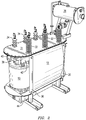
- FIG. 1 is an isometric view of an example electromagnetic apparatus, as may include a reinforcement-free tank 10 embodying aspects of the present invention.
- tank 10 may be used for accommodating one or more active components of the electromagnetic apparatus (e.g., transformer, autotransformer, reactor), which may be immersed in a fluid.
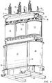
- active components which may be immersed in the fluid may be a core 11 ( FIG. 4 ) and one or more windings 13, as may be appreciated in FIGs. 2-4 and 9 .
- tank 10 may include a pair of mutually-opposite side walls 12.
- FIG. 1 shows just one of side walls 12.
- Each side wall 12 may include at least one curved segment defining a vertically-curving profile 14 (an example embodiment may be better appreciated in FIG. 4 ) between a top edge 16 and a bottom edge 18 of a side wall 12.
- Tank 10 may further include a pair of mutually-opposite end walls 20.
- FIG. 1 shows just one of end walls 20.
- Each end wall 20 may have a substantially vertically-extending semi-cylindrical shape 22 defining a vertically-straight profile 24 between a top edge 26 and a bottom edge 28 of an end wall 20.
- Tank 10 may further include one or more vertically-extending joining members 30.
- Each joining member 30 may be configured to provide a transition between the vertically-curving profile 14 of a side wall 12 and the vertically-straight profile 24 of a corresponding end wall 20.
- the transition between the vertically-curving profile of a side wall 12 and the vertically-straight profile of a corresponding end wall 20 may be a welded joint.
- side walls 12 and end walls 20 can withstand vacuum and overpressure conditions which can develop in the tank without a reinforcing member connected to the walls.
- tank 10 includes a top 31 for covering a top opening of the tank.
- FIG. 1 further illustrates example high-voltage bushings 32 and example low-voltage bushings 34, as may be used in a typical power transformer application. It will be appreciated that aspects of the present invention are not limited to the number and/or position of the example bushings illustrated in the figures.
- a standard conservator tank 36 may be used for allowing expansion and contraction of fluid in the tank, such as may occur due to temperature changes during operation of the transformer.
- a support structure 38 which in one example embodiment may comprise a pair of clamping members 40, 42, may provide a surface 45, which may be continually joined (e.g., by way of a load-carrying welded joint) along its length to a corresponding underside of top 31.
- Support structure 38 e.g., by way of clamping members 40, 42
- top 31 can withstand the vacuum and overpressure conditions which can develop in the tank without a further reinforcing member connected to the top.
- a base 44 may be arranged to support one or more corresponding lower sections of the active components, such as core 11 and/or winding 13.
- base 44 may comprise a substantially "U" shaped cross-section and may be arranged to cover a bottom opening of the tank.
- FIGs. 5-8 show respective example embodiments of vertically-curving profiles of side walls 12, as may be used in a reinforcement-free tank embodying aspects of the present invention.
- vertically-curving profile 14 may be a concave profile 50, such as curving outwardly toward its center between the top edge and the bottom edge of the side wall.
- vertically-curving profile 14 may comprise a flaring profile 52, such as may expand outwardly between the bottom edge and the top edge of the side wall, or, alternatively, may contract inwardly between the bottom edge and the top edge of the side wall (for example, visualize flaring profile 52 being turned upside down).
- vertically-curving profile 14 may be a serpentine profile 54, such as may include two or more curved segments.
- vertically-curving profile 14 may be a convex profile 56 curving inwardly toward its center between the top edge and the bottom edge of the side wall.
- Example applications of a tank embodying aspects of the invention may be transformers involving any of various cooling methodologies, such as “Oil Natural Air Natural” (ONAN), “Oil Natural Air Forced” (ONAF), “Oil Forced Air Forced” (OFAF), “Oil Forced Water Forced” OFWF transformers, any liquid-immersed transformer, transformers in mobile substations, etc.
Landscapes
- Engineering & Computer Science (AREA)
- Power Engineering (AREA)
- Housings And Mounting Of Transformers (AREA)
- Filling Or Discharging Of Gas Storage Vessels (AREA)
Claims (16)
- Récipient (10) sans renfort pour un appareil électromagnétique immergé dans un fluide, le récipient comprenant :une paire de parois (12) latérales opposées mutuellement, chaque paroi (12) latérale comprenant au moins un segment incurvé définissant un profil (14) s'incurvant verticalement entre un bord (16) de sommet et un bord (18) de fond d'une paroi (12) latérale,une paire de parois (20) d'extrémité opposées mutuellement, chaque paroi (20) d'extrémité comprenant une forme hémicylindrique s'étendant sensiblement verticalement et définissant un profil droit verticalement entre un bord (26) de sommet et un bord (28) de fond d'une paroi (20) d'extrémité ; etdes éléments (30) de jonction s'étendant verticalement, chaque élément (30) de jonction étant configuré pour donner une transition entre le profil (14) s'incurvant verticalement d'une paroi (12) latérale, et le profil (24) droit verticalement d'une paroi (20) d'extrémité correspondante, les parois (12, 20) pouvant résister à des conditions de vide et/ou de surpression qui peuvent apparaître dans le récipient (10) sans un élément de renfort relié aux parois (12, 20).
- Réservoir (10) suivant la revendication 1, comprenant en outre un sommet (31) pour recouvrir une ouverture de sommet du réservoir.
- Réservoir (10) suivant la revendication 2, comprenant en outre une structure (38) de support comprenant une surface jointe continuellement sur sa longueur à une face inférieure du sommet (31), la structure (38) de support étant agencée en outre pour supporter au moins un élément de l'appareil électromagnétique disposé dans le réservoir (10), le sommet (31) pouvant résister à des conditions de vide et/ou de surpression qui peuvent apparaître dans le réservoir (10) sans un autre élément de renfort relié au sommet (31).
- Réservoir (10) suivant la revendication 2, comprenant en outre un socle (44) de section transversale sensiblement en forme de U, le socle (44) étant agencé pour recouvrir une ouverture de fond du réservoir (10).
- Réservoir (10) suivant la revendication 1, dans lequel le profil (14) s'incurvant verticalement comprend un profil (50) concave s'incurvant vers l'extérieur en direction de son centre entre le bord (16) de sommet et le bord (18) de fond de la paroi (12) latérale.
- Réservoir (10) suivant la revendication 1, dans lequel le profil (14) s'incurvant verticalement comprend un profil (56) convexe s'incurvant vers l'intérieur en direction de son centre, entre le bord (16) de sommet et le bord (18) de fond de la paroi (12) latérale.
- Réservoir (10) suivant la revendication 1, dans lequel le profil (14) s'incurvant verticalement comprend un profil (52) s'évasant entre le bord (16) de sommet et le bord (18) de fond de la paroi (12) latérale.
- Réservoir (10) suivant la revendication 1, dans lequel le profil (14) s'incurvant verticalement comprend un profil (54) sinueux comprenant au moins deux segments incurvés entre le bord (16) de sommet et le bord (18) de fond de la paroi (12) latérale.
- Réservoir (10) suivant la revendication 1, dans lequel le au moins un élément de l'appareil électromagnétique disposé dans le réservoir (10) comprend un noyau (11) et au moins un enroulement (13).
- Réservoir (10) suivant la revendication 1, dans lequel la transition entre le profil (14) s'incurvant verticalement d'une paroi (12) latérale et de profil (24) droit verticalement d'une paroi (20) d'extrémité correspondante comprend un joint soudé.
- Réservoir (10) suivant la revendication 3, dans lequel la structure (38) de support est jointe continuellement sur la longueur à la face inférieure du sommet (31), à l'aide d'un joint soudé supportant une charge.
- Réservoir (10) suivant la revendication 1, dans lequel l'appareil électromagnétique comprend un appareil choisi dans le groupe consistant en un transformateur, un autotransformateur et un réacteur.
- Transformateur comprenant le récipient (10) de la revendication 1.
- Appareil électromagnétique comprenant :le réservoir (10) sans renfort de la revendication 3 pour loger un noyau d'un transformateur et au moins un enroulement du transformateur immergé dans un fluide.
- Appareil électromagnétique suivant la revendication 14, dans lequel le profil (14) s'incurvant verticalement comprend un profil choisi dans le groupe consistant en un profil (50) concave s'incurvant vers l'extérieur en direction de son centre entre le bord (16) de sommet et le bord (18) de fond de la paroi (12) latérale, un profil (56) convexe s'incurvant vers l'intérieur en direction de son centre entre le bord (16) de sommet et le bord (18) de fond de la paroi (12) latérale, un profil (52) s'évasant entre le bord (16) de sommet et le bord (18) de fond de la paroi (12) latérale, et un profil (54) sinueux comprenant au moins deux segments incurvés entre le bord (16) de sommet et le bord (18) de fond de la paroi (12) latérale.
- Appareil électromagnétique suivant la revendication 14, dans lequel la structure (38) de support est jointe continuellement sur sa longueur à la face inférieure du sommet (31) à l'aide d'un joint soudé supportant une charge.
Applications Claiming Priority (2)
| Application Number | Priority Date | Filing Date | Title |
|---|---|---|---|
| US201261610215P | 2012-03-13 | 2012-03-13 | |
| PCT/EP2013/054823 WO2013135603A1 (fr) | 2012-03-13 | 2013-03-11 | Récipient sans renforcement pour appareil électromagnétique |
Publications (2)
| Publication Number | Publication Date |
|---|---|
| EP2810285A1 EP2810285A1 (fr) | 2014-12-10 |
| EP2810285B1 true EP2810285B1 (fr) | 2016-05-04 |
Family
ID=47997378
Family Applications (1)
| Application Number | Title | Priority Date | Filing Date |
|---|---|---|---|
| EP13711850.1A Active EP2810285B1 (fr) | 2012-03-13 | 2013-03-11 | Récipient sans renforcement pour appareil électromagnétique |
Country Status (7)
| Country | Link |
|---|---|
| US (1) | US9437359B2 (fr) |
| EP (1) | EP2810285B1 (fr) |
| BR (1) | BR112014022604B8 (fr) |
| HU (1) | HUE030023T2 (fr) |
| MX (1) | MX2014010869A (fr) |
| PL (1) | PL2810285T3 (fr) |
| WO (1) | WO2013135603A1 (fr) |
Families Citing this family (5)
| Publication number | Priority date | Publication date | Assignee | Title |
|---|---|---|---|---|
| JP6200710B2 (ja) * | 2013-07-12 | 2017-09-20 | 株式会社日立産機システム | 変圧器 |
| WO2019064230A1 (fr) * | 2017-09-27 | 2019-04-04 | Efacec Energia - Máquinas E Equipamentos Eléctricos, S.A. | Réservoir pour transformateur et transformateur associé |
| EP3764377A1 (fr) * | 2019-07-09 | 2021-01-13 | ABB Schweiz AG | Cuve du transformateur ou reacteur a enveloppe remplie de liquide |
| CN112489965B (zh) * | 2020-11-19 | 2021-09-21 | 浙江江山博奥电气有限公司 | 一种降噪音绝缘变压器 |
| JP7433259B2 (ja) * | 2021-02-03 | 2024-02-19 | 株式会社日立産機システム | 変圧器 |
Family Cites Families (8)
| Publication number | Priority date | Publication date | Assignee | Title |
|---|---|---|---|---|
| US1526347A (en) * | 1920-01-08 | 1925-02-17 | Westinghouse Electric & Mfg Co | Transformer tank |
| DE554718C (de) * | 1928-05-19 | 1932-07-12 | Siemens Schuckertwerke Akt Ges | Behaelter mit gewoelbten Seitenwaenden fuer in OEl arbeitende elektrische Apparate, wie Transformatoren |
| GB2050069B (en) * | 1979-05-02 | 1983-05-18 | Tokyo Shibaura Electric Co | Tanks for use in liquid filled electric apparatus |
| JPS5710911A (en) * | 1980-06-24 | 1982-01-20 | Toshiba Corp | Tank for oil-immersed electric equipment |
| JPS5853810A (ja) * | 1981-09-26 | 1983-03-30 | Toshiba Corp | 変圧器 |
| JPS61135104A (ja) * | 1984-12-06 | 1986-06-23 | Toshiba Corp | 変圧器タンク |
| MXNL05000025A (es) * | 2005-03-11 | 2006-09-11 | Prolec Ge S De R L De C V | Tanque para aparato electrico inmerso en fluido. |
| US8717134B2 (en) * | 2008-09-17 | 2014-05-06 | General Electric Company | System with directional pressure venting |
-
2013
- 2013-03-11 HU HUE13711850A patent/HUE030023T2/en unknown
- 2013-03-11 US US14/385,223 patent/US9437359B2/en active Active
- 2013-03-11 PL PL13711850T patent/PL2810285T3/pl unknown
- 2013-03-11 BR BR112014022604A patent/BR112014022604B8/pt active IP Right Grant
- 2013-03-11 EP EP13711850.1A patent/EP2810285B1/fr active Active
- 2013-03-11 WO PCT/EP2013/054823 patent/WO2013135603A1/fr not_active Ceased
- 2013-03-11 MX MX2014010869A patent/MX2014010869A/es active IP Right Grant
Also Published As
| Publication number | Publication date |
|---|---|
| US9437359B2 (en) | 2016-09-06 |
| BR112014022604B1 (pt) | 2021-09-08 |
| US20150091682A1 (en) | 2015-04-02 |
| WO2013135603A1 (fr) | 2013-09-19 |
| BR112014022604A2 (pt) | 2021-06-01 |
| PL2810285T3 (pl) | 2017-04-28 |
| BR112014022604B8 (pt) | 2023-04-25 |
| EP2810285A1 (fr) | 2014-12-10 |
| MX2014010869A (es) | 2014-12-10 |
| HUE030023T2 (en) | 2017-04-28 |
Similar Documents
| Publication | Publication Date | Title |
|---|---|---|
| US9437359B2 (en) | Reinforcement-free tank for an electromagnetic apparatus | |
| US10784034B2 (en) | Core structure and magnetic device | |
| US12040117B2 (en) | Tank for transformer and transformer thereof | |
| TWI501267B (zh) | transformer | |
| JP2010045110A (ja) | リアクトル集合体 | |
| MXNL05000025A (es) | Tanque para aparato electrico inmerso en fluido. | |
| EP2187407A1 (fr) | Dispositif de câble de sortie d'une bobine de réacteur et réacteur à noyau de fer le comprenant | |
| US8928446B2 (en) | Transformer | |
| EP2187408A1 (fr) | Réacteur à noyau de fer | |
| WO2014066075A1 (fr) | Transformateur ayant une armature centrale d'inter-verrouillage | |
| WO2018235322A1 (fr) | Transformateur rempli d'huile et procédé de production de réservoir utilisé dans celui-ci | |
| JP2015141914A (ja) | 静止誘導電器 | |
| JP6491835B2 (ja) | 静止誘導電器 | |
| EP2187409A1 (fr) | Structure de réacteur à doubles parties actives | |
| CN101192465B (zh) | 非晶合金单相油浸式配电变压器 | |
| KR20250138461A (ko) | 변압기 | |
| JP2016039245A (ja) | 変圧器及び変圧器用の単相ユニット | |
| KR20150135658A (ko) | 철심 및 이를 구비하는 변압기 | |
| CN120878434A (zh) | 半导电纸外包铝电缆纸带结构及油浸式复合电压互感器 | |
| JP2020043125A (ja) | 油入変圧器 | |
| US2526706A (en) | Electrical transformer | |
| CN103292072A (zh) | 一种金属波纹管式储油柜及其金属波纹管 | |
| CN110828120A (zh) | 一种变压器油箱 | |
| JP2022012757A (ja) | 静止誘導電器 | |
| JP2007141919A (ja) | 油入変圧器及び油入変圧器用タンクの製造方法 |
Legal Events
| Date | Code | Title | Description |
|---|---|---|---|
| PUAI | Public reference made under article 153(3) epc to a published international application that has entered the european phase |
Free format text: ORIGINAL CODE: 0009012 |
|
| 17P | Request for examination filed |
Effective date: 20140903 |
|
| AK | Designated contracting states |
Kind code of ref document: A1 Designated state(s): AL AT BE BG CH CY CZ DE DK EE ES FI FR GB GR HR HU IE IS IT LI LT LU LV MC MK MT NL NO PL PT RO RS SE SI SK SM TR |
|
| AX | Request for extension of the european patent |
Extension state: BA ME |
|
| DAX | Request for extension of the european patent (deleted) | ||
| GRAP | Despatch of communication of intention to grant a patent |
Free format text: ORIGINAL CODE: EPIDOSNIGR1 |
|
| INTG | Intention to grant announced |
Effective date: 20151016 |
|
| GRAS | Grant fee paid |
Free format text: ORIGINAL CODE: EPIDOSNIGR3 |
|
| GRAA | (expected) grant |
Free format text: ORIGINAL CODE: 0009210 |
|
| AK | Designated contracting states |
Kind code of ref document: B1 Designated state(s): AL AT BE BG CH CY CZ DE DK EE ES FI FR GB GR HR HU IE IS IT LI LT LU LV MC MK MT NL NO PL PT RO RS SE SI SK SM TR |
|
| REG | Reference to a national code |
Ref country code: GB Ref legal event code: FG4D |
|
| REG | Reference to a national code |
Ref country code: CH Ref legal event code: EP |
|
| REG | Reference to a national code |
Ref country code: AT Ref legal event code: REF Ref document number: 797536 Country of ref document: AT Kind code of ref document: T Effective date: 20160515 |
|
| REG | Reference to a national code |
Ref country code: IE Ref legal event code: FG4D |
|
| REG | Reference to a national code |
Ref country code: DE Ref legal event code: R096 Ref document number: 602013007267 Country of ref document: DE |
|
| REG | Reference to a national code |
Ref country code: SE Ref legal event code: TRGR |
|
| REG | Reference to a national code |
Ref country code: NL Ref legal event code: MP Effective date: 20160504 |
|
| REG | Reference to a national code |
Ref country code: LT Ref legal event code: MG4D |
|
| PG25 | Lapsed in a contracting state [announced via postgrant information from national office to epo] |
Ref country code: FI Free format text: LAPSE BECAUSE OF FAILURE TO SUBMIT A TRANSLATION OF THE DESCRIPTION OR TO PAY THE FEE WITHIN THE PRESCRIBED TIME-LIMIT Effective date: 20160504 Ref country code: NO Free format text: LAPSE BECAUSE OF FAILURE TO SUBMIT A TRANSLATION OF THE DESCRIPTION OR TO PAY THE FEE WITHIN THE PRESCRIBED TIME-LIMIT Effective date: 20160804 Ref country code: LT Free format text: LAPSE BECAUSE OF FAILURE TO SUBMIT A TRANSLATION OF THE DESCRIPTION OR TO PAY THE FEE WITHIN THE PRESCRIBED TIME-LIMIT Effective date: 20160504 Ref country code: NL Free format text: LAPSE BECAUSE OF FAILURE TO SUBMIT A TRANSLATION OF THE DESCRIPTION OR TO PAY THE FEE WITHIN THE PRESCRIBED TIME-LIMIT Effective date: 20160504 |
|
| REG | Reference to a national code |
Ref country code: AT Ref legal event code: MK05 Ref document number: 797536 Country of ref document: AT Kind code of ref document: T Effective date: 20160504 |
|
| PG25 | Lapsed in a contracting state [announced via postgrant information from national office to epo] |
Ref country code: GR Free format text: LAPSE BECAUSE OF FAILURE TO SUBMIT A TRANSLATION OF THE DESCRIPTION OR TO PAY THE FEE WITHIN THE PRESCRIBED TIME-LIMIT Effective date: 20160805 Ref country code: PT Free format text: LAPSE BECAUSE OF FAILURE TO SUBMIT A TRANSLATION OF THE DESCRIPTION OR TO PAY THE FEE WITHIN THE PRESCRIBED TIME-LIMIT Effective date: 20160905 Ref country code: HR Free format text: LAPSE BECAUSE OF FAILURE TO SUBMIT A TRANSLATION OF THE DESCRIPTION OR TO PAY THE FEE WITHIN THE PRESCRIBED TIME-LIMIT Effective date: 20160504 Ref country code: ES Free format text: LAPSE BECAUSE OF FAILURE TO SUBMIT A TRANSLATION OF THE DESCRIPTION OR TO PAY THE FEE WITHIN THE PRESCRIBED TIME-LIMIT Effective date: 20160504 Ref country code: LV Free format text: LAPSE BECAUSE OF FAILURE TO SUBMIT A TRANSLATION OF THE DESCRIPTION OR TO PAY THE FEE WITHIN THE PRESCRIBED TIME-LIMIT Effective date: 20160504 Ref country code: RS Free format text: LAPSE BECAUSE OF FAILURE TO SUBMIT A TRANSLATION OF THE DESCRIPTION OR TO PAY THE FEE WITHIN THE PRESCRIBED TIME-LIMIT Effective date: 20160504 |
|
| PG25 | Lapsed in a contracting state [announced via postgrant information from national office to epo] |
Ref country code: EE Free format text: LAPSE BECAUSE OF FAILURE TO SUBMIT A TRANSLATION OF THE DESCRIPTION OR TO PAY THE FEE WITHIN THE PRESCRIBED TIME-LIMIT Effective date: 20160504 Ref country code: CZ Free format text: LAPSE BECAUSE OF FAILURE TO SUBMIT A TRANSLATION OF THE DESCRIPTION OR TO PAY THE FEE WITHIN THE PRESCRIBED TIME-LIMIT Effective date: 20160504 Ref country code: SK Free format text: LAPSE BECAUSE OF FAILURE TO SUBMIT A TRANSLATION OF THE DESCRIPTION OR TO PAY THE FEE WITHIN THE PRESCRIBED TIME-LIMIT Effective date: 20160504 Ref country code: RO Free format text: LAPSE BECAUSE OF FAILURE TO SUBMIT A TRANSLATION OF THE DESCRIPTION OR TO PAY THE FEE WITHIN THE PRESCRIBED TIME-LIMIT Effective date: 20160504 Ref country code: DK Free format text: LAPSE BECAUSE OF FAILURE TO SUBMIT A TRANSLATION OF THE DESCRIPTION OR TO PAY THE FEE WITHIN THE PRESCRIBED TIME-LIMIT Effective date: 20160504 |
|
| REG | Reference to a national code |
Ref country code: DE Ref legal event code: R097 Ref document number: 602013007267 Country of ref document: DE |
|
| PG25 | Lapsed in a contracting state [announced via postgrant information from national office to epo] |
Ref country code: AT Free format text: LAPSE BECAUSE OF FAILURE TO SUBMIT A TRANSLATION OF THE DESCRIPTION OR TO PAY THE FEE WITHIN THE PRESCRIBED TIME-LIMIT Effective date: 20160504 Ref country code: BE Free format text: LAPSE BECAUSE OF FAILURE TO SUBMIT A TRANSLATION OF THE DESCRIPTION OR TO PAY THE FEE WITHIN THE PRESCRIBED TIME-LIMIT Effective date: 20160504 Ref country code: SM Free format text: LAPSE BECAUSE OF FAILURE TO SUBMIT A TRANSLATION OF THE DESCRIPTION OR TO PAY THE FEE WITHIN THE PRESCRIBED TIME-LIMIT Effective date: 20160504 |
|
| PLBE | No opposition filed within time limit |
Free format text: ORIGINAL CODE: 0009261 |
|
| STAA | Information on the status of an ep patent application or granted ep patent |
Free format text: STATUS: NO OPPOSITION FILED WITHIN TIME LIMIT |
|
| 26N | No opposition filed |
Effective date: 20170207 |
|
| REG | Reference to a national code |
Ref country code: HU Ref legal event code: AG4A Ref document number: E030023 Country of ref document: HU |
|
| PG25 | Lapsed in a contracting state [announced via postgrant information from national office to epo] |
Ref country code: SI Free format text: LAPSE BECAUSE OF FAILURE TO SUBMIT A TRANSLATION OF THE DESCRIPTION OR TO PAY THE FEE WITHIN THE PRESCRIBED TIME-LIMIT Effective date: 20160504 |
|
| REG | Reference to a national code |
Ref country code: CH Ref legal event code: NV Representative=s name: SIEMENS SCHWEIZ AG, CH Ref country code: CH Ref legal event code: PCOW Free format text: NEW ADDRESS: WERNER-VON-SIEMENS-STRASSE 1, 80333 MUENCHEN (DE) |
|
| REG | Reference to a national code |
Ref country code: CH Ref legal event code: PL |
|
| PG25 | Lapsed in a contracting state [announced via postgrant information from national office to epo] |
Ref country code: MC Free format text: LAPSE BECAUSE OF FAILURE TO SUBMIT A TRANSLATION OF THE DESCRIPTION OR TO PAY THE FEE WITHIN THE PRESCRIBED TIME-LIMIT Effective date: 20160504 |
|
| REG | Reference to a national code |
Ref country code: IE Ref legal event code: MM4A |
|
| REG | Reference to a national code |
Ref country code: FR Ref legal event code: ST Effective date: 20171130 |
|
| PG25 | Lapsed in a contracting state [announced via postgrant information from national office to epo] |
Ref country code: LU Free format text: LAPSE BECAUSE OF NON-PAYMENT OF DUE FEES Effective date: 20170311 Ref country code: FR Free format text: LAPSE BECAUSE OF NON-PAYMENT OF DUE FEES Effective date: 20170331 |
|
| PG25 | Lapsed in a contracting state [announced via postgrant information from national office to epo] |
Ref country code: CH Free format text: LAPSE BECAUSE OF NON-PAYMENT OF DUE FEES Effective date: 20170331 Ref country code: IE Free format text: LAPSE BECAUSE OF NON-PAYMENT OF DUE FEES Effective date: 20170311 Ref country code: LI Free format text: LAPSE BECAUSE OF NON-PAYMENT OF DUE FEES Effective date: 20170331 |
|
| PG25 | Lapsed in a contracting state [announced via postgrant information from national office to epo] |
Ref country code: MT Free format text: LAPSE BECAUSE OF NON-PAYMENT OF DUE FEES Effective date: 20170311 |
|
| PG25 | Lapsed in a contracting state [announced via postgrant information from national office to epo] |
Ref country code: AL Free format text: LAPSE BECAUSE OF FAILURE TO SUBMIT A TRANSLATION OF THE DESCRIPTION OR TO PAY THE FEE WITHIN THE PRESCRIBED TIME-LIMIT Effective date: 20160504 |
|
| PG25 | Lapsed in a contracting state [announced via postgrant information from national office to epo] |
Ref country code: BG Free format text: LAPSE BECAUSE OF FAILURE TO SUBMIT A TRANSLATION OF THE DESCRIPTION OR TO PAY THE FEE WITHIN THE PRESCRIBED TIME-LIMIT Effective date: 20160504 |
|
| PG25 | Lapsed in a contracting state [announced via postgrant information from national office to epo] |
Ref country code: CY Free format text: LAPSE BECAUSE OF FAILURE TO SUBMIT A TRANSLATION OF THE DESCRIPTION OR TO PAY THE FEE WITHIN THE PRESCRIBED TIME-LIMIT Effective date: 20160504 |
|
| PG25 | Lapsed in a contracting state [announced via postgrant information from national office to epo] |
Ref country code: MK Free format text: LAPSE BECAUSE OF FAILURE TO SUBMIT A TRANSLATION OF THE DESCRIPTION OR TO PAY THE FEE WITHIN THE PRESCRIBED TIME-LIMIT Effective date: 20160504 |
|
| PG25 | Lapsed in a contracting state [announced via postgrant information from national office to epo] |
Ref country code: TR Free format text: LAPSE BECAUSE OF FAILURE TO SUBMIT A TRANSLATION OF THE DESCRIPTION OR TO PAY THE FEE WITHIN THE PRESCRIBED TIME-LIMIT Effective date: 20160504 |
|
| PG25 | Lapsed in a contracting state [announced via postgrant information from national office to epo] |
Ref country code: IS Free format text: LAPSE BECAUSE OF FAILURE TO SUBMIT A TRANSLATION OF THE DESCRIPTION OR TO PAY THE FEE WITHIN THE PRESCRIBED TIME-LIMIT Effective date: 20160904 |
|
| REG | Reference to a national code |
Ref country code: DE Ref legal event code: R081 Ref document number: 602013007267 Country of ref document: DE Owner name: SIEMENS ENERGY GLOBAL GMBH & CO. KG, DE Free format text: FORMER OWNER: SIEMENS AKTIENGESELLSCHAFT, 80333 MUENCHEN, DE |
|
| REG | Reference to a national code |
Ref country code: GB Ref legal event code: 732E Free format text: REGISTERED BETWEEN 20220901 AND 20220907 |
|
| REG | Reference to a national code |
Ref country code: HU Ref legal event code: GB9C Owner name: SIEMENS ENERGY GLOBAL GMBH & CO. KG, DE Free format text: FORMER OWNER(S): SIEMENS AKTIENGESELLSCHAFT, DE Ref country code: HU Ref legal event code: FH1C Free format text: FORMER REPRESENTATIVE(S): SBGK SZABADALMI UEGYVIVOEI IRODA, HU Representative=s name: SBGK SZABADALMI UEGYVIVOEI IRODA, HU |
|
| PGFP | Annual fee paid to national office [announced via postgrant information from national office to epo] |
Ref country code: SE Payment date: 20260323 Year of fee payment: 14 |
|
| PGFP | Annual fee paid to national office [announced via postgrant information from national office to epo] |
Ref country code: GB Payment date: 20260323 Year of fee payment: 14 |
|
| PGFP | Annual fee paid to national office [announced via postgrant information from national office to epo] |
Ref country code: DE Payment date: 20260320 Year of fee payment: 14 |
|
| PGFP | Annual fee paid to national office [announced via postgrant information from national office to epo] |
Ref country code: IT Payment date: 20260320 Year of fee payment: 14 |
|
| PGFP | Annual fee paid to national office [announced via postgrant information from national office to epo] |
Ref country code: HU Payment date: 20260226 Year of fee payment: 14 |
|
| PGFP | Annual fee paid to national office [announced via postgrant information from national office to epo] |
Ref country code: PL Payment date: 20260212 Year of fee payment: 14 |