EP2810527B1 - Datenpufferstatusbeeinflusste steuerkanalüberwachung - Google Patents
Datenpufferstatusbeeinflusste steuerkanalüberwachung Download PDFInfo
- Publication number
- EP2810527B1 EP2810527B1 EP13743147.4A EP13743147A EP2810527B1 EP 2810527 B1 EP2810527 B1 EP 2810527B1 EP 13743147 A EP13743147 A EP 13743147A EP 2810527 B1 EP2810527 B1 EP 2810527B1
- Authority
- EP
- European Patent Office
- Prior art keywords
- monitoring
- user equipment
- buffer
- data
- downlink channel
- Prior art date
- Legal status (The legal status is an assumption and is not a legal conclusion. Google has not performed a legal analysis and makes no representation as to the accuracy of the status listed.)
- Active
Links
Images


Classifications
-
- H—ELECTRICITY
- H04—ELECTRIC COMMUNICATION TECHNIQUE
- H04W—WIRELESS COMMUNICATION NETWORKS
- H04W24/00—Supervisory, monitoring or testing arrangements
- H04W24/08—Testing, supervising or monitoring using real traffic
-
- H—ELECTRICITY
- H04—ELECTRIC COMMUNICATION TECHNIQUE
- H04W—WIRELESS COMMUNICATION NETWORKS
- H04W72/00—Local resource management
- H04W72/12—Wireless traffic scheduling
- H04W72/1221—Wireless traffic scheduling based on age of data to be sent
-
- H—ELECTRICITY
- H04—ELECTRIC COMMUNICATION TECHNIQUE
- H04W—WIRELESS COMMUNICATION NETWORKS
- H04W72/00—Local resource management
- H04W72/20—Control channels or signalling for resource management
- H04W72/21—Control channels or signalling for resource management in the uplink direction of a wireless link, i.e. towards the network
-
- H—ELECTRICITY
- H04—ELECTRIC COMMUNICATION TECHNIQUE
- H04W—WIRELESS COMMUNICATION NETWORKS
- H04W76/00—Connection management
- H04W76/20—Manipulation of established connections
- H04W76/28—Discontinuous transmission [DTX]; Discontinuous reception [DRX]
Definitions
- control channels such as the physical downlink control channel
- 3GPP third generation partnership project
- Certain embodiments more particularly may be relevant to evolved universal terrestrial radio access network (E-UTRAN) connected mode data transmission, user equipment (UE) power consumption and the combined method of handling the unpredictable data traffic patterns for handheld smart devices, taking into account user equipment power consumption.
- E-UTRAN evolved universal terrestrial radio access network
- UE user equipment
- Radio resource control (RRC) connected mode discontinuous reception (DRX) is a method for providing power saving for devices in connected mode.
- Connected mode DRX can be controlled and configured by the network, for example, by a network element such as an access point, base station or e-Node B (eNB) based on network knowledge.
- the network does not conventionally have a way to retrieve detailed user equipment (UE) information concerning the active applications.
- UE user equipment
- changes in the DRX configuration due to changes in the instant data traffic needs may require signaling a new RRCConnectionReconfiguration.
- the optimum DRX configuration would for example be very short on-duration and very short inactivity timer.
- a DRX configuration for when active flow is present could, for example, be longer on-duration and/or longer inactivity timer for allowing scheduler freedom and allow for changing radio conditions.
- Document US2009/207794 discloses a resource release and discontinuous reception mode notification method, wherein a base station instructs a user equipment to switch netween DRX and non-DRX modes.
- Document US2007/133479 discloses a method for packet communications in wireless systems, wherein a user equipment may determine autonomously whether the switch between DRX and non-DRX mode, or the user equipment may do this under the direction of the network.
- Document US2008/198795 discloses a method for processing uplink data by DR-mode terminals, wherein a UE transitions to a DRX mode once last data has been transmitted in the uplink.
- Document US2011/026625 discloses a DRX timer triggered with the transmission of a buffer status report, wherein a UE transmits a buffer status report toward a base station, and responsively starts a timer.
- 3GPP TS 36.300 V11.0.0 discloses a UE DRX procedure in active mode in LTE, in which the UE will follow a different DRX configuration depending on the success or not of decoding of PDCCH, that is to say, of monitoring a downlink channel.
- a system can provide enough flexibility to cover both the needs from a network resource scheduler point of view as well as from the user equipment, in terms of a need to cease monitoring the physical downlink control channel (PDCCH) for allocations whenever this is possible to save power.
- PDCCH physical downlink control channel
- smart devices as well as other devices such as machine to machine (M2M) and machine type communication (MTC) devices may provide particularly unpredictable traffic patterns.
- M2M machine to machine
- MTC machine type communication
- Certain embodiments provide a method that takes into account instant data flow needs from user equipment (UE) and/or a network element such as an access point, base station or e-Node B (eNB) and enables the immediate requirement to impact the UE active time, for example, to adjust physical downlink control channel (PDCCH) monitoring requirements.
- UE user equipment
- eNB e-Node B
- PDCCH physical downlink control channel
- eNB is used as one example of a network element, but it should be understood that it is just one example of possible network elements to which certain embodiments may be applied.
- the two devices in communication may be a master and slave device.
- certain embodiments may be applicable to systems that do not involve a conventional network.
- Certain embodiments more particularly, provide a method in which physical downlink control channel monitoring rules are influenced or guided by the instant status of the data buffers in the user equipment and/or network element, such as an access point, base station, or eNode B.
- network element such as an access point, base station, or eNode B.
- the PDCCH monitoring in active time can be guided by an instantaneous status of the user equipment data buffer as presently known from the UE and signaled to eNB in a buffer status report (BSR). Similarly, the eNB buffer status can be made known also to the user equipment which then takes it into account in the PDCCH monitoring.
- BSR buffer status report
- certain embodiments can avoid retrieving information from applications creating the traffic and synchronizing the needs of the applications' air interface resources. Instead, data transmission buffers, both on a user equipment side and on an eNB side can be monitored.
- Data buffer information may indicate the immediate need, which directly reflects the need of the air interface resources. If user equipment, as well as optionally the network which may set the rules, knows the buffer status, the user equipment can use the instant buffer information for adjusting the PDCCH monitoring requirements/rules. More particularly, the user equipment can know both the UE's own buffer status as well as the buffer status of the eNB. When not specified otherwise, the term "the buffer status" can include the status of both buffers.
- certain embodiments provide a method that adapts PDCCH monitoring based on the immediate buffer status. It should be noted that PDCCH is provided merely as one example of a downlink channel.
- the status of the latest buffer status report can influence the PDCCH monitoring length, either the on-duration or inactivity timer length or generally the PDCCH monitoring.
- a buffer status report is just one example, and any other way for informing a device about queued data for transmission can be used instead of or in addition to a buffer status report.
- the user equipment initiates data transmission due to data arriving in the data buffer.
- the user equipment can send the buffer status report to the network indicating the amount of data for transmission.
- DL downlink
- the 'DL BSR' can be the eNB data buffer for the user equipment indicating, for example, an amount of data buffered for scheduling. Having this information available in both user equipment and eNB can, among other things, allow for flexible inactivity-timer length or PDCCH monitoring rules or use one of a given set of timer lengths.
- the user equipment can apply short PDCCH monitoring rules. For example, the user equipment can apply a short on-duration and/or a short inactivity timer.
- the large amount of data can trigger the user equipment to apply longer PDCCH monitoring rules.
- the user equipment could apply a long inactivity timer.
- the user equipment can decide whether continuous PDCCH monitoring is to be performed.
- the user equipment monitors PDCCH continuously or using a frequent activity pattern as long as it is aware that there is data in user equipment and/or eNB buffer. And when the buffers are empty, the user equipment starts monitoring PDCCH according to a less frequent pattern.
- a user equipment can apply aggressive power saving DRX rules when the amount of data is low or non-existing.
- the user equipment can perform increased PDCCH monitoring when there is more data.
- This combination of approaches may permit flexibility without requiring frequent scheduling for re-starting an inactivity timer. For example, it may be possible to ensure longer UE PDCCH monitoring without frequent scheduling for re-starting inactivity timer even when applying a more aggressive power saving settings.
- a user equipment can be configured with more than one set of parameters and can apply a given set of parameters based on the immediate buffer status information.
- Figure 1 illustrates a method according to certain embodiments, in which a user equipment is provided with more than one set of parameters.
- the method can start 110. Then, at 120, the user equipment can determine whether there is a large amount of data for transmission. If so, then at 130, the user equipment can apply DRX parameter set 2. In contrast, if there is not a large amount of data for transmission, then at 135 the user equipment can apply DRX parameter set 1.
- the threshold for what is considered a large amount of data can be either a fixed value or configured by the network. For example, the threshold can depend on the cell bandwidth, capacity, or load. Thus, for example, the threshold can correspond to the amount of data that is expected to be transmitted within a certain time window (for example, 1-10 seconds) of active time. In one alternative, there is a different threshold for user equipment buffer and eNB buffer, so that different DRX parameter sets are used for cases where user equipment buffer exceeds its threshold, eNB buffer exceeds its threshold, and both buffers exceed their thresholds.
- the user equipment can monitor the PDCCH according to the selected set of DRX parameters.
- the user equipment can determine whether there is any uplink or downlink grant. If not, the user equipment can revert to, at 140, monitoring PDCCH according to the previously selected DRX parameters, which can be the DRX parameters selected above. If there is an uplink/downlink grant, and the subsequent data transmission and/or buffer status report is successfully received then at 160 the user equipment can calculate transmission buffers. If, at 170, the transmission buffer of user equipment and/or eNB is empty, then the user equipment can revert to 140 and monitor PDCCH according to DRX parameters previously established.
- the user equipment when the user equipment resumes monitoring PDCCH according to DRX parameters at 140, it may go directly to sleep, For example, the user equipment may go to the part of the DRX pattern, where the user equipment is not required to monitor PDCCH. Alternatively, 170 may be skipped and the user equipment can return to 120 directly after 160. Otherwise, the user equipment can return to 120 and make a decision regarding which set of DRX parameters to use.
- the user equipment can have only one set of parameters but can scale the PDCCH monitoring parameters according to given rules based on the immediate buffer status information.
- the case of one set of parameters is just one embodiment, with multiple sets of parameters and scaling combined also being permitted.
- Figure 2 illustrates a method according to certain embodiments, in which a user equipment is provided with scaling.
- the operation may be similar to the operation in Figure 1 .
- the user equipment may increase the DRX monitoring parameters. Otherwise, at 235, the user equipment may decrease the DRX monitoring parameters.
- a user equipment continues to monitor the PDCCH based on the instantaneous buffer status information. For example, the user equipment stops monitoring the PDCCH for a certain duration (for example, until the next DRX cycle starts) if the buffer status is empty.
- the buffer status refers to the buffer of user equipment and/or eNB.
- the PDCCH monitoring can be based on eNB buffer information shared between the eNB and UE using a DL BSR in addition to eNB and UE buffer.
- Figure 3 illustrates a method according to certain embodiments, in which a user equipment can discontinue downlink channel monitoring in certain conditions.
- the user equipment may determine whether a transmission buffer in user equipment and/or eNB is empty based, for example, on a buffer status report.
- This transmission buffer can be a combined transmission buffer based on UE buffered data for transmission and data buffered in eNB/network for transmission to UE. If the transmission buffer is empty, the user equipment may go to discontinuous reception at 330. Otherwise, at 335, the user equipment may continue monitoring PDCCH.
- the user equipment can determine whether an uplink (UL) / downlink (DL) assignment has been made. If so, then at 160 after transmitted data is acknowledged, the user equipment can calculate a transmission buffer and then return to checking whether the transmission buffer is empty at 320. If there is no uplink (UL) / downlink (DL) assignment, then the user equipment can continue directly to determining whether the transmission buffer is empty.
- UL uplink
- DL downlink
- the buffer status report can hold information concerning the amount of data pending to be transmitted between the user equipment and the eNB. In certain embodiments it can hold information on user equipment status only, eNB status only, or status information from both user equipment and eNB combined or separately - as examples.
- Buffer status report holding information concerning eNB buffer is transmitted from eNB to user equipment.
- Buffer status report holding information concerning user equipment buffer is transmitted from user equipment to eNB. Besides explicit indication in a buffer status report, the information about the buffer status can be updated based on successful data transmission and reception.
- This timer can ensure that the user equipment can cease PDCCH monitoring after a given time of monitoring without being allocated for new data transmissions. For example, even though the data buffers have been indicated as not being empty, PDCCH can cease being monitored.
- This timer can be left out from the specified procedure and can be left for user equipment implementation.
- the user equipment can independently update the stored downlink buffer status information based on knowledge of successful transmissions without further buffer status report signaling.
- the eNB can update the uplink buffer status information similarly without user equipment signaling a buffer status report. For example, when transmission of N bytes of data is correctly received, the buffer size can be updated to have N bytes less.
- the transition between the PDCCH monitoring states/parameters can be based on updating, for example, the lower (and/or the upper) limit of the corresponding buffer size level of a buffer status report, so that both user equipment and eNB know independently the parameters to follow based on these limits.
- a new buffer status report can be transmitted at appropriate times. For example, a new buffer status report can be transmitted when the buffer changes so significantly that the change has impact on the PDCCH monitoring, which can be referred to as condition 1, and the eNB or user equipment wants that implied change to take effect, which can be referred to as condition 2.
- condition 1 the buffer changes so significantly that the change has impact on the PDCCH monitoring
- condition 2 the eNB or user equipment wants that implied change to take effect
- Condition 1 may mean, for example, that if the eNB sends the user equipment a downlink buffer status report indicating the buffer size to be 1 MB, it does not need to update it immediately if another 100 kB arrive to the buffer, because that will not affect the monitoring rules, at least not immediately.
- Condition 2 may mean that the increase in eNB DL buffer size is so small that it does not really benefit from change in discontinuous reception, for example, 100 kB more data to a buffer of 1 MB.
- the buffer status report information sent related to the functionality of the PDCCH monitoring may be, in a particularly embodiment, basically a message indicating 'empty BSR' indication from the user equipment and/or eNB.
- Certain embodiments may avoid relying on the predictability of data flow and avoid building on assumptions of data flow from applications. Thus, certain embodiments may avoid a need for user equipment vendor specific solutions.
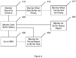
- Figure 4 illustrates a method according to certain embodiments.
- the method can be performed by a user equipment or network element, such as a base station, or eNode B (eNB).
- the method can include, at 410, monitoring a downlink channel, for example a PDCCH, in active time.
- the method can also include, at 420, monitoring an instantaneous status of a data buffer related to a user equipment.
- the monitoring of the downlink channel can be guided by the instantaneous status as presently known.
- the monitoring of the instantaneous status can include, at 425, monitoring for a buffer status report.
- the monitoring the downlink channel can include, at 415, monitoring the downlink channel only when the data buffer is not empty.
- the monitoring of the downlink channel can include, at 417, monitoring the downlink channel only when the data buffer is not empty and a second data buffer related to the user equipment is also not empty.
- the method can include following a discontinuous reception (DRX) on-duration after completing the monitoring of the downlink channel.
- a monitoring length of the monitoring of the downlink channel can be based on a quantity of data in the data buffer.
- the monitoring length can include an on-duration timer or inactivity timer.
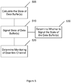
- a method can include, at 510, signaling an instantaneous status of a user equipment data buffer to a network device.
- the signaling the instantaneous state can include signaling the instantaneous state in a buffer status report.
- the instantaneous status can be configured to permit the network device, at 520, to determine monitoring of a downlink channel in active time guided by the instantaneous status as presently known.
- the method can include, at 505, calculating the instantaneous state of the data buffer.
- the method also includes, at 530, determine whether to signal the state of the data buffer. For example, signaling the instantaneous status can be performed when there is a significant change in the buffer status or when synchronization of the buffer status is desired.
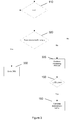
- Figure 6 illustrates a system according to certain embodiments.
- a system may include two devices, user equipment (UE) 610 and eNodeB 620.
- device 610 can be a slave and device 620 can be the master.
- Each of the devices 610 and 620 may be equipped with at least one processor (respectively 614 and 624), at least one memory (respectively 615 and 625) (including computer program instructions or code), a transceiver (respectively 616 and 626), and an antenna (respectively 617 and 627).
- the eNodeB 620 may be equipped for wired communication with a core network (not shown).
- the transceiver (respectively 616 and 626) can be a transmitter, a receiver, both a transmitter and a receiver, or a unit that is configured both for transmission and reception.
- the transceiver (respectively 616 and 626) can be coupled to corresponding one or more antenna(s) (respectively 617 and 627), which may include a directional antenna.
- the at least one processor can be variously embodied by any computational or data processing device, such as a central processing unit (CPU) or application specific integrated circuit (ASIC).
- the at least one processor can be implemented as one or a plurality of controllers.
- the at least one memory can be any suitable storage device, such as a non-transitory computer-readable medium.
- a hard disk drive (HDD) or random access memory (RAM) can be used in the at least one memory (respectively 615 and 625).
- the at least one memory (respectively 615 and 625) can be on a same chip as the corresponding at least one processor (respectively 614 and 624), or may be separate from the corresponding at least one processor (respectively 614 and 624).
- the computer program instructions may be any suitable form of computer program code.
- the computer program instructions may be a compiled or interpreted computer program.
- the at least one memory (respectively 615 and 625) and computer program instructions can be configured to, with the at least one processor (respectively 614 and 624), cause a hardware apparatus (for example, user equipment 610 or eNodeB 620) to perform a process, such as any of the processes described herein (see, for example, Figures 1-5 and 7 ).
- a hardware apparatus for example, user equipment 610 or eNodeB 620
- a non-transitory computer-readable medium can be encoded with computer instructions that, when executed in hardware perform a process, such as one of the processes described herein.
- a process such as one of the processes described herein.
- certain embodiments of the present invention may be performed entirely in hardware.
- each of user equipment 610 and eNodeB 620 can include a user interface that is operable connected to the processor (respectively 614 and 624) and memory (respectively 615 and 625).
- That user interface can include a display, such as a liquid crystal display (LCD) or organic electroluminescent display (OELD), as well as speakers or audio outputs. Tactile outputs, such as a haptic feedback system, can also be included.
- the user interface may have a touch screen to receive user input. User input can also be provided by a keypad, keyboard, microphone, joystick, mouse, trackball, or other input device.
- the eNodeB 620 may be embodied in part as a rack-mounted computer.
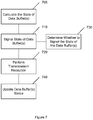
- a method can include, at 710, signaling an instantaneous status of a network device data buffer to a user equipment.
- the signaling the instantaneous state can include signaling the instantaneous state in a buffer status report.
- the instantaneous status can be configured to permit a user equipment to configure monitoring of a downlink channel in active time guided by the instantaneous status as presently known, optionally in combination with an instantaneous status of a user equipment's own buffer status.
- the method can include, at 705, calculating the instantaneous state of the data buffer.
- the method also includes, at 730, determining whether to signal the state of the data buffer. For example, signaling the instantaneous status can be performed when there is a significant change in the buffer status or when synchronization of the buffer status is desired.
- the method also includes, at 720, performing transmission and reception of data with the user equipment.
- This transmission/reception of data can implicitly update a previously provided buffer status report.
- the method can include, at 740, explicitly updating a data buffer status.
- the update can be provided in absolute terms or relative to a previously transmitted buffer status report. Buffer status reports are simply one way that the buffer status can be transmitted, but other ways are also permitted.
Landscapes
- Engineering & Computer Science (AREA)
- Computer Networks & Wireless Communication (AREA)
- Signal Processing (AREA)
- Mobile Radio Communication Systems (AREA)
Claims (14)
- Verfahren, das Folgendes umfasst:Überwachen (410) eines Downlinkkanals in aktiver Zeit oder verbundenem Modus;Empfangen eines momentanen Status eines Datenpuffers einer Basisstation, die mit einer Teilnehmereinrichtung verknüpft ist, in einem Pufferstatusbericht durch die Teilnehmereinrichtung;Überwachen (420) eines momentanen Status von Datenpuffern, die mit der Teilnehmereinrichtung und der Basisstation verknüpft sind,wobei das Überwachen (420) das Überwachen des momentanen Status des Datenpuffers der Basisstation umfasst,das überwachen (410) des Downlinkkanals vom momentanen Status, wie er derzeit bekannt ist, geführt wird unddas überwachen (410, 420) des Downlinkkanals und des momentanen Status der Datenpuffer sowie das Führen der Überwachung des Downlinkkanals in der Teilnehmereinrichtung durchgeführt wird.
- Verfahren nach Anspruch 1, wobei das Überwachen (410) des Downlinkkanals das Überwachen (417) des Downlinkkanals, wenn die Datenpuffer nicht leer sind, umfasst.
- Verfahren nach Anspruch 1 oder Anspruch 2, das ferner Folgendes umfasst:
Überwachen des Downlinkkanals durch die Teilnehmereinrichtung gemäß einem weniger häufigen Muster, wenn die Puffer leer sind. - Verfahren nach einem der Ansprüche 1-3, das ferner Folgendes umfasst:
Folgen (430) einer Einschaltdauer für diskontinuierlichen Empfang, nachdem die Überwachung des Downlinkkanals abgeschlossen wurde. - Verfahren nach einem der Ansprüche 1-4, wobei eine Überwachungslänge der Überwachung des Downlinkkanals auf einer Menge von Daten in den Datenpuffern basiert.
- Verfahren nach Anspruch 5, wobei die Überwachungslänge einen Einschaltdauertimer oder einen Inaktivitätstimer beinhaltet.
- Verfahren, das Folgendes umfasst:Signalisieren eines momentanen Status eines Datenpuffers der Basisstation, die mit einer Teilnehmereinrichtung verknüpft ist, in einem Pufferstatusbericht durch eine Basisstation (710),wobei der momentane Status dazu ausgelegt ist, es der Teilnehmereinrichtung zu erlauben, das Überwachen eines Downlinkkanals in aktiver Zeit, das vom momentanen Status, wie er derzeit bekannt ist, geführt wird, zu bestimmen.
- Verfahren nach Anspruch 7, das ferner Folgendes umfasst:
Berechnen (705) des momentanen Status. - Nichttransitorisches computerlesbares Medium, das mit Anweisungen codiert ist, die, wenn sie in Hardware ausgeführt werden, einen Prozess durchführen, wobei der Prozess das Verfahren nach einem der Ansprüche 1-6 umfasst.
- Nichttransitorisches computerlesbares Medium, das mit Anweisungen codiert ist, die, wenn sie in Hardware ausgeführt werden, einen Prozess durchführen, wobei der Prozess das Verfahren nach Anspruch 7 oder Anspruch 8 umfasst.
- Vorrichtung (610), die Folgendes umfasst:ein Überwachungsmittel (616) zum Überwachen eines Downlinkkanals in aktiver Zeit oder verbundenem Modus undein Empfangsmittel (616) zum Empfangen eines momentanen Status eines Datenpuffers einer Basisstation, die mit einer Teilnehmereinrichtung verknüpft ist, in einem Pufferstatusbericht;ein Überwachungsmittel (614) zum Überwachen eines momentanen Status von Datenpuffern, die mit einer Teilnehmereinrichtung und einer Basisstation verknüpft sind,wobei das Überwachen (614) des momentanen Status das Überwachen des momentanen Status des Datenpuffers der Basisstation umfasst,das Überwachen (616) des Downlinkkanals vom momentanen Status, wie er derzeit bekannt ist, geführt wird unddie Vorrichtung (610) die Teilnehmereinrichtung umfasst.
- Vorrichtung nach Anspruch 11, die ferner ein Mittel zum Durchführen des Verfahrens nach einem der Ansprüche 2-6 umfasst.
- Vorrichtung (620), die Folgendes umfasst:ein Mittel zum Signalisieren eines momentanen Status eines Datenpuffers einer Basisstation, die mit einer Teilnehmereinrichtung verknüpft ist, in einem Pufferstatusbericht durch die Basisstation (626),wobei der momentane Status dazu ausgelegt ist, es der Teilnehmereinrichtung zu erlauben, das Überwachen eines Downlinkkanals in aktiver Zeit, das vom momentanen Status, wie er derzeit bekannt ist, geführt wird, zu bestimmen.
- Vorrichtung nach Anspruch 13, die ferner Folgendes umfasst:
ein Mittel zum Berechnen (624) des momentanen Status.
Applications Claiming Priority (2)
| Application Number | Priority Date | Filing Date | Title |
|---|---|---|---|
| US201261594757P | 2012-02-03 | 2012-02-03 | |
| PCT/FI2013/050019 WO2013113986A1 (en) | 2012-02-03 | 2013-01-10 | Data buffer status influenced control channel monitoring |
Publications (3)
| Publication Number | Publication Date |
|---|---|
| EP2810527A1 EP2810527A1 (de) | 2014-12-10 |
| EP2810527A4 EP2810527A4 (de) | 2015-09-30 |
| EP2810527B1 true EP2810527B1 (de) | 2019-05-15 |
Family
ID=48904455
Family Applications (1)
| Application Number | Title | Priority Date | Filing Date |
|---|---|---|---|
| EP13743147.4A Active EP2810527B1 (de) | 2012-02-03 | 2013-01-10 | Datenpufferstatusbeeinflusste steuerkanalüberwachung |
Country Status (3)
| Country | Link |
|---|---|
| US (1) | US9706422B2 (de) |
| EP (1) | EP2810527B1 (de) |
| WO (1) | WO2013113986A1 (de) |
Families Citing this family (10)
| Publication number | Priority date | Publication date | Assignee | Title |
|---|---|---|---|---|
| US10735982B2 (en) * | 2015-05-15 | 2020-08-04 | Kyocera Corporation | Radio terminal and base station for monitoring a physical downlink control channel during a discontinuous reception operation |
| EP4447374B1 (de) * | 2016-08-10 | 2026-02-25 | InterDigital Patent Holdings, Inc. | Suchraumüberwachung in drahtlosen netzwerken |
| CN113067682B (zh) * | 2017-01-04 | 2023-04-07 | 华为技术有限公司 | 无线通信的方法和设备 |
| WO2019008491A1 (en) * | 2017-07-07 | 2019-01-10 | Telefonaktiebolaget Lm Ericsson (Publ) | METHOD AND NETWORK NODE FOR MONITORING SHORT DOWNLINK COMMAND INFORMATION |
| CN110740025B (zh) | 2018-07-20 | 2021-03-02 | 维沃移动通信有限公司 | 一种信道检测指示方法、终端及网络设备 |
| WO2020060278A1 (ko) * | 2018-09-21 | 2020-03-26 | 엘지전자 주식회사 | 단말의 전력을 절약하는 방법 및 이를 위한 장치 |
| US11228487B2 (en) | 2019-01-28 | 2022-01-18 | Qualcomm Incorporated | Search space configuration for power efficient reception |
| CN113784424B (zh) * | 2019-03-29 | 2023-07-07 | Oppo广东移动通信有限公司 | 一种传输节能信号的方法、基站及终端 |
| WO2020262833A1 (en) * | 2019-06-26 | 2020-12-30 | Lg Electronics Inc. | Method and apparatus for performing discontinuous reception procedure in wireless communication system |
| US20240206005A1 (en) * | 2022-12-14 | 2024-06-20 | Qualcomm Incorporated | Physical downlink control channel monitoring |
Family Cites Families (37)
| Publication number | Priority date | Publication date | Assignee | Title |
|---|---|---|---|---|
| FI20002320A7 (fi) * | 2000-10-20 | 2002-04-21 | Nokia Corp | Eston hallinta langattomissa tietoliikenneverkoissa |
| EP1289328A1 (de) * | 2001-08-28 | 2003-03-05 | Lucent Technologies Inc. | Verfahren zum Senden von Steuerungsinformation in einem drahtlosen Übertragungsnetzwerk und Vorrichtung dafür |
| US7606190B2 (en) * | 2002-10-18 | 2009-10-20 | Kineto Wireless, Inc. | Apparatus and messages for interworking between unlicensed access network and GPRS network for data services |
| US7126928B2 (en) | 2003-08-05 | 2006-10-24 | Qualcomm Incorporated | Grant, acknowledgement, and rate control active sets |
| CN1604687A (zh) * | 2003-08-16 | 2005-04-06 | 三星电子株式会社 | 用于上行链路分组传输的调度分配的方法和装置 |
| EP1854328A2 (de) | 2005-02-28 | 2007-11-14 | Nokia Corporation | Diskontinuierliche(r) übertragung/empfang in einem kommunikationssystem |
| US8094595B2 (en) * | 2005-08-26 | 2012-01-10 | Qualcomm Incorporated | Method and apparatus for packet communications in wireless systems |
| KR20070091068A (ko) * | 2006-03-04 | 2007-09-07 | 삼성전자주식회사 | 무선 망에서 데이터 처리장치 및 방법 |
| US8363605B2 (en) | 2006-08-22 | 2013-01-29 | Qualcomm Incorporated | Method and apparatus for monitoring grant channels in wireless communication |
| EP3589072B1 (de) * | 2007-01-15 | 2021-11-24 | Samsung Electronics Co., Ltd. | Verfahren und vorrichtung zur verarbeitung von uplink-daten durch ein drx-modus-endgerät in einem mobiltelekommunikationssystem |
| WO2008111144A1 (ja) * | 2007-03-09 | 2008-09-18 | Fujitsu Limited | 無線端末の通信制御方法及び無線端末 |
| WO2009022710A1 (ja) * | 2007-08-14 | 2009-02-19 | Ntt Docomo, Inc. | 通信制御方法、移動局、および基地局 |
| EP2068484B1 (de) * | 2007-12-05 | 2016-05-04 | Innovative Sonic Limited | Verfahren und Vorrichtung zur Verbesserung des unterbrochenen Empfangs für ein drahtloses Kommunikationssystem |
| US8175050B2 (en) * | 2008-02-13 | 2012-05-08 | Qualcomm Incorporated | Resource release and discontinuous reception mode notification |
| US8462803B2 (en) * | 2008-05-07 | 2013-06-11 | Telefonaktiebolaget L M Ericsson (Publ) | Discontinuous reception (DRX) timer triggered with the transmission of a buffer status report (BSR) |
| WO2009157826A1 (en) * | 2008-06-24 | 2009-12-30 | Telefonaktiebolaget L M Ericsson (Publ) | Congestion control in a wireless communication network |
| CN101645729A (zh) * | 2008-08-08 | 2010-02-10 | 夏普株式会社 | 下行蜂窝系统的多天线多基站合作方法及基站 |
| KR100937433B1 (ko) * | 2008-09-17 | 2010-01-18 | 엘지전자 주식회사 | 최대 전송 회수를 고려한 harq 동작 방법 |
| CN102217404B (zh) * | 2008-09-19 | 2015-06-10 | 黑莓有限公司 | 半持久性调度激活/重配置信令的检测时间 |
| EP3934336B1 (de) * | 2008-11-10 | 2024-01-03 | Malikie Innovations Limited | Verfahren, vorrichtung und computerlesbares speichermedium zum übergang zu einem batterieeffizienten zustand |
| EP2368398B1 (de) * | 2008-11-25 | 2020-01-08 | InterDigital Patent Holdings, Inc. | Verfahren und vorrichtung zum benutzen mehrerer aufwärtsstreckenträger und mehrerer abwärtsstreckenträger |
| CN101784081B (zh) | 2009-01-21 | 2014-04-16 | 电信科学技术研究院 | 一种配置下行物理控制信道的方法、基站和终端 |
| US8923215B2 (en) * | 2009-02-27 | 2014-12-30 | Qualcomm Incorporated | Method and apparatus for scheduling transmissions in spatial division multiple access network systems |
| US8576714B2 (en) * | 2009-05-29 | 2013-11-05 | Futurewei Technologies, Inc. | System and method for relay node flow control in a wireless communications system |
| KR101607336B1 (ko) * | 2009-06-07 | 2016-03-30 | 엘지전자 주식회사 | 무선 통신 시스템에서 rb 설정 방법 및 장치 |
| CN101925000B (zh) | 2009-06-11 | 2013-11-06 | 电信科学技术研究院 | 一种控制终端监听信道的方法、系统及装置 |
| WO2010151187A1 (en) * | 2009-06-25 | 2010-12-29 | Telefonaktiebolaget L M Ericsson (Publ) | Methods and devices for transmitting a control message |
| KR101164117B1 (ko) * | 2009-09-04 | 2012-07-12 | 엘지전자 주식회사 | 무선 통신 시스템상에서 물리 하향 채널의 모니터링 동작을 효율적으로 제어하는 방법 |
| US9844073B2 (en) * | 2010-01-11 | 2017-12-12 | Qualcomm Incorporated | Methods and apparatus for contention-based uplink access in wireless communication systems |
| US20110261747A1 (en) * | 2010-04-02 | 2011-10-27 | Interdigital Patent Holdings, Inc. | Method and apparatus for supporting communication via a relay node |
| WO2011129582A2 (en) * | 2010-04-12 | 2011-10-20 | Lg Electronics Inc. | Method and apparatus for transmitting and receiving scheduling request using shared resource based filtering in radio communication system |
| US8780860B2 (en) * | 2010-05-01 | 2014-07-15 | Pantech Co., Ltd. | Apparatus and method for transmitting sounding reference signal in wireless communication system supporting multiple component carriers |
| US9642147B2 (en) * | 2011-02-14 | 2017-05-02 | Qualcomm Incorporated | Methods and apparatus for evaluating number of protected active users based on QoS requirements, throughput and traffic |
| US8879667B2 (en) * | 2011-07-01 | 2014-11-04 | Intel Corporation | Layer shifting in open loop multiple-input, multiple-output communications |
| WO2013017154A1 (en) * | 2011-07-29 | 2013-02-07 | Fujitsu Limited | Control channel for wireless communication |
| US8576766B2 (en) * | 2011-08-29 | 2013-11-05 | Telefonaktiebolaget L M Ericsson (Publ) | Dynamic scheduling of in-band relay node resources |
| WO2013112021A1 (ko) * | 2012-01-27 | 2013-08-01 | 삼성전자 주식회사 | 이동통신 시스템에서 복수의 캐리어를 이용해서 데이터를 송수신하는 방법 및 장치 |
-
2013
- 2013-01-10 US US14/372,362 patent/US9706422B2/en active Active
- 2013-01-10 EP EP13743147.4A patent/EP2810527B1/de active Active
- 2013-01-10 WO PCT/FI2013/050019 patent/WO2013113986A1/en not_active Ceased
Non-Patent Citations (1)
| Title |
|---|
| 3GPP: "3rd Generation Partnership Project; Technical Specification Group Radio Access Network; Evolved Universal Terrestrial Radio Access (E-UTRA) and Evolved Universal Terrestrial Radio Access Network (E-UTRAN); Overall description; Stage 2 (Release 11)", 3GPP DRAFT; 36300-B00, 3RD GENERATION PARTNERSHIP PROJECT (3GPP), MOBILE COMPETENCE CENTRE ; 650, ROUTE DES LUCIOLES ; F-06921 SOPHIA-ANTIPOLIS CEDEX ; FRANCE, 21 December 2011 (2011-12-21), XP050563772 * |
Also Published As
| Publication number | Publication date |
|---|---|
| EP2810527A4 (de) | 2015-09-30 |
| WO2013113986A1 (en) | 2013-08-08 |
| EP2810527A1 (de) | 2014-12-10 |
| US9706422B2 (en) | 2017-07-11 |
| US20150009832A1 (en) | 2015-01-08 |
Similar Documents
| Publication | Publication Date | Title |
|---|---|---|
| EP2810527B1 (de) | Datenpufferstatusbeeinflusste steuerkanalüberwachung | |
| KR101709901B1 (ko) | 무선 통신 시스템에서 강화된 사용자 장비 보조 정보를 위한 시스템 및 방법 | |
| US10129830B2 (en) | Systems and methods for enhanced user equipment assistance information in wireless communication systems | |
| JP6172544B2 (ja) | パラメータを設定するための方法、基地局、及びユーザ機器 | |
| EP2742621B1 (de) | Reduzierter signal-overhead während der statusübergänge von funkressourcensteuerungen | |
| EP2832145B1 (de) | Anpassung von mobilitätsparametern auf basis der messungsverfügbarkeit einer benutzervorrichtung | |
| CN105025557B (zh) | 应用与基带层操作之间的协调 | |
| EP2592893A1 (de) | Selbstanpassendes diskontinuierliches Empfangsmuster | |
| KR20120052179A (ko) | 이동통신 시스템에서 단말의 전력 소모를 최적화하는 방법 및 장치 | |
| US10512102B2 (en) | Method and apparatus for triggering an active time to monitor for discontinuous reception | |
| CN111491399B (zh) | 一种非连续传输的处理方法、终端设备和网络设备 | |
| KR102457499B1 (ko) | 지원 정보 시그널링의 네트워크 관리를 위한 방법 및 장치 | |
| JP6414322B2 (ja) | 無線通信システム、無線端末及び無線通信方法 | |
| WO2013190669A1 (ja) | 無線通信システム、無線局、基地局および通信方法 | |
| JP6201257B2 (ja) | 基地局装置、移動局装置および無線通信方法 | |
| HK40115882A (en) | Method and apparatus for triggering an active time to monitor for discontinuous reception | |
| HK1245563B (zh) | 用於无线通信系统中的增强型用户设备辅助信息的系统和方法 | |
| WO2015169353A1 (en) | Uplink grant detection with discontinuous reception |
Legal Events
| Date | Code | Title | Description |
|---|---|---|---|
| PUAI | Public reference made under article 153(3) epc to a published international application that has entered the european phase |
Free format text: ORIGINAL CODE: 0009012 |
|
| 17P | Request for examination filed |
Effective date: 20140801 |
|
| AK | Designated contracting states |
Kind code of ref document: A1 Designated state(s): AL AT BE BG CH CY CZ DE DK EE ES FI FR GB GR HR HU IE IS IT LI LT LU LV MC MK MT NL NO PL PT RO RS SE SI SK SM TR |
|
| AX | Request for extension of the european patent |
Extension state: BA ME |
|
| DAX | Request for extension of the european patent (deleted) | ||
| RAP1 | Party data changed (applicant data changed or rights of an application transferred) |
Owner name: NOKIA TECHNOLOGIES OY |
|
| RA4 | Supplementary search report drawn up and despatched (corrected) |
Effective date: 20150902 |
|
| RIC1 | Information provided on ipc code assigned before grant |
Ipc: H04W 72/12 20090101AFI20150827BHEP Ipc: H04W 24/08 20090101ALI20150827BHEP Ipc: H04W 76/04 20090101ALN20150827BHEP |
|
| STAA | Information on the status of an ep patent application or granted ep patent |
Free format text: STATUS: EXAMINATION IS IN PROGRESS |
|
| 17Q | First examination report despatched |
Effective date: 20180425 |
|
| REG | Reference to a national code |
Ref country code: DE Ref legal event code: R079 Ref document number: 602013055425 Country of ref document: DE Free format text: PREVIOUS MAIN CLASS: H04W0076040000 Ipc: H04W0072120000 |
|
| GRAP | Despatch of communication of intention to grant a patent |
Free format text: ORIGINAL CODE: EPIDOSNIGR1 |
|
| STAA | Information on the status of an ep patent application or granted ep patent |
Free format text: STATUS: GRANT OF PATENT IS INTENDED |
|
| RIC1 | Information provided on ipc code assigned before grant |
Ipc: H04W 76/28 20141210ALN20181106BHEP Ipc: H04W 72/12 20090101AFI20181106BHEP |
|
| INTG | Intention to grant announced |
Effective date: 20181205 |
|
| RIC1 | Information provided on ipc code assigned before grant |
Ipc: H04W 72/12 20090101AFI20181106BHEP Ipc: H04W 76/28 20180101ALN20181106BHEP |
|
| RIC1 | Information provided on ipc code assigned before grant |
Ipc: H04W 72/12 20090101AFI20181106BHEP Ipc: H04W 76/28 20180101ALN20181106BHEP |
|
| GRAS | Grant fee paid |
Free format text: ORIGINAL CODE: EPIDOSNIGR3 |
|
| GRAA | (expected) grant |
Free format text: ORIGINAL CODE: 0009210 |
|
| STAA | Information on the status of an ep patent application or granted ep patent |
Free format text: STATUS: THE PATENT HAS BEEN GRANTED |
|
| AK | Designated contracting states |
Kind code of ref document: B1 Designated state(s): AL AT BE BG CH CY CZ DE DK EE ES FI FR GB GR HR HU IE IS IT LI LT LU LV MC MK MT NL NO PL PT RO RS SE SI SK SM TR |
|
| REG | Reference to a national code |
Ref country code: CH Ref legal event code: EP Ref country code: GB Ref legal event code: FG4D |
|
| RIN1 | Information on inventor provided before grant (corrected) |
Inventor name: VIRTEJ, ELENA Inventor name: DALSGAARD, LARS Inventor name: LUNDEN, PETTERI |
|
| REG | Reference to a national code |
Ref country code: DE Ref legal event code: R096 Ref document number: 602013055425 Country of ref document: DE |
|
| REG | Reference to a national code |
Ref country code: IE Ref legal event code: FG4D |
|
| RAP2 | Party data changed (patent owner data changed or rights of a patent transferred) |
Owner name: NOKIA TECHNOLOGIES OY |
|
| REG | Reference to a national code |
Ref country code: NL Ref legal event code: MP Effective date: 20190515 |
|
| REG | Reference to a national code |
Ref country code: LT Ref legal event code: MG4D |
|
| PG25 | Lapsed in a contracting state [announced via postgrant information from national office to epo] |
Ref country code: AL Free format text: LAPSE BECAUSE OF FAILURE TO SUBMIT A TRANSLATION OF THE DESCRIPTION OR TO PAY THE FEE WITHIN THE PRESCRIBED TIME-LIMIT Effective date: 20190515 Ref country code: ES Free format text: LAPSE BECAUSE OF FAILURE TO SUBMIT A TRANSLATION OF THE DESCRIPTION OR TO PAY THE FEE WITHIN THE PRESCRIBED TIME-LIMIT Effective date: 20190515 Ref country code: NL Free format text: LAPSE BECAUSE OF FAILURE TO SUBMIT A TRANSLATION OF THE DESCRIPTION OR TO PAY THE FEE WITHIN THE PRESCRIBED TIME-LIMIT Effective date: 20190515 Ref country code: HR Free format text: LAPSE BECAUSE OF FAILURE TO SUBMIT A TRANSLATION OF THE DESCRIPTION OR TO PAY THE FEE WITHIN THE PRESCRIBED TIME-LIMIT Effective date: 20190515 Ref country code: FI Free format text: LAPSE BECAUSE OF FAILURE TO SUBMIT A TRANSLATION OF THE DESCRIPTION OR TO PAY THE FEE WITHIN THE PRESCRIBED TIME-LIMIT Effective date: 20190515 Ref country code: LT Free format text: LAPSE BECAUSE OF FAILURE TO SUBMIT A TRANSLATION OF THE DESCRIPTION OR TO PAY THE FEE WITHIN THE PRESCRIBED TIME-LIMIT Effective date: 20190515 Ref country code: SE Free format text: LAPSE BECAUSE OF FAILURE TO SUBMIT A TRANSLATION OF THE DESCRIPTION OR TO PAY THE FEE WITHIN THE PRESCRIBED TIME-LIMIT Effective date: 20190515 Ref country code: PT Free format text: LAPSE BECAUSE OF FAILURE TO SUBMIT A TRANSLATION OF THE DESCRIPTION OR TO PAY THE FEE WITHIN THE PRESCRIBED TIME-LIMIT Effective date: 20190915 Ref country code: NO Free format text: LAPSE BECAUSE OF FAILURE TO SUBMIT A TRANSLATION OF THE DESCRIPTION OR TO PAY THE FEE WITHIN THE PRESCRIBED TIME-LIMIT Effective date: 20190815 |
|
| PG25 | Lapsed in a contracting state [announced via postgrant information from national office to epo] |
Ref country code: LV Free format text: LAPSE BECAUSE OF FAILURE TO SUBMIT A TRANSLATION OF THE DESCRIPTION OR TO PAY THE FEE WITHIN THE PRESCRIBED TIME-LIMIT Effective date: 20190515 Ref country code: GR Free format text: LAPSE BECAUSE OF FAILURE TO SUBMIT A TRANSLATION OF THE DESCRIPTION OR TO PAY THE FEE WITHIN THE PRESCRIBED TIME-LIMIT Effective date: 20190816 Ref country code: BG Free format text: LAPSE BECAUSE OF FAILURE TO SUBMIT A TRANSLATION OF THE DESCRIPTION OR TO PAY THE FEE WITHIN THE PRESCRIBED TIME-LIMIT Effective date: 20190815 Ref country code: RS Free format text: LAPSE BECAUSE OF FAILURE TO SUBMIT A TRANSLATION OF THE DESCRIPTION OR TO PAY THE FEE WITHIN THE PRESCRIBED TIME-LIMIT Effective date: 20190515 |
|
| REG | Reference to a national code |
Ref country code: AT Ref legal event code: MK05 Ref document number: 1134892 Country of ref document: AT Kind code of ref document: T Effective date: 20190515 |
|
| PG25 | Lapsed in a contracting state [announced via postgrant information from national office to epo] |
Ref country code: CZ Free format text: LAPSE BECAUSE OF FAILURE TO SUBMIT A TRANSLATION OF THE DESCRIPTION OR TO PAY THE FEE WITHIN THE PRESCRIBED TIME-LIMIT Effective date: 20190515 Ref country code: RO Free format text: LAPSE BECAUSE OF FAILURE TO SUBMIT A TRANSLATION OF THE DESCRIPTION OR TO PAY THE FEE WITHIN THE PRESCRIBED TIME-LIMIT Effective date: 20190515 Ref country code: SK Free format text: LAPSE BECAUSE OF FAILURE TO SUBMIT A TRANSLATION OF THE DESCRIPTION OR TO PAY THE FEE WITHIN THE PRESCRIBED TIME-LIMIT Effective date: 20190515 Ref country code: EE Free format text: LAPSE BECAUSE OF FAILURE TO SUBMIT A TRANSLATION OF THE DESCRIPTION OR TO PAY THE FEE WITHIN THE PRESCRIBED TIME-LIMIT Effective date: 20190515 Ref country code: DK Free format text: LAPSE BECAUSE OF FAILURE TO SUBMIT A TRANSLATION OF THE DESCRIPTION OR TO PAY THE FEE WITHIN THE PRESCRIBED TIME-LIMIT Effective date: 20190515 Ref country code: AT Free format text: LAPSE BECAUSE OF FAILURE TO SUBMIT A TRANSLATION OF THE DESCRIPTION OR TO PAY THE FEE WITHIN THE PRESCRIBED TIME-LIMIT Effective date: 20190515 |
|
| REG | Reference to a national code |
Ref country code: DE Ref legal event code: R097 Ref document number: 602013055425 Country of ref document: DE |
|
| PG25 | Lapsed in a contracting state [announced via postgrant information from national office to epo] |
Ref country code: IT Free format text: LAPSE BECAUSE OF FAILURE TO SUBMIT A TRANSLATION OF THE DESCRIPTION OR TO PAY THE FEE WITHIN THE PRESCRIBED TIME-LIMIT Effective date: 20190515 Ref country code: SM Free format text: LAPSE BECAUSE OF FAILURE TO SUBMIT A TRANSLATION OF THE DESCRIPTION OR TO PAY THE FEE WITHIN THE PRESCRIBED TIME-LIMIT Effective date: 20190515 |
|
| PLBE | No opposition filed within time limit |
Free format text: ORIGINAL CODE: 0009261 |
|
| STAA | Information on the status of an ep patent application or granted ep patent |
Free format text: STATUS: NO OPPOSITION FILED WITHIN TIME LIMIT |
|
| PG25 | Lapsed in a contracting state [announced via postgrant information from national office to epo] |
Ref country code: TR Free format text: LAPSE BECAUSE OF FAILURE TO SUBMIT A TRANSLATION OF THE DESCRIPTION OR TO PAY THE FEE WITHIN THE PRESCRIBED TIME-LIMIT Effective date: 20190515 |
|
| 26N | No opposition filed |
Effective date: 20200218 |
|
| PG25 | Lapsed in a contracting state [announced via postgrant information from national office to epo] |
Ref country code: PL Free format text: LAPSE BECAUSE OF FAILURE TO SUBMIT A TRANSLATION OF THE DESCRIPTION OR TO PAY THE FEE WITHIN THE PRESCRIBED TIME-LIMIT Effective date: 20190515 |
|
| PG25 | Lapsed in a contracting state [announced via postgrant information from national office to epo] |
Ref country code: SI Free format text: LAPSE BECAUSE OF FAILURE TO SUBMIT A TRANSLATION OF THE DESCRIPTION OR TO PAY THE FEE WITHIN THE PRESCRIBED TIME-LIMIT Effective date: 20190515 |
|
| PG25 | Lapsed in a contracting state [announced via postgrant information from national office to epo] |
Ref country code: MC Free format text: LAPSE BECAUSE OF FAILURE TO SUBMIT A TRANSLATION OF THE DESCRIPTION OR TO PAY THE FEE WITHIN THE PRESCRIBED TIME-LIMIT Effective date: 20190515 |
|
| REG | Reference to a national code |
Ref country code: CH Ref legal event code: PL |
|
| GBPC | Gb: european patent ceased through non-payment of renewal fee |
Effective date: 20200110 |
|
| REG | Reference to a national code |
Ref country code: BE Ref legal event code: MM Effective date: 20200131 |
|
| PG25 | Lapsed in a contracting state [announced via postgrant information from national office to epo] |
Ref country code: FR Free format text: LAPSE BECAUSE OF NON-PAYMENT OF DUE FEES Effective date: 20200131 Ref country code: GB Free format text: LAPSE BECAUSE OF NON-PAYMENT OF DUE FEES Effective date: 20200110 Ref country code: LU Free format text: LAPSE BECAUSE OF NON-PAYMENT OF DUE FEES Effective date: 20200110 |
|
| PG25 | Lapsed in a contracting state [announced via postgrant information from national office to epo] |
Ref country code: BE Free format text: LAPSE BECAUSE OF NON-PAYMENT OF DUE FEES Effective date: 20200131 Ref country code: CH Free format text: LAPSE BECAUSE OF NON-PAYMENT OF DUE FEES Effective date: 20200131 Ref country code: LI Free format text: LAPSE BECAUSE OF NON-PAYMENT OF DUE FEES Effective date: 20200131 |
|
| PG25 | Lapsed in a contracting state [announced via postgrant information from national office to epo] |
Ref country code: IE Free format text: LAPSE BECAUSE OF NON-PAYMENT OF DUE FEES Effective date: 20200110 |
|
| PG25 | Lapsed in a contracting state [announced via postgrant information from national office to epo] |
Ref country code: MT Free format text: LAPSE BECAUSE OF FAILURE TO SUBMIT A TRANSLATION OF THE DESCRIPTION OR TO PAY THE FEE WITHIN THE PRESCRIBED TIME-LIMIT Effective date: 20190515 Ref country code: CY Free format text: LAPSE BECAUSE OF FAILURE TO SUBMIT A TRANSLATION OF THE DESCRIPTION OR TO PAY THE FEE WITHIN THE PRESCRIBED TIME-LIMIT Effective date: 20190515 |
|
| PG25 | Lapsed in a contracting state [announced via postgrant information from national office to epo] |
Ref country code: MK Free format text: LAPSE BECAUSE OF FAILURE TO SUBMIT A TRANSLATION OF THE DESCRIPTION OR TO PAY THE FEE WITHIN THE PRESCRIBED TIME-LIMIT Effective date: 20190515 Ref country code: IS Free format text: LAPSE BECAUSE OF FAILURE TO SUBMIT A TRANSLATION OF THE DESCRIPTION OR TO PAY THE FEE WITHIN THE PRESCRIBED TIME-LIMIT Effective date: 20190915 |
|
| P01 | Opt-out of the competence of the unified patent court (upc) registered |
Effective date: 20230527 |
|
| PGFP | Annual fee paid to national office [announced via postgrant information from national office to epo] |
Ref country code: DE Payment date: 20251203 Year of fee payment: 14 |