EP2810546A1 - Verteilvorrichtung für einzelne Körner - Google Patents
Verteilvorrichtung für einzelne Körner Download PDFInfo
- Publication number
- EP2810546A1 EP2810546A1 EP14170080.7A EP14170080A EP2810546A1 EP 2810546 A1 EP2810546 A1 EP 2810546A1 EP 14170080 A EP14170080 A EP 14170080A EP 2810546 A1 EP2810546 A1 EP 2810546A1
- Authority
- EP
- European Patent Office
- Prior art keywords
- drum
- seal
- disk
- friction insert
- vacuum chamber
- Prior art date
- Legal status (The legal status is an assumption and is not a legal conclusion. Google has not performed a legal analysis and makes no representation as to the accuracy of the status listed.)
- Granted
Links
Images


Classifications
-
- A—HUMAN NECESSITIES
- A01—AGRICULTURE; FORESTRY; ANIMAL HUSBANDRY; HUNTING; TRAPPING; FISHING
- A01C—PLANTING; SOWING; FERTILISING
- A01C7/00—Sowing
- A01C7/04—Single-grain seeders with or without suction devices
- A01C7/042—Single-grain seeders with or without suction devices using pneumatic means
- A01C7/044—Pneumatic seed wheels
- A01C7/046—Pneumatic seed wheels with perforated seeding discs
-
- A—HUMAN NECESSITIES
- A01—AGRICULTURE; FORESTRY; ANIMAL HUSBANDRY; HUNTING; TRAPPING; FISHING
- A01C—PLANTING; SOWING; FERTILISING
- A01C7/00—Sowing
- A01C7/04—Single-grain seeders with or without suction devices
- A01C7/042—Single-grain seeders with or without suction devices using pneumatic means
- A01C7/044—Pneumatic seed wheels
- A01C7/0443—Seed singulators
-
- A—HUMAN NECESSITIES
- A01—AGRICULTURE; FORESTRY; ANIMAL HUSBANDRY; HUNTING; TRAPPING; FISHING
- A01C—PLANTING; SOWING; FERTILISING
- A01C7/00—Sowing
- A01C7/04—Single-grain seeders with or without suction devices
- A01C7/042—Single-grain seeders with or without suction devices using pneumatic means
- A01C7/044—Pneumatic seed wheels
- A01C7/0445—Seed ejectors
Definitions
- the field of the invention is that of the design and production of vacuum seeding planters.
- the invention relates to a device for distributing seeds to the unit of the vacuum type.
- the precision seeding machines 10, such as the one illustrated in figure 1 are traditionally used by farmers to sow the areas they cultivate.
- the seeders generally comprise a frame 12 carried by wheels 13 and intended to be towed or carried by an agricultural machine such as a tractor. They generally comprise several seeding units 11 secured side by side to the frame 12.
- Each seeding unit 11 generally comprises a frame 14 which rests on the ground by means of a pair of gauge wheels 15 between which is placed a pair of opening discs 16.
- a rear block 17, often comprising two inclined wheels, is secured to The back of the frame 14.
- the opening discs open a furrow in the soil when the drill is moved to its surface.
- the gauge wheels adjust the depth of the groove according to their position.
- the rear block allows to close the furrow after seeds have been deposited there.
- Each sowing unit 11 also comprises seed storage means 18, the output of which communicates with a seed distribution device at the unit 19.
- seed dispensing devices in the unit are in particular pneumatic vacuum seed distribution devices with fixed housing.
- the present invention particularly relates to seed dispensers of this type.
- Such a unit seed distribution device comprises conventionally a housing to be fixedly secured to a sowing element.
- This housing comprises a drum and a lid, fixed relative to each other, and together defining an interior cavity.
- a drive shaft is rotatably mounted through the drum. A first end of the drive shaft extends out of the drum while a second end of the drive shaft extends into the cavity.
- a distributor disc traversed by a plurality of seed suction holes formed regularly at its periphery, is mounted to rotate integrally with the drive shaft within the cavity. It defines, with the drum and the cover, a vacuum chamber and a seed tank.
- the drum has a depression opening of the vacuum chamber which is intended to be connected with a device for creating a vacuum such as a turbine 20.
- the shape of the drum is chosen such that a portion of the area of the disk which is traversed by the holes extends outside the vacuum chamber. Part of the disc escapes the depression by turning, which allows to drop the seeds in the furrow.
- the seed distribution per unit is obtained as follows.
- the drive shaft is rotated by means of drive provided for this purpose.
- the distributor disk is then rotated.
- the turbine is used to generate a vacuum inside the vacuum chamber. Seeds are conveyed from seed storage means into the tank. Due to the depression prevailing inside the vacuum chamber, the seeds contained in the tank are sucked up and are positioned one by one on the suction holes of the distributor disk lying opposite the vacuum chamber.
- the disc is equipped with an agitator, consisting of a separate part on which the disc is fixed and which plays the role of stiffening the disc on the one hand, and on the other hand to agitate, to brew the seeds with its wings, which allows to better stall the seeds on the holes.
- Selection means may optionally be implemented to ensure that each hole traps only one seed. As the distributor disc rotates, the suction holes on which a seed is positioned extend outside the vacuum chamber. The seed is then no longer held on the hole and falls off the disk to be routed in the previously opened groove.
- the seeds are deposited in the unit in the groove at regular intervals.
- sealing means are used to ensure the tightness of the vacuum chamber.
- the tightness of the vacuum chamber is obtained by applying the distributor disk against the periphery of the drum.
- the disk is maintained by the depression against the drum and thus ensures the sealing of the vacuum chamber.
- the sealing of the vacuum chamber is obtained by interposing a seal between the distributor disk and the periphery of the drum, this seal being secured to the drum and therefore fixed.
- the disc comes to apply against this seal to seal the vacuum chamber.
- This solution also ensures a good seal of the vacuum chamber. It also helps to overcome the problem of premature wear of the drum and disk inherent in the first solution discussed above. However, because the disk is rubbing against the seal, this seal undergoes a wear that can be fast which requires the implementation of frequent and therefore expensive maintenance campaigns.
- the tightness of the vacuum chamber is obtained by providing a very small clearance between the distributor disk and the periphery of the drum. This ensures the tightness of the vacuum chamber without the distributor disk bears against the drum.
- This solution also ensures a good seal of the vacuum chamber while obviating both the problem of premature wear of the drum and disk inherent in the first solution, as well as that related to the rapid wear to which is subject the seal of the second solution.
- the provision of a sufficiently low clearance between the disk and the drum to seal the vacuum chamber while avoiding contact between the disk and the drum requires compliance with rules of precision engineering design.
- the dispensing devices according to this third solution prove to be difficult and therefore expensive to manufacture.
- the invention particularly aims to overcome these disadvantages of the prior art.
- an object of the invention is to provide a seed dispensing device to the fixed housing vacuum type unit that allows, in at least one embodiment, to optimize the seed distribution.
- the invention has the objective of producing such a device that allows, in at least one embodiment, to ensure a good grip of the seeds in the tank.
- the invention also aims to produce such a device that allows, in at least one embodiment, to release the seeds effectively at the time of their ejection to the ground.
- Another object of the invention is to implement such a device which is, in at least one embodiment, little subject to the phenomenon of wear.
- the invention also aims to produce such a device whose maintenance is, in at least one embodiment, facilitated.
- the invention also aims to produce such a device that allows, in at least one embodiment, to control the friction torque between the disk and the sealing means.
- the invention is based on a completely original approach that consists in sealing the vacuum chamber of a seed distribution device to the fixed box type unit by interposing between the distributor disk and the drum an elastic seal and a friction insert fixed relative to the drum, the seal bearing against the drum and the friction insert, and the friction insert bearing against the distributor disk, the elastic seal now the friction insert bearing against the distributor disk due to its elasticity.
- the distributor disk does not rub against the seal or against the drum during operation of the dispenser. It instead rubs, with a controlled friction torque, against a wear part, in this case the friction insert, provided for this purpose. This avoids the problems of premature wear and consequently limits the maintenance campaigns. Maintenance operations are also facilitated because they are essentially limited to the replacement of the friction insert which, as just indicated, is a wear part.
- said seal has a stiffness such that it exerts on said friction insert a force of between 10N and 100N per linear meter for a compression stroke of the joint of one millimeter.
- a seal exhibiting such elasticity makes it possible to exert a force in support of the friction insert against the disc just needed to guarantee excellent sealing of the vacuum chamber without inducing a major frictional force between the disc and the friction insert. We can then achieve a seed distribution satisfactorily and limit the energy consumption.
- said friction insert comprises an outer peripheral portion in contact with said seal, and an inner peripheral portion, said outer peripheral portion being deformable axially with respect to said inner peripheral portion.
- the outer peripheral portion of the friction insert deforms to come against the distributor disk. This further improves the sealing of the vacuum chamber while having a better control of the friction force between the disc and the friction insert.
- said shaft comprises a shoulder located inside said vacuum chamber, said disk bearing against said shoulder.
- the distributor disk is thus effectively maintained in position even when a vacuum is generated in the vacuum chamber.
- the seal is therefore only related to the force that the seal exerts on the insert and not to a force that would be exerted by the disc on the insert during the depression. This also makes it possible to better control the frictional force between the disk and the insert and in particular to reduce it.
- said friction insert is made of a material with a low coefficient of friction, for example bronze or a plastic material with a Teflon® coating, among others.
- said seal is secured to said drum.
- said seal is secured to said friction insert.
- said seal is preferably secured to said friction insert by gluing, overmolding or clipping in a groove of complementary shape formed in said friction insert.
- the invention discussed also relates to a sowing element comprising a dispensing device according to any one of the variants described above.
- the invention discussed also relates to a drill comprising at least one such sowing element.
- Such a unit seed distribution device comprises a housing intended to be secured in a fixed manner to a sowing element.
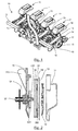
- This housing comprises a drum 30 and a lid 31, fixed relative to each other, and together defining an interior cavity.
- a drive shaft 32 is rotatably mounted through the drum 30.
- a first end 321 of the drive shaft 32 extends out of the drum 30 while a second end 322 of the shaft drive 32 extends inside the cavity.
- a distributor disk 33 traversed by a plurality of seed suction holes 331 formed regularly at its periphery is mounted to rotate with the drive shaft 32 inside the cavity. It defines, with the drum 30 and the lid 31, a vacuum chamber 34 and a seed tank 35.
- the drive shaft 32 includes a shoulder 323 which extends within the dispensing chamber 34. This shoulder 323 may be directly formed in the shaft 32 or may be attached thereto.
- the distributor disc 33 is pressed against the shoulder 323.
- the drum 30 has a depression opening 300 of the vacuum chamber 34 which is intended to be connected with a device for evacuating such as a turbine (not shown).
- the shape of the drum 30 is chosen such that a portion 330 of the zone of the disk 33 which is traversed by the holes 331 extends outside the vacuum chamber 34.
- the contour of the drum 30 thus has a notch 301 .
- a blade stirring disc 36 is mounted to rotate with the shaft inside the tank 35.
- the blades may be welded or molded directly on the distributor disk 33, as long as the disk is sufficiently rigid.
- the distributor disk 33 does not deform, being sufficiently rigid as such and / or being rigid enough because of the blade stirring disc 36. It can not be deformed under the effect of the depression likely to be created in the vacuum chamber 34.
- the cover 31 defines with the disc 33 a zone of ejection of the seeds 37.
- the device comprises sealing means for sealing the vacuum chamber 34.
- These sealing means comprise an elastic seal 38 and a friction insert 39.
- This seal will preferably be made of a plastic material such as an elastomer.
- the friction insert 39 is fixedly mounted relative to the drum 30. It may for example be secured there, preferably in its center, by means of screws or other. It is interposed between the elastic seal 38 and the distributor disc 33. Its shape is defined in such a way that it does not obstruct the suction holes 331 of the disc 33.
- the friction insert 39 comprises an outer peripheral portion 391 in contact with the seal 38, and an inner peripheral portion 392.
- the insert has a certain elasticity so that the outer peripheral portion 391 can deform axially relative to the portion inner peripheral 392 to be pressed against the disc 33 under the effect of the seal 38.
- the outer peripheral portion 391 is connected to the inner peripheral portion 392 by spokes to provide flexibility to the portion outer periphery 391.
- the inner peripheral portion may be fixed to the housing by means of fastening means such as screws or rotational stops or the like, the fixing being to ensure that the inner peripheral portion 392 does not rotate with the disk .
- the friction insert 39 is made of a material with a low coefficient of friction. It may for example be a plastic material, for example coated with Teflon®.
- the elastic seal 38 preferably has a stiffness such that it exerts on the friction insert a force of between 10N and 100N per linear meter for a compression stroke of one millimeter.
- the elastic seal 38 holds the friction insert in abutment against the distributor disc 33.
- Such a dispensing device can be implemented in a sowing element such as those illustrated in FIG. figure 1 .
- a sowing element can be used in a seeder such as that illustrated in FIG. figure 1 .
- the seed distribution per unit is obtained as follows.
- the drive shaft 32 While the seed drill is moved to the ground surface, the drive shaft 32 is rotated by means of drive provided for this purpose.
- the drive shaft 32 may for example wear a ring 40 connected by a chain to the shaft of a motor or a motor shaft (not shown).
- the distributor disc 33 is then rotated in proportion to the forward speed of the drill.
- the turbine 20 is used to generate a vacuum inside the vacuum chamber 34. Seeds are conveyed from the seed storage means of the sowing unit in the reservoir 35. Due to the depression prevailing inside the vacuum chamber 34, the seeds contained in the tank 35 are sucked and are positioned one by one on the suction holes 331 of the distributor disc 33 facing the vacuum chamber 34.
- Selection means 41 may optionally be implemented to ensure that each hole 331 traps only one seed.
- the seeds are deposited individually in the groove at regular intervals.
- the distributor disc 33 Because of its stiffness or its association with an agitator, the distributor disc 33 does not deform under the effect of the depression generated inside the vacuum chamber 34. It is therefore not pressed against the friction insert which limits friction.
- the seal 38 Because of its elasticity, the seal 38 prints the friction insert 39 a force that tends to press and hold it against the disc 33. This ensures a perfect seal of the vacuum chamber 34 without generating a significant frictional force between the friction insert 39 and the distributor disc 33. This friction level depends on the stiffness of the seal 38. The stiffness thereof is chosen so that the sealing of the vacuum chamber ensured by generating as little friction as possible between the disc and the insert.
- the technique according to the invention thus makes it possible to ensure a perfect seal of the vacuum chamber and consequently an optimized seed distribution, while limiting the size of the motor means used to animate the dispenser and reducing the frequency of the campaigns. of maintenance.
- the figure 12 illustrates a partial cross-sectional view of a variant of a seed distributor according to the invention.
- the structure of the seed dispenser according to this variant is identical to that of the seed distributor according to the embodiment just described, except that the elastic seal 38 is no longer integral with the drum 30. It is on the contrary integral with the friction insert 39.
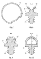
- the seal 38 is clipped into a groove 393 formed for this purpose in the friction insert 39.
- the seal 38 thus preferably comprises a securing portion 383 intended to be inserted by force into the groove 393.
- the seal 38 may be secured to the friction insert 39 by gluing, overmoulding or any other suitable fastening technique.
- the seal 38 bearing against the drum 30, acts against the friction insert 39 to press against the disc 33 with a level of friction just sufficient to ensure the tightness of the vacuum chamber 34
- the wear and the frequency of the maintenance campaigns are thus limited while ensuring an effective sealing of the vacuum chamber and consequently an optimal distribution of the seeds.
- the friction insert may not be secured to the drum. It may instead be mounted floating on the drum in such a way that it is connected to it in rotation but that it can move relative thereto along its longitudinal axis.
- the friction insert may be traversed by longitudinal holes and the drum have axes extending along axes parallel to the axis of the drive shaft. These axes will be inserted into the holes friction insert blocking it in rotation but not in translation.
Landscapes
- Life Sciences & Earth Sciences (AREA)
- Soil Sciences (AREA)
- Environmental Sciences (AREA)
- Sowing (AREA)
Priority Applications (2)
| Application Number | Priority Date | Filing Date | Title |
|---|---|---|---|
| PL14170080T PL2810546T3 (pl) | 2013-06-04 | 2014-05-27 | Urządzenie do indywidualnego dozowania nasion |
| US14/295,995 US9485902B2 (en) | 2013-06-04 | 2014-06-04 | Device for dispensing seeds singly |
Applications Claiming Priority (1)
| Application Number | Priority Date | Filing Date | Title |
|---|---|---|---|
| FR1355138A FR3006145B1 (fr) | 2013-06-04 | 2013-06-04 | Dispositif de distribution de graines a l'unite |
Publications (2)
| Publication Number | Publication Date |
|---|---|
| EP2810546A1 true EP2810546A1 (de) | 2014-12-10 |
| EP2810546B1 EP2810546B1 (de) | 2020-10-14 |
Family
ID=48980110
Family Applications (1)
| Application Number | Title | Priority Date | Filing Date |
|---|---|---|---|
| EP14170080.7A Active EP2810546B1 (de) | 2013-06-04 | 2014-05-27 | Verteilvorrichtung für einzelne Körner |
Country Status (8)
| Country | Link |
|---|---|
| US (1) | US9485902B2 (de) |
| EP (1) | EP2810546B1 (de) |
| DK (1) | DK2810546T3 (de) |
| ES (1) | ES2838688T3 (de) |
| FR (1) | FR3006145B1 (de) |
| HU (1) | HUE052825T2 (de) |
| PL (1) | PL2810546T3 (de) |
| PT (1) | PT2810546T (de) |
Cited By (1)
| Publication number | Priority date | Publication date | Assignee | Title |
|---|---|---|---|---|
| EP4413841A1 (de) | 2023-02-10 | 2024-08-14 | Ribouleau Monosem | Dosiereinheit für eine sämaschine |
Families Citing this family (6)
| Publication number | Priority date | Publication date | Assignee | Title |
|---|---|---|---|---|
| AR098148A1 (es) * | 2014-05-22 | 2016-05-04 | Alberto Gentili Jorge | Dispositivo distribuidor de semillas por accionamiento directo |
| IT201700082167A1 (it) * | 2017-07-19 | 2019-01-19 | Matermacc S P A | Dispositivo distributore di materiale per macchine agricole |
| DE202018006502U1 (de) | 2017-11-10 | 2020-10-28 | Maschio Gaspardo S.P.A. | Säelement für landwirtschaftliche Präzisions-Sämaschinen und für eine Sämaschine mit einem Element dieser Art |
| WO2019092538A1 (en) | 2017-11-10 | 2019-05-16 | Maschio Gaspardo S.P.A. | Sowing element for precision agricultural seeders and seeder including element of this kind |
| CN107593032A (zh) * | 2017-11-15 | 2018-01-19 | 石河子市华农种子机械制造有限公司 | 滚筒式种子包衣机 |
| US11991951B2 (en) | 2021-05-04 | 2024-05-28 | Deere & Company | Agricultural seed loading mechanism for a belted conveyor |
Citations (3)
| Publication number | Priority date | Publication date | Assignee | Title |
|---|---|---|---|---|
| EP0141638A2 (de) * | 1983-10-31 | 1985-05-15 | Deere & Company | Flexible Dichtung für Unterdruck |
| WO1996002123A1 (en) * | 1994-07-14 | 1996-02-01 | Stanhay Webb Limited | Seed dispensing mechanisms |
| WO2012121658A1 (en) * | 2011-03-09 | 2012-09-13 | Väderstad-Verken Ab | Sealing gasket and seed housing for a seeder and seeder comprising such a seed housing |
Family Cites Families (1)
| Publication number | Priority date | Publication date | Assignee | Title |
|---|---|---|---|---|
| US7866525B2 (en) * | 2006-10-06 | 2011-01-11 | Tyco Healthcare Group Lp | Surgical instrument having a plastic surface |
-
2013
- 2013-06-04 FR FR1355138A patent/FR3006145B1/fr not_active Expired - Fee Related
-
2014
- 2014-05-27 DK DK14170080.7T patent/DK2810546T3/da active
- 2014-05-27 HU HUE14170080A patent/HUE052825T2/hu unknown
- 2014-05-27 ES ES14170080T patent/ES2838688T3/es active Active
- 2014-05-27 PL PL14170080T patent/PL2810546T3/pl unknown
- 2014-05-27 EP EP14170080.7A patent/EP2810546B1/de active Active
- 2014-05-27 PT PT141700807T patent/PT2810546T/pt unknown
- 2014-06-04 US US14/295,995 patent/US9485902B2/en active Active
Patent Citations (3)
| Publication number | Priority date | Publication date | Assignee | Title |
|---|---|---|---|---|
| EP0141638A2 (de) * | 1983-10-31 | 1985-05-15 | Deere & Company | Flexible Dichtung für Unterdruck |
| WO1996002123A1 (en) * | 1994-07-14 | 1996-02-01 | Stanhay Webb Limited | Seed dispensing mechanisms |
| WO2012121658A1 (en) * | 2011-03-09 | 2012-09-13 | Väderstad-Verken Ab | Sealing gasket and seed housing for a seeder and seeder comprising such a seed housing |
Cited By (2)
| Publication number | Priority date | Publication date | Assignee | Title |
|---|---|---|---|---|
| EP4413841A1 (de) | 2023-02-10 | 2024-08-14 | Ribouleau Monosem | Dosiereinheit für eine sämaschine |
| FR3145666A1 (fr) | 2023-02-10 | 2024-08-16 | Ribouleau Monosem | Unité de dosage pour une machine d’ensemencement. |
Also Published As
| Publication number | Publication date |
|---|---|
| FR3006145B1 (fr) | 2015-06-26 |
| US9485902B2 (en) | 2016-11-08 |
| US20140352588A1 (en) | 2014-12-04 |
| PL2810546T3 (pl) | 2021-04-06 |
| HUE052825T2 (hu) | 2021-05-28 |
| PT2810546T (pt) | 2021-01-18 |
| DK2810546T3 (da) | 2021-01-11 |
| FR3006145A1 (fr) | 2014-12-05 |
| ES2838688T3 (es) | 2021-07-02 |
| EP2810546B1 (de) | 2020-10-14 |
Similar Documents
| Publication | Publication Date | Title |
|---|---|---|
| EP2810546B1 (de) | Verteilvorrichtung für einzelne Körner | |
| EP0914763B1 (de) | Scheibenschar für Sämaschine | |
| FR2961058A1 (fr) | Semoir mono-graine comprenant une chambre a depression incluant des moyens additionnels de maintien en appui d'un disque obturateur contre un disque distributeur | |
| EP2145775B1 (de) | Halbhohlreifen und entsprechende Radfelge, insbesondere für Landwirtschaftsmaschinen | |
| EP3017669B1 (de) | Verbessertes rad für landwirtschaftliche verwendung | |
| EP3834594A1 (de) | Abstreiferrad für sämaschine | |
| FR2762907A1 (fr) | Dispositif pour mesurer la rotation d'un element tournant | |
| EP2359672B1 (de) | Säeinheit mit einem spitzen Element zwischen zwei Öffnungsscheiben einer Furche und Mittel zum Freigeben des Elements ohne Abmontieren der Scheiben | |
| EP2823701A1 (de) | Säelement mit Griff zum Einstellen des Senkdrucks, und entsprechender Griff | |
| FR2854025A1 (fr) | Machine agricole realisant simultanement la pose de film plastique et l'ensemencement dite "machine plastisemeuse" et module d'ensemencement | |
| FR2905558A1 (fr) | Piece d'usure protegeant un outil de travail et sa fixation avec boutonniere, corps de labour comportant un tel outil et charrue comportant un corps de labour | |
| EP0462033A1 (de) | Pneumatische Einzelkorndrillmaschine | |
| FR3159074A1 (fr) | Dispositif de dosage de particules à épandre à boisseau rotatif amélioré, et machine agricole correspondante | |
| FR2916657A1 (fr) | Dispositif d'obturation d'une buse de distribution de fluide | |
| EP0682854B1 (de) | Landwirtschaftliche Bodenbearbeitungswalze und Landmaschine mit einer solchen Walze | |
| FR3164875A1 (fr) | Ensemble pour un semoir comprenant au moins un élément semeur, dispositif de rangement d’une porte et semoir associés | |
| EP4684624A1 (de) | Trennvorrichtung für ein verteilungselement und zugehörige sämaschine | |
| EP0132207A2 (de) | Einzelkorndrillelement für Sonderanbau wie Gartenbau, Gemüsebau oder Baumschulen | |
| FR2993749A1 (fr) | Herisson pour epandeur | |
| EP2636291B1 (de) | Selbstregulierende Befestigungsvorrichtung einer Ausstattung auf dem Fahrgestell einer Sämaschine | |
| EP0392890A1 (de) | Silofutterschneider und Schneidvorrichtung für Futter, insbesondere Silofutter | |
| EP2656717A1 (de) | Flexible Übertragungsvorrichtung, die Versteifungsmittel in einer ersten Richtung aber nicht in einer zweiten Richtung umfasst | |
| FR2880420A1 (fr) | Aiguille a bord contraste pour compteur ou similaire, et procede de fabrication d'une telle aiguille | |
| BE694678A (de) | ||
| FR3018994A1 (fr) | Dispositif de distribution rotative pour planteuse |
Legal Events
| Date | Code | Title | Description |
|---|---|---|---|
| PUAI | Public reference made under article 153(3) epc to a published international application that has entered the european phase |
Free format text: ORIGINAL CODE: 0009012 |
|
| 17P | Request for examination filed |
Effective date: 20140527 |
|
| AK | Designated contracting states |
Kind code of ref document: A1 Designated state(s): AL AT BE BG CH CY CZ DE DK EE ES FI FR GB GR HR HU IE IS IT LI LT LU LV MC MK MT NL NO PL PT RO RS SE SI SK SM TR |
|
| AX | Request for extension of the european patent |
Extension state: BA ME |
|
| R17P | Request for examination filed (corrected) |
Effective date: 20150311 |
|
| RBV | Designated contracting states (corrected) |
Designated state(s): AL AT BE BG CH CY CZ DE DK EE ES FI FR GB GR HR HU IE IS IT LI LT LU LV MC MK MT NL NO PL PT RO RS SE SI SK SM TR |
|
| STAA | Information on the status of an ep patent application or granted ep patent |
Free format text: STATUS: EXAMINATION IS IN PROGRESS |
|
| 17Q | First examination report despatched |
Effective date: 20190625 |
|
| GRAP | Despatch of communication of intention to grant a patent |
Free format text: ORIGINAL CODE: EPIDOSNIGR1 |
|
| STAA | Information on the status of an ep patent application or granted ep patent |
Free format text: STATUS: GRANT OF PATENT IS INTENDED |
|
| INTG | Intention to grant announced |
Effective date: 20200430 |
|
| GRAS | Grant fee paid |
Free format text: ORIGINAL CODE: EPIDOSNIGR3 |
|
| GRAA | (expected) grant |
Free format text: ORIGINAL CODE: 0009210 |
|
| STAA | Information on the status of an ep patent application or granted ep patent |
Free format text: STATUS: THE PATENT HAS BEEN GRANTED |
|
| AK | Designated contracting states |
Kind code of ref document: B1 Designated state(s): AL AT BE BG CH CY CZ DE DK EE ES FI FR GB GR HR HU IE IS IT LI LT LU LV MC MK MT NL NO PL PT RO RS SE SI SK SM TR |
|
| REG | Reference to a national code |
Ref country code: GB Ref legal event code: FG4D Free format text: NOT ENGLISH |
|
| REG | Reference to a national code |
Ref country code: AT Ref legal event code: REF Ref document number: 1322633 Country of ref document: AT Kind code of ref document: T Effective date: 20201015 Ref country code: CH Ref legal event code: EP |
|
| REG | Reference to a national code |
Ref country code: DE Ref legal event code: R096 Ref document number: 602014071166 Country of ref document: DE |
|
| REG | Reference to a national code |
Ref country code: IE Ref legal event code: FG4D Free format text: LANGUAGE OF EP DOCUMENT: FRENCH |
|
| REG | Reference to a national code |
Ref country code: NL Ref legal event code: FP |
|
| REG | Reference to a national code |
Ref country code: DK Ref legal event code: T3 Effective date: 20210104 |
|
| REG | Reference to a national code |
Ref country code: PT Ref legal event code: SC4A Ref document number: 2810546 Country of ref document: PT Date of ref document: 20210118 Kind code of ref document: T Free format text: AVAILABILITY OF NATIONAL TRANSLATION Effective date: 20210112 |
|
| PG25 | Lapsed in a contracting state [announced via postgrant information from national office to epo] |
Ref country code: NO Free format text: LAPSE BECAUSE OF FAILURE TO SUBMIT A TRANSLATION OF THE DESCRIPTION OR TO PAY THE FEE WITHIN THE PRESCRIBED TIME-LIMIT Effective date: 20210114 Ref country code: RS Free format text: LAPSE BECAUSE OF FAILURE TO SUBMIT A TRANSLATION OF THE DESCRIPTION OR TO PAY THE FEE WITHIN THE PRESCRIBED TIME-LIMIT Effective date: 20201014 Ref country code: FI Free format text: LAPSE BECAUSE OF FAILURE TO SUBMIT A TRANSLATION OF THE DESCRIPTION OR TO PAY THE FEE WITHIN THE PRESCRIBED TIME-LIMIT Effective date: 20201014 Ref country code: GR Free format text: LAPSE BECAUSE OF FAILURE TO SUBMIT A TRANSLATION OF THE DESCRIPTION OR TO PAY THE FEE WITHIN THE PRESCRIBED TIME-LIMIT Effective date: 20210115 |
|
| REG | Reference to a national code |
Ref country code: LT Ref legal event code: MG4D |
|
| REG | Reference to a national code |
Ref country code: HU Ref legal event code: AG4A Ref document number: E052825 Country of ref document: HU |
|
| PG25 | Lapsed in a contracting state [announced via postgrant information from national office to epo] |
Ref country code: LV Free format text: LAPSE BECAUSE OF FAILURE TO SUBMIT A TRANSLATION OF THE DESCRIPTION OR TO PAY THE FEE WITHIN THE PRESCRIBED TIME-LIMIT Effective date: 20201014 Ref country code: IS Free format text: LAPSE BECAUSE OF FAILURE TO SUBMIT A TRANSLATION OF THE DESCRIPTION OR TO PAY THE FEE WITHIN THE PRESCRIBED TIME-LIMIT Effective date: 20210214 Ref country code: SE Free format text: LAPSE BECAUSE OF FAILURE TO SUBMIT A TRANSLATION OF THE DESCRIPTION OR TO PAY THE FEE WITHIN THE PRESCRIBED TIME-LIMIT Effective date: 20201014 Ref country code: BG Free format text: LAPSE BECAUSE OF FAILURE TO SUBMIT A TRANSLATION OF THE DESCRIPTION OR TO PAY THE FEE WITHIN THE PRESCRIBED TIME-LIMIT Effective date: 20210114 |
|
| PG25 | Lapsed in a contracting state [announced via postgrant information from national office to epo] |
Ref country code: HR Free format text: LAPSE BECAUSE OF FAILURE TO SUBMIT A TRANSLATION OF THE DESCRIPTION OR TO PAY THE FEE WITHIN THE PRESCRIBED TIME-LIMIT Effective date: 20201014 |
|
| REG | Reference to a national code |
Ref country code: ES Ref legal event code: FG2A Ref document number: 2838688 Country of ref document: ES Kind code of ref document: T3 Effective date: 20210702 |
|
| REG | Reference to a national code |
Ref country code: DE Ref legal event code: R097 Ref document number: 602014071166 Country of ref document: DE |
|
| PG25 | Lapsed in a contracting state [announced via postgrant information from national office to epo] |
Ref country code: SK Free format text: LAPSE BECAUSE OF FAILURE TO SUBMIT A TRANSLATION OF THE DESCRIPTION OR TO PAY THE FEE WITHIN THE PRESCRIBED TIME-LIMIT Effective date: 20201014 Ref country code: RO Free format text: LAPSE BECAUSE OF FAILURE TO SUBMIT A TRANSLATION OF THE DESCRIPTION OR TO PAY THE FEE WITHIN THE PRESCRIBED TIME-LIMIT Effective date: 20201014 Ref country code: LT Free format text: LAPSE BECAUSE OF FAILURE TO SUBMIT A TRANSLATION OF THE DESCRIPTION OR TO PAY THE FEE WITHIN THE PRESCRIBED TIME-LIMIT Effective date: 20201014 Ref country code: EE Free format text: LAPSE BECAUSE OF FAILURE TO SUBMIT A TRANSLATION OF THE DESCRIPTION OR TO PAY THE FEE WITHIN THE PRESCRIBED TIME-LIMIT Effective date: 20201014 Ref country code: SM Free format text: LAPSE BECAUSE OF FAILURE TO SUBMIT A TRANSLATION OF THE DESCRIPTION OR TO PAY THE FEE WITHIN THE PRESCRIBED TIME-LIMIT Effective date: 20201014 |
|
| PLBE | No opposition filed within time limit |
Free format text: ORIGINAL CODE: 0009261 |
|
| STAA | Information on the status of an ep patent application or granted ep patent |
Free format text: STATUS: NO OPPOSITION FILED WITHIN TIME LIMIT |
|
| 26N | No opposition filed |
Effective date: 20210715 |
|
| PG25 | Lapsed in a contracting state [announced via postgrant information from national office to epo] |
Ref country code: AL Free format text: LAPSE BECAUSE OF FAILURE TO SUBMIT A TRANSLATION OF THE DESCRIPTION OR TO PAY THE FEE WITHIN THE PRESCRIBED TIME-LIMIT Effective date: 20201014 |
|
| PG25 | Lapsed in a contracting state [announced via postgrant information from national office to epo] |
Ref country code: SI Free format text: LAPSE BECAUSE OF FAILURE TO SUBMIT A TRANSLATION OF THE DESCRIPTION OR TO PAY THE FEE WITHIN THE PRESCRIBED TIME-LIMIT Effective date: 20201014 |
|
| PG25 | Lapsed in a contracting state [announced via postgrant information from national office to epo] |
Ref country code: LU Free format text: LAPSE BECAUSE OF NON-PAYMENT OF DUE FEES Effective date: 20210527 Ref country code: MC Free format text: LAPSE BECAUSE OF FAILURE TO SUBMIT A TRANSLATION OF THE DESCRIPTION OR TO PAY THE FEE WITHIN THE PRESCRIBED TIME-LIMIT Effective date: 20201014 |
|
| PG25 | Lapsed in a contracting state [announced via postgrant information from national office to epo] |
Ref country code: IS Free format text: LAPSE BECAUSE OF FAILURE TO SUBMIT A TRANSLATION OF THE DESCRIPTION OR TO PAY THE FEE WITHIN THE PRESCRIBED TIME-LIMIT Effective date: 20210214 |
|
| REG | Reference to a national code |
Ref country code: AT Ref legal event code: UEP Ref document number: 1322633 Country of ref document: AT Kind code of ref document: T Effective date: 20201014 |
|
| PG25 | Lapsed in a contracting state [announced via postgrant information from national office to epo] |
Ref country code: CY Free format text: LAPSE BECAUSE OF FAILURE TO SUBMIT A TRANSLATION OF THE DESCRIPTION OR TO PAY THE FEE WITHIN THE PRESCRIBED TIME-LIMIT Effective date: 20201014 |
|
| PG25 | Lapsed in a contracting state [announced via postgrant information from national office to epo] |
Ref country code: MK Free format text: LAPSE BECAUSE OF FAILURE TO SUBMIT A TRANSLATION OF THE DESCRIPTION OR TO PAY THE FEE WITHIN THE PRESCRIBED TIME-LIMIT Effective date: 20201014 |
|
| PGFP | Annual fee paid to national office [announced via postgrant information from national office to epo] |
Ref country code: IE Payment date: 20240527 Year of fee payment: 11 |
|
| PGFP | Annual fee paid to national office [announced via postgrant information from national office to epo] |
Ref country code: GB Payment date: 20240527 Year of fee payment: 11 |
|
| PGFP | Annual fee paid to national office [announced via postgrant information from national office to epo] |
Ref country code: DK Payment date: 20240527 Year of fee payment: 11 |
|
| PGFP | Annual fee paid to national office [announced via postgrant information from national office to epo] |
Ref country code: CH Payment date: 20240602 Year of fee payment: 11 |
|
| PGFP | Annual fee paid to national office [announced via postgrant information from national office to epo] |
Ref country code: AT Payment date: 20240503 Year of fee payment: 11 |
|
| PGFP | Annual fee paid to national office [announced via postgrant information from national office to epo] |
Ref country code: PT Payment date: 20240506 Year of fee payment: 11 |
|
| PGFP | Annual fee paid to national office [announced via postgrant information from national office to epo] |
Ref country code: HU Payment date: 20240509 Year of fee payment: 11 Ref country code: BE Payment date: 20240527 Year of fee payment: 11 |
|
| PG25 | Lapsed in a contracting state [announced via postgrant information from national office to epo] |
Ref country code: MT Free format text: LAPSE BECAUSE OF FAILURE TO SUBMIT A TRANSLATION OF THE DESCRIPTION OR TO PAY THE FEE WITHIN THE PRESCRIBED TIME-LIMIT Effective date: 20201014 |
|
| PGFP | Annual fee paid to national office [announced via postgrant information from national office to epo] |
Ref country code: NL Payment date: 20250526 Year of fee payment: 12 |
|
| PGFP | Annual fee paid to national office [announced via postgrant information from national office to epo] |
Ref country code: PL Payment date: 20250505 Year of fee payment: 12 Ref country code: DE Payment date: 20250423 Year of fee payment: 12 |
|
| PGFP | Annual fee paid to national office [announced via postgrant information from national office to epo] |
Ref country code: ES Payment date: 20250602 Year of fee payment: 12 |
|
| PGFP | Annual fee paid to national office [announced via postgrant information from national office to epo] |
Ref country code: IT Payment date: 20250521 Year of fee payment: 12 |
|
| PGFP | Annual fee paid to national office [announced via postgrant information from national office to epo] |
Ref country code: FR Payment date: 20250526 Year of fee payment: 12 |
|
| PGFP | Annual fee paid to national office [announced via postgrant information from national office to epo] |
Ref country code: TR Payment date: 20250515 Year of fee payment: 12 |
|
| PGFP | Annual fee paid to national office [announced via postgrant information from national office to epo] |
Ref country code: CZ Payment date: 20250507 Year of fee payment: 12 |
|
| PG25 | Lapsed in a contracting state [announced via postgrant information from national office to epo] |
Ref country code: PT Free format text: LAPSE BECAUSE OF NON-PAYMENT OF DUE FEES Effective date: 20251127 |
|
| REG | Reference to a national code |
Ref country code: DK Ref legal event code: EBP Effective date: 20250531 |
|
| REG | Reference to a national code |
Ref country code: CH Ref legal event code: H13 Free format text: ST27 STATUS EVENT CODE: U-0-0-H10-H13 (AS PROVIDED BY THE NATIONAL OFFICE) Effective date: 20251223 |
|
| PG25 | Lapsed in a contracting state [announced via postgrant information from national office to epo] |
Ref country code: AT Free format text: LAPSE BECAUSE OF NON-PAYMENT OF DUE FEES Effective date: 20250527 |
|
| PG25 | Lapsed in a contracting state [announced via postgrant information from national office to epo] |
Ref country code: HU Free format text: LAPSE BECAUSE OF NON-PAYMENT OF DUE FEES Effective date: 20250528 |
|
| REG | Reference to a national code |
Ref country code: AT Ref legal event code: MM01 Ref document number: 1322633 Country of ref document: AT Kind code of ref document: T Effective date: 20250527 |
|
| PG25 | Lapsed in a contracting state [announced via postgrant information from national office to epo] |
Ref country code: CH Free format text: LAPSE BECAUSE OF NON-PAYMENT OF DUE FEES Effective date: 20250531 |
|
| GBPC | Gb: european patent ceased through non-payment of renewal fee |
Effective date: 20250527 |
|
| REG | Reference to a national code |
Ref country code: BE Ref legal event code: MM Effective date: 20250531 |
|
| PG25 | Lapsed in a contracting state [announced via postgrant information from national office to epo] |
Ref country code: GB Free format text: LAPSE BECAUSE OF NON-PAYMENT OF DUE FEES Effective date: 20250527 |
|
| PG25 | Lapsed in a contracting state [announced via postgrant information from national office to epo] |
Ref country code: IE Free format text: LAPSE BECAUSE OF NON-PAYMENT OF DUE FEES Effective date: 20250527 Ref country code: DK Free format text: LAPSE BECAUSE OF NON-PAYMENT OF DUE FEES Effective date: 20250531 |
|
| PG25 | Lapsed in a contracting state [announced via postgrant information from national office to epo] |
Ref country code: BE Free format text: LAPSE BECAUSE OF NON-PAYMENT OF DUE FEES Effective date: 20250531 |