EP2810552A1 - Mat de retenue d'une feuille hydro-absorbante - Google Patents
Mat de retenue d'une feuille hydro-absorbante Download PDFInfo
- Publication number
- EP2810552A1 EP2810552A1 EP12867329.0A EP12867329A EP2810552A1 EP 2810552 A1 EP2810552 A1 EP 2810552A1 EP 12867329 A EP12867329 A EP 12867329A EP 2810552 A1 EP2810552 A1 EP 2810552A1
- Authority
- EP
- European Patent Office
- Prior art keywords
- mat
- water absorbent
- absorbent sheet
- retaining
- slit
- Prior art date
- Legal status (The legal status is an assumption and is not a legal conclusion. Google has not performed a legal analysis and makes no representation as to the accuracy of the status listed.)
- Withdrawn
Links
Images




























Classifications
-
- A—HUMAN NECESSITIES
- A01—AGRICULTURE; FORESTRY; ANIMAL HUSBANDRY; HUNTING; TRAPPING; FISHING
- A01K—ANIMAL HUSBANDRY; AVICULTURE; APICULTURE; PISCICULTURE; FISHING; REARING OR BREEDING ANIMALS, NOT OTHERWISE PROVIDED FOR; NEW BREEDS OF ANIMALS
- A01K1/00—Housing animals; Equipment therefor
- A01K1/01—Removal of dung or urine ; Removal of manure from stables
- A01K1/0107—Cat trays; Dog urinals; Toilets for pets
-
- A—HUMAN NECESSITIES
- A01—AGRICULTURE; FORESTRY; ANIMAL HUSBANDRY; HUNTING; TRAPPING; FISHING
- A01K—ANIMAL HUSBANDRY; AVICULTURE; APICULTURE; PISCICULTURE; FISHING; REARING OR BREEDING ANIMALS, NOT OTHERWISE PROVIDED FOR; NEW BREEDS OF ANIMALS
- A01K1/00—Housing animals; Equipment therefor
- A01K1/015—Floor coverings, e.g. bedding-down sheets ; Stable floors
- A01K1/0157—Mats; Sheets
Definitions
- the present invention relates to a mat used for retaining a water absorbent sheet, and more particularly, to a water absorbent sheet retaining mat for retaining a water absorbent sheet for a pet.
- a sheet having a capacity to absorb or soak up water (hereinafter referred to as a "water absorbent sheet") is laid on an object which would be suffered from being wet such as a floor or a table for protecting it from the water.
- a liquid amount to be absorbed exceeds the capacity of the water absorbent sheet or when the water absorbent sheet shifts from the proper position.
- Typical cases of such shifts are that a pet moves the water absorbent sheet during feeding or excreting thereon. The water absorbent sheet which is broken by the pet comes upon the same situation in which the liquid amount to be absorbed exceeds the capacity thereof.
- a toilet mat for a pet is proposed by Patent Literature 1 for proactively counter the above cases.
- the toilet mat for a pet proposed by Patent Literature 1 is used in a state in which a toilet sheet for a pet is laid on an upper surface thereof.
- the toilet mat for a pet 1001 includes a main body formed in almost a rectangular shape, and a pair of fixtures 1011a and 1011b for retaining the toilet sheet for a pet 1002 on the main body.
- the main body is made with a material, preferably has water repellency, which is well durable and easy to change the shape for convenience of carrying.
- magnets 112 to the main body, and magnets 111 to the fixtures 1011a and 1011b are provided with magnets 112 to the main body, and magnets 111 to the fixtures 1011a and 1011b.
- the toilet sheet for a pet 1002 in the toilet mat for a pet 1001 is made in a manner below.
- the fixtures 1011a and 1011b are located in the positions over the laid sheet 1002 so that the magnets 111 position above the magnets 112. Then, the fixtures 1011a and 1011b are let down toward the main body so that the magnets 111 and 112 stick to each other.
- An attraction force working between the magnets 111 and 112 generates a frictional force between the toilet sheet 1002 and the magnets 111 and 112.
- the toilet sheet 1002 is fixed on and retained by the toilet mat for a pet 1001 by the frictional force.
- the toilet sheet 1002 can be removed from the main body after the fixtures 1011a and 1011b are detached from the main body.
- the fixtures 1011a and 1011b when the magnets 111 and 112 are not provided therein, press the toilet sheet 1002 against the toilet mat for a pet 1001 by the self weight thereof, causing the frictional force between the toilet sheet 1002 and the fixtures 1011a and 1011b to fix the toilet sheet 1002 thereat.
- the frictional force is increased by increasing the weight of the fixtures 1011a and 1011b to increase the fixing force of the toilet sheet 1002.
- the magnets 111 and 112 are provided, it is devised to increase the magnetism thereof to increase the frictional force.
- Patent Literature 1 Japanese Patent Application Laid-Open No. 2007-110929
- Patent Literature 1 discloses a toilet mat for a pet which forces a user to remove and install fixtures every time to get on and off a toilet sheet.
- the fixtures are separately provided from the main body of toilet mat, and are placed on a toilet sheet when in use. Thus, the fixtures would become dirty by pet's excrements, and cleaning is required. There is a possibility that the fixtures, separately provided from the main body of the toilet mat, are lost during cleaning the fixtures or exchanging the toilet sheet.
- the magnets are provided as a means for positioning the fixtures on the main body of the toilet mat
- the magnets provided in the main body of the toilet mat sit under the toilet sheet, disabling the user to visually observe thereof during the installation of the fixtures.
- the toilet sheet should be greater than the distance between the magnets to be fixed on the toilet mat by the fixtures, limiting the size of toilet sheet could be used.
- the weight of fixtures is increased, lessened is the portability of the toilet mat as well as increased is the load to the operator during the installation or uninstallation of the fixtures.
- strengthening of the magnets will not affect the portability of the toilet mat, a high-strength magnetism makes the working load of installing or removing the fixtures heavier and requires a consideration of the influence on the magnetic products therearound.
- an object of the present invention is to provide a water absorbent sheet retaining mat which can retain a water absorbent sheet easily and surely.
- the water absorbent sheet retaining mat for retaining a water absorbent sheet having a first polygonal contour comprises a mat member having a second polygonal contour defined by mutually opposing a first main plane and a second main plane; and at least one retaining member having a slit member comprised of at least one slit formed in a top surface at a first predetermined height from the first main plane for accepting a part of perimeter of the water absorbent sheet being inserted therein, wherein the water absorbent sheet is laid on the first main plane.
- the present invention can provide a water absorbent sheet retaining mat which can retain a water absorbent sheet easily and surely.
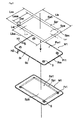
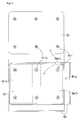
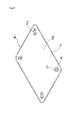
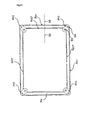
- the water absorbent sheet retaining mat M aiming to be able to retain a water absorbent sheet having a predetermined polygonal contour easily and surely, includes a mat member Pm with a plane St on which a water absorbent sheet Sa is laid (hereinafter referred to as a "laying plane St"), and a retaining member Pr which retains the water absorbent sheet Sa.
- the mat member Pm has a predetermined polygonal contour and is formed in a flat plate like shape having a thickness t1 and being defined by the laying plane St which is the first main plane and the second main plane Sb opposed to and apart from the first main plane St by a predetermined distance t1.
- the second main plane Sb (hereinafter referred to as a "sitting plane Sb") of the mat member Pm is a plane which contacts a place where the water absorbent sheet retaining mat M is sit.
- At least one of the retaining member Pr, formed in a block like shape having a predetermined height t2, is provided on the laying plane St or adjacent to the mat member Pm.
- the water absorbent sheet Sa and the mat member Pm each could be formed in arbitrary shapes other than a rectangular shape depicted in Fig. 1 .
- the mat member Pm is basically configured to have an inner shape greater than an outer shape of the water absorbent sheet Sa.
- the retaining member Pr is provided so as to be located in a position inner by a predetermined distance L ( Fig. 3 ) from an outer perimeter of the water absorbent sheet Sa when the water absorbent sheet Sa is laid on the laying plane St.
- the water absorbent sheet Sa and the mat member Pm are described as being formed in a rectangular shape as shown in Fig. 1 for convenience of explanation in this specification. In this case, the water absorbent sheet Sa should be laid on the mat such that at least one portion of the tips of four corners thereof would be inserted in the cut S by the predetermined length L.
- the retaining members Pr (the fixtures) with the cut S formed in the top surface thereof are provided not separately from the mat member Pm (a toilet mat for a pet) but in a position above the laying plane St of the mat member Pm.
- the mat member Pm a toilet mat for a pet
- both the cut S and the to-be inserted portion of the water absorbent sheet Sa can be visually observed without difficulty and the working of retaining (insertion) of the water absorbent sheet Sa can be carried out easily and surely. Further, the water absorbent sheet Sa is pinched by the cut S provided in the retaining member Pr at the top surface where the friction with the water absorbent sheet Sa is produced, and is retained. Thus, no weight increasing of the fixtures or magnetism strengthening for securing enough retaining force is necessary.
- the retaining members Pr can be provided in any position as long as they can be located inner area of the water absorbent sheet Sa; the mat member Pm is basically bigger than the water absorbent sheet Sa to be retained, and is therefore formed as bigger than the biggest one of the water absorbent sheet Sa; the retaining members Pr are arranged in an area corresponding to the water absorbent sheet Sa in a size range from the biggest size to the smallest.
- a single of the mat member Pm can retain any of the water absorbent sheet Sa in all sizes.
- the water absorbent sheet retaining mat M is constructed of a waterproof and flexible material.
- the waterproofness is required for preventing a liquid from permeating, and the flexibility is required for surely and stably retaining the water absorbent sheet Sa by being deformed along a shape of the place on which the water absorbent sheet retaining mat M is laid.
- safety and corrosion proof is preferably required for the material of which the water absorbent sheet retaining mat M is made. The safety comes from a consideration of that a pet may lick the water absorbent sheet retaining mat M used for the same purposes as the conventional toilet mat for a pet. The corrosion proof is for withstanding the applied liquid (such as a pet's urine and so on).
- the water absorbent sheet retaining mat M is implemented of silicon rubber.
- a water absorbent sheet retaining mat according to a first embodiment of the present invention is described below.
- Fig. 2 shows a state in which a water absorbent sheet retaining mat M1 is used.
- the water absorbent sheet retaining mat M1 has a construction similar to that of the water absorbent sheet retaining mat M except that the mat member Pm and the retaining member Pr are replaced with a mat member Pm1 and a retaining member Pr1, respectively.
- the mat member Pm1 and the retaining member Pr1 are intensively described below.
- the mat member Pm1 is integrally provided with a mat frame member Rm vertically extending from an edge of the laying plane St of the mat member Pm by a predetermined height H1.
- the mat member Pm1 is formed in a pan-like shape with the laying plane St and the mat frame member Rm corresponding to a bottom and a circumferential wall, respectively. Thanks to this pan-like construction, the mat member Pm1 can hold a liquid not absorbed by the water absorbent sheet inside.
- the mat member Pm1 can be made by adhering the mat frame member Rm and the retaining member Pr to the mat member Pm, but more preferably by integrally forming the mat member Pm and the retaining member Pr.
- the retaining members Pr1 have a construction similar to that of the retaining members Pr except the arrangements in the mat member Pm1.
- the arrangement of retaining members Pr1 are determined according to the construction of the water absorbent sheet Sa1 to be retained. Therefore, before describing the arrangement of the retaining members Pr1, the construction of the water absorbent sheet Sa1 is explained below.
- the water absorbent sheet Sa1 includes an area served for water absorption (hereinafter referred to as an "absorption area" Spa and a sheet brim member Spr.
- the absorption area Spa has a polygonal contour smaller than that of the water absorbent sheet Sa1, and is provided substantially at the center thereof.
- a width of the sheet brim member Spr, a distance between the absorption area Spa and the outer perimeter of the water absorbent sheet Sa1 is designated as a sheet brim width Lpr.
- the absorption area Spa is formed in a rectangular shape defined by a short side Lssa and a long side Llsa.
- the sheet brim member Spr is provided to surround the absorption area Spa.
- the water absorbent sheet Sa1 is constructed with a front surface made of a liquid permeable material such as a nonwoven fabrics, and a back surface made of a liquid non-permeable material such as nylon and a vinyl. Included in the absorption area Spa is an absorbent material such as a high polymer.
- the water absorbent sheet Sa1 As the water absorbent sheet Sa1, suitable goods on the market can be used.
- the water absorbent sheets Sa1 in the regular size have the outer contours as large as about a rectangular whose short side Lss is 310mm to 330mm, and long side Lls is 440mm to 450mm.
- the water absorbent sheets Sa1 in the wide size have the outer contours as large as about a rectangular whose short side Lss is 430mm to 450mm, and long side Lls is 590mm to 600mm.
- the width Lpr of the sheet brim member Spr is about 20mm to 30mm.
- the absorption area Spa is located such that the center point thereof is common with the outer contour of the water absorbent sheet Sa1.
- the water absorbent sheet Sa1 has 4 corner portions Spc.
- a line connecting corner ridges of the absorption area Spa and the water absorbent sheet Sa1 is designated as a connection line Lar, and a length thereof is designated as a separation distance Dar.
- the retaining member Pr1 is preferably located in the below described position when the water absorbent sheet Sa1 is laid on the laying plane St.
- the center of the retaining member Pr1 (a slit member S) is preferably located in the position corresponding to the corner of the absorption area Spa each.
- the retaining member Pr1 is provided on such a position that the absorption area Spa on the front surface of the water absorbent sheet Sa1 is not covered with the retaining member Pr1 when the water absorbent sheet Sa1 constructed as above is laid with the back surface thereof in contact with the laying plane St of the mat member Pm1. Specifically, firstly, the back surface of the water absorbent sheet Sa1 is laid on the laying plane St of the mat member Pm1. Then, at least a part of the corner portion Spc of the water absorbent sheet Sa1 is inserted in the slit member S of the retaining member Pr1. By being the corner portion Spc inserted in the slit member S, the water absorbent sheet Sa1 is positioned and retained on the water absorbent sheet retaining mat M1. Note that the sheet brim member Spr whose portions, not being caught by the slit member S, hang down so as to contact with the laying plane St, and then rise up from and surround the absorption area Spa.
- the positions in which the retaining members Pr1 are arranged is determined in consideration of that the effect of the sheet brim member Spr rising from and surrounding the absorption area Spa to suppress the splash from the absorption area Spa or to the case when the liquid falls in a direction not perpendicular to the absorption area Spa.
- At least one of the retaining members Pr1 is enough for retaining the water absorbent sheet Sa1 on the water absorbent sheet retaining mat M1.
- the edge of water absorbent sheet Sa1 is preferably retained.
- the mat member Pm1 is constructed to have the inner shape greater than the outer shape of the water absorbent sheet Sa1.
- the following equations (1) and (2) are satisfied.
- the retaining members Pr1 are provided so as to be located in the positions inner by the predetermined distance L from an outer perimeter of the water absorbent sheet Sa1 when the water absorbent sheet Sa1 is laid on the laying plane St.
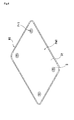
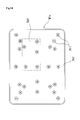
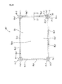
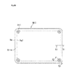
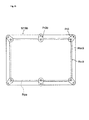
- 4 pieces of the retaining member Pr1 are provided on the laying plane St so as to be located substantially on the diagonal lines of the mat member Pm1.
- Each of the four retaining members Pr1 is located in the position corresponding to each of the four corner portions Spc, when the water absorbent sheet Sa1 is laid on the laying plane St.
- the retaining member Pr1 has an external appearance of a cylinder like shape and rises almost perpendicularly from the laying plane St at a predetermined height t2 ( Fig. 1 ). Formed in a top surface Sru of the retaining member Pr1 is the slit member S in which a part of the water absorbent sheet Sa1 will be inserted. A distance between the centers of neighboring two retaining members Pr1 is substantially the same as either of the short side Lssa and the long side Llsa of the absorption area Spa in the water absorbent sheet Sa1.
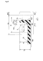
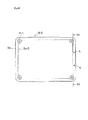
- Fig. 5 is an enlarged plan view showing an encircled portion V in Fig. 3 , and also showing an example of the retaining member of the water absorbent sheet retaining mat for a pet;
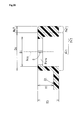
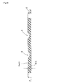
- Fig. 6 shows a cross sectional construction taken along a line VI-VI in Fig. 5 ; and
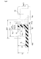
- Fig. 7 shows the slit member of the retaining member of Fig.6 on an enlarged scale.
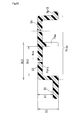
- Fig. 8 shows a cross sectional construction of an alternative example of the retaining member in Fig. 5 ; and
- Fig. 9 shows the slit member of the retaining member of Fig.8 on an enlarged scale.
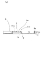
- the retaining member Pr1 is defined by an inner diameter Di, an outer diameter Do, and the height t2, and is composed of a peripheral wall Wr formed in a tubular shape and the top surface Sru.
- the inner diameter Di of the retaining member Pr1 should be about as large as to accept the user's finger therein.
- the height t2 of the retaining member Pr1 is about equal to the height H1 of the mat frame member Rm (hereinafter referred to as "mat frame height H1").
- the inner and outer diameters Di and Do of the retaining member Pr1 are set to 24mm and 30mm, respectively.
- the slit member S is comprised of 3 slits SL1, SL2, and SL3 intersecting each other ( Fig. 7 ).
- the slits SL1, SL2, and SL3 define 6 pieces of claws Psru in the top surface Sru.
- the length and width of slits SL1, SL2, and SL3 are set to about 22mm and about 0.5mm to 1mm, respectively.
- An end portions Pes in the distal ends of each slit in the longitudinal direction is formed in a circular arc shape having a radius of curvature R.
- a circular step Sc ( Fig. 7 ) having a predetermined height tc ( Fig. 6 ) between the end portions Pes of each of the slits SL1, SL2, and SL3 and the peripheral wall Wr.
- the step Sc increases the thickness of intermediate portion between the peripheral wall Wr and the root (girth) of the claws Psru, functioning to reinforce a structural strength of the retaining member Pr1.
- the end portions Pes are prevented from being lacerated by suppressing excessive deformation of the claws Psru when the water absorbent sheet Sa1 is inserted in or removed from the slit member S, ensuring the installation and uninstallation of the water absorbent sheet Sa1. Even if any laceration occurs in the end portion Pes, such laceration is prevented from growing.
- the retaining member Pr1 is made of flexible material, the user can easily insert an edge of the water absorbent sheet Sa1 into the slit member S comprised of the slits SL1, SL2, and SL3.
- the water absorbent sheet Sa1 is retained by the top surfaces Sru due to a friction force working between the inserted edge of water absorbent sheet Sa1 and the plural claws Psru.
- the end portion Pes of each slit is formed in a circular arc shape having a predetermined radius of curvature R, the retaining member Pr1 is hardly lacerated in the root of claw Psru even if the water absorbent sheet Sa1 is installed and uninstalled repeatedly.
- the step Sc is not always necessary, if the retaining member Pr or the claw Psru is strong enough.
- the example shown in Fig. 8 and Fig. 9 is constructed such that the claws Psru of the retaining member Pr1 already described with reference to Fig. 5 , Fig. 6 , and Fig. 7 are connected to each other at the underside thereof by a rim Sr.
- the rim Sr is also cut and divided by three very fine slits SL1, SL2, and SL3.
- the claw Psru is provided with the rim Sr on two sides thereof.
- the rim Sr reinforces the claw Psru as well as reduces a gap between neighboring claws Psru. Resultantly, an excessive deformation of claws Psru when the water absorbent sheet Sa1 is inserted therein or thereout is prevented, making sure the installation and uninstallation of the water absorbent sheet Sa1.
- rim Sr is not always necessary, if the retaining member Pr1 or the claw Psru is strong enough. It is allowed to provide both the step Sc and the rim Sr on a single of retaining member Pr1.
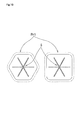
- the retaining member Pr1 (or the peripheral wall Wr) should be in a tubular shape, but in any shape comprised of a top surface wherein the slit member S is provided and a side wall supporting the top surface.
- the retaining member Pr1 may be formed in a prism having a polygon base, for example, such as a rectangle or a hexagon, as shown in Fig. 10 .
- the number of slits defining the slit member S is not limited to three, and any number is acceptable if the slit member S can hold the water absorbent sheet Sa1 by plural number of the claws Psru. More specifically, one slit is enough to define the slit member S, and then the maximum number of slit can be properly determined in consideration of the required strength and the material of the top surface Sru.
- a water absorbent sheet retaining mat M1a is used for retaining two regular sized water absorbent sheets Sala and Sa1b laid on the laying plane St with a portion thereof being overlapped.
- the water absorbent sheet retaining mat M1a can be used for retaining a single of wide sized water absorbent sheet laid on the laying plane St.
- the water absorbent sheet retaining mat M1a has a construction similar to that of the water absorbent sheet retaining mat M1 except that the mat member Pm1 is replaced with a mat member Pm1a and a retaining member Pr1a is additionally provided.
- the mat member Pm1a and the retaining member Pr1a are intensively described below.
- Arrangement of the retaining members Pr1 and the retaining members Pr1a is determined according to the construction of two water absorbent sheets Sala and Sa1b to be retained.
- Four pieces of retaining members Pr1 are arranged in the positions corresponding to two pieces of the corner portions Spc of the water absorbent sheet Sala and two pieces of the corner portions Spc of the water absorbent sheet Sa1b when the water absorbent sheets Sala and Sa1b are laid on the laying plane St.
- the retaining member Pr1a is provided in a position corresponding about a center on a line connecting the neighboring retaining members Pr1 and Pr1.
- the water absorbent sheets Sala and Sa1b are installed in the water absorbent sheet retaining mat M1a in a following manner.
- the water absorbent sheet Sala is held such that four corner portions Spc are caught by two retaining members Pr1 and two retaining members Pr1a.
- the water absorbent sheet Sa1b is held such that four corner potions Spc thereof is caught by two retaining members Pr1 and two retaining members Pr1a.
- a single of wide sized water absorbent sheet is installed in the water absorbent sheet retaining mat M1a in a following manner.
- the water absorbent sheet is held such that four retaining members Pr1 catch the four corner portions Spc and two retaining members Pr1a catch the longer sides at about center positions thereof.
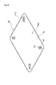
- a water absorbent sheet retaining mat M1b is constructed by modifying the water absorbent sheet retaining mat M1, already described with reference to Fig. 3 and Fig. 4 , such that a plurality of retaining members Pr1 are provided on the diagonal lines Lo of the mat member Pm1. Thanks to this construction, the water absorbent sheet Sa1 in various sizes can be retained by the same water absorbent sheet retaining mat M1b. If the water absorbent sheet Sa1 is a toilet or litter sheet for a pet, the water absorbent sheet Sa1 in a larger size can be used according to the growth of pet.
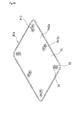
- a water absorbent sheet retaining mat M1c is constructed by modifying the water absorbent sheet retaining mat M1b described with reference to Fig. 13 such that a plurality of retaining members Pr1 are additionally provided in positions other than the diagonal lines Lo. Thanks to this construction, the water absorbent sheet Sa1 in various sizes can be retained by the same water absorbent sheet retaining mat M1c in different position and in various directions.
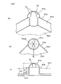
- a water absorbent sheet retaining mat M1d according to this alternative embodiment has a construction similar to that of the water absorbent sheet retaining mat M1 shown in Fig.3 except that the retaining member Pr1 is replaced with a retaining member Pr1c.
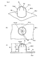
- FIG. 77(a) shown is a perspective view of the water absorbent sheet retaining mat M1d focused on the retaining member Pr1c.
- Fig. 77(b) shown is a plan view of the water absorbent sheet retaining mat M1d looking down a top surface of the retaining member Pr1c.
- Fig. 77(c) shown is a side view of the water absorbent sheet retaining mat M1d focused on the retaining member Pr1c.
- the slit member S extends flat. More specifically, a plurality of claws Psru extend horizontally at the height t2.
- the retaining member Pr1c is provided with a three-dimensionally formed, or dome-shaped slit member Sd instead of the slit member S, as shown in Fig. 77 .
- the slit member Sd is, as shown in Fig. 77(b) , divided into a plurality of claws Psrud in a three-dimensional shape by slits SL as the slit member S is.
- the slit member Sd has a vertex (a tapered end of the claw Psrud) at the height t2 and a bottom (base of the claw Psrud) at a predetermined height t2b (t2>t2b).
- the claw Psrud projects upward from the top of peripheral wall Wr by a predetermined distance L2. That is, a top part of the peripheral wall Wr in a tubular shape forms the dome-shaped slit member Sd (claw Psrud).
- the water absorbent sheet Sa is installed in the water absorbent sheet retaining mat M1d in a following manner. At least a portion of apexes of four corners of water absorbent sheet Sa is inserted into the slit member S by a predetermined length L measured from the top end of the slit member Sd (vertexes of claws Psrud). In contrast that the claw Psru is formed flat, the claw Psrud is formed convex in the top side and concave in the underside. Thanks to this construction, when the water absorbent sheet Sa is inserted in the retaining member Pr1c from a top surface Srud thereof, the claws Psrud easily deform downward (to the mat member Pm1).
- the claws Psrud when pulling up the inserted water absorbent sheet Sa to remove from the retaining member Pr1c, the claws Psrud shall be forcibly deformed upward (in a direction for everting the claw Psrud). This is efficacious to prevent accidental removal of the water absorbent sheet Sa which is once installed.
- the claws Psrud project upward (to an open space) by the predetermined distance L2 from the open end (upper end) of the peripheral wall Wr forming an enclosed space.
- the edge portion of the water absorbent sheet Sa into the slit member Sd, it is possible to deform the claw Psrud downward by pushing thereof down by the predetermined distance L2 without being obstructed by the peripheral wall Wr.
- a water absorbent sheet retaining mat M2 shown in Fig. 15 and Fig. 16 has the construction similar to that of the water absorbent sheet retaining mat M1 described in the above except that the mat member Pm1 and the retaining member Pr1 are replaced with a mat member Pm2 and a retaining member Pr2, respectively.
- the two retaining members Pr1 are arranged to be adjacent to each other.
- a path connecting two retaining members Pr1 is provided in the water absorbent sheet retaining mat M2.
- the mat member Pm2 and the retaining member Pr2 are intensively described below.
- a slit member S1 is provided in a top surface Sru1 supported by a tubular peripheral wall Wr1 defined by an inner diameter Di1 and an outer diameter Do1 ( Fig. 17 ).
- a slit member S2 is provided in a top surface Sru2 supported by a tubular peripheral wall Wr2 defined by an inner diameter Di2 and an outer diameter Do2 ( Fig. 17 ).
- the slit members S1 and S2 are arranged such that the centers thereof are located on the diagonal line of the mat member Pm2 and the peripheral walls Wr1 and Wr2 make a point contact. That is, the retaining member Pr2 according to the present embodiment is constructed of two of the retaining members Pr1 (the first embodiment) provided on the diagonal line such that the peripheral walls Wr1 and Wr2 have contact with each other.
- Fig. 17 shown is a plan view of the retaining member Pr2 seen from the sitting plane Sb side of the mat member Pm2.
- the peripheral wall Wr1 and the peripheral wall Wr2 are arranged to be adjacent to each other. Note that a step Sc1 is provided between the peripheral wall Wr1 and claws Psru1, and a step Sc2 is provided between the peripheral wall Wr2 and claws Psru2, as in the retaining member Pr1 described in the above.
- a path Pas is formed such that the adjacent area of the peripheral walls Wr1 and Wr2 as well as the mat member Pm2 under the adjacent area are removed from the sitting place Sb to the under sides of the top surfaces of Sru1 and Sru2. Note that the claws Psru1 and the claws Psru2 are surrounded by the step Sc1 and the step Sc2, respectively.
- space defined by the peripheral wall Wr1 communicates with space defined by the peripheral wall Wr2 via the path Pas.
- the claws Psru1 and the claws Psru2 are provided with the step Sc1 and the step Sc2, respectively.
- the provision of the steps Sc1 and Sc2 compensates for a decrease in strength of the retaining member Pr2 due to the partial removal of the peripheral walls Wr1 and Wr2 to form the path Pas.
- the inner diameters Di1 and Di2 of the peripheral walls Wr1 and Wr2 should be about as large as to accept a finger of a person (a user of the water absorbent sheet retaining mat) therein.
- the inner diameters Di1 and Di2 have a relationship of Di1>Di2 in the example shown in the figures, but not limited thereto.
- the path Pas is wide enough to allow an edge of the water absorbent sheet Sa1 to pass therethrough.
- the location of the slit member S1 on the mat member Pm2 is determined similarly as the location of the slit member S of the retaining member Pr1. That is, a distance between the centers of neighboring two slit members S1 and S1 is substantially the same as either of the short side Lssa and the long side Llsa of the absorption area Spa in the water absorbent sheet Sa1.
- the slit member S2 is located in a position adjacent to the slit member S1 and shifted from the slit member S1 toward the centrifugal direction (close to the side of outer contour of the water absorbent sheet Sa1).
- the water absorbent sheet Sa1 is laid on the laying plane St of the mat member Pm2 with the back side down. Then, at least a part of the corner portion Spc of the water absorbent sheet Sa1 is inserted in the slit member S1 of the retaining member Pr2. Next, the corner portion Spc inserted in the slit member S1 is drawn through the path Pas. Then, the corner portion Spc is inserted in the slit member S2 from the side of the sitting plane Sb toward the side of the laying plane St. Fig.
- FIG. 17 shows the example in which the inner diameters Di1 and Di2 are set to have a relationship of Di1>Di2, in consideration of the fact that an edge of the sheet brim member Spr (the water absorbent sheet Sa1) is inserted in the slit member S2 and a portion of the sheet brim member Spr adjacent to the absorption area Spa is inserted in the slit member S1.
- the above-described procedures will be described in detail with reference to Fig. 26 .
- the steps Sc1 and Sc2 are not always necessary, if the retaining member Pr2 or the claws Psru1 and Psru2 are strong enough.
- either or both of the slit member S1 and the slit member S2 in the retaining member Pr2 can be provided with the rim Sr described with reference to Fig. 5 , Fig. 8 , and Fig. 9 .
- a water absorbent sheet retaining mat M2a is used for retaining two regular sized water absorbent sheets Sala and Sa1b laid on the laying plane St with a portion thereof being overlapped.
- the water absorbent sheet retaining mat M2a can be used for retaining a single of wide sized water absorbent sheet laid on the laying plane St.
- the water absorbent sheet retaining mat M2a has a construction similar to that of the water absorbent sheet retaining mat M2 except that the mat member Pm2 is replaced with a mat member Pm2a and a retaining member Pr2a is additionally provided.
- the mat member Pm2a and the retaining member Pr2a are intensively described below.
- Arrangement of the retaining members Pr2 and the retaining members Pr2a is determined according to the construction of two water absorbent sheets Sala and Sa1b to be retained.
- Four pieces of retaining members Pr2 are arranged such that their respective slit members S1 are located in the positions corresponding to two pieces of corner portions Spc of the water absorbent sheet Sala and two pieces of corner portions Spc of the water absorbent sheet Sa1b when the water absorbent sheets Sala and Sa1b are laid on the laying plane St.
- the retaining members Pr2a are provided such that their respective slit members S1 are located in the positions corresponding about a center on a line connecting the slit members S1 of the neighboring retaining members Pr2 and Pr2.
- the slit members S2 are located adjacent to the slit members S1 and shifted from the slit members S1 toward the centrifugal direction (close to the side of outer contour of the water absorbent sheet Sa1).
- a water absorbent sheet retaining mat according to a third embodiment of the present invention is described below.
- Fig. 27 shows a state in which a water absorbent sheet retaining mat M3 is used.
- the water absorbent sheet retaining mat M3 has a construction similar to that of the water absorbent sheet retaining mat M2 described in the above except that the mat member Pm2 and the retaining member Pr2 are replaced with a mat member Pm3 and a retaining member Pr3, respectively.
- the mat member Pm3 and the retaining member Pr3 are intensively described below.
- the retaining member Pr3 is constructed such that a plurality of (two, for example) slit members S3 and S4 are integrally provided. Thanks to this construction, a distance between the centers of the slit members S3 and S4 is smaller than a distance between the centers of the slit members S1 and S2 of the retaining member Pr2 described in the above, thereby ensuring a sufficient length of a portion of the water absorbent sheet Sa1 (the sheet brim member Spr) to be inserted in the slit member S4 located outside.
- the slit members S3 and S4 are arranged to be adjacent to each other, sharing a portion of their respective peripheral walls Wr3 and Wr4.
- the distance between the centers of the slit members is made small by a length of the shared portion of the peripheral wall Wr3 (or the peripheral wall Wr4).
- the overall strength of the peripheral wall Wr3 and peripheral wall Wr4 is somewhat lower than that of the peripheral wall Wr1 and peripheral wall Wr2 in the second embodiment, due to sharing the portion thereof.
- Fig. 23 shown is the retaining member Pr3, looked from the side of the sitting place Sb of the mat member Pm3.
- the peripheral wall Wr3 and the peripheral wall Wr4 share a portion. This shared portion is partially removed from the sitting plane Sb of the mat member Pm3 to the underside of top surfaces Sru3 and Sru4, forming the path Pas ( Fig. 24 ).
- Fig. 25 wherein a cross sectional shape of the retaining member Pr3 taken along a line perpendicular to the path Pas is shown, recognized are the wall Wb1, a shared portion Wrc, and the wall Wb2.
- a truss is constructed with the wall Wb1 and the shared portion Wrc as well as between the shared portion Wrc and the wall Wb2 a truss is constructed with the shared portion Wrc and the wall Wb2, as shown in Fig. 23 .
- This truss structure reinforces the retaining member Pr3.
- the truss structures with the wall Wb1 and the shared portion Wrc as well as with the shared portion Wrc and the wall Wb2
- Fig. 26 the installation procedures of the water absorbent sheet Sa1 is illustrated in 4 phases P1, P2, P3, and P4. Firstly, in the first phase P1, the water absorbent sheet Sa1 is placed on the laying plane St of the mat member Pm3. The corner tip of the sheet brim member Spr of the water absorbent sheet Sa1 is inserted in the slit member S3 from the top surface Sru3 of the retaining member Pr3.
- the mat member Pm3 is bent up so as to turn up the sitting plane Sb. Then, the tip of the sheet brim member Spr, being inserted from the top surface Sru3, is pulled out from the slit member S3 until the corner of the absorption area Spa gets close to the center of the slit member S3.
- the tip of sheet brim member Spr being pulled out is led to the side of slit member S4 through the path Pas. Then, the tip of the sheet brim member Spr is pushed into the slit member S4.
- the mat member Pm3 bent up in the second phase P2 is unbend so as to turn up the side of laying plane St. Then, the tip of the sheet brim member Spr being pushed into the slit member S4 in the third phase is pulled up from the top surface of the slit member S4 such that the sheet brim member Spr is accommodated in the path Pas.
- the water absorbent sheet Sa1 is installed in the mat member Pm3 such that the sheet brim member Spr is standing around the absorption area Spa.
- the sheet brim member Spr pulled to the sitting plane Sb side is accommodated in the path Pas and will not be an obstacle to that the mat member Pm3 (sitting plane Sb) sit on a floor or a table where the mat member Pm3 is laid.
- the sheet brim member Spr will not deform the mat member Pm3.
- the water absorbent sheet retaining mat M3 (the mat member Pm3) is placed along the floor or the table, and is free from deforming the water absorbent sheet Sa1 being installed therein and sliding on the floor or the table.
- a water absorbent sheet retaining mat M3a is constructed by modifying the water absorbent sheet retaining mat M2a described with reference to Fig. 18 and Fig. 19 , such that the retaining members Pr2 are replaced with the retaining members Pr3.
- a water absorbent sheet retaining mat M3b is constructed by modifying the water absorbent sheet retaining mat M3 described with reference to Fig. 20 and Fig. 21 , such that a plurality of retaining members Pr3 are provided on the diagonal lines Lo of the mat member Pm3. This enables the retaining of the water absorbent sheets Sa1 of different sizes by the same water absorbent sheet retaining mat M3b. Furthermore, the water absorbent sheet Sa1, when used for collecting pet's excreta, of much greater size according to the pet's growth can be installed.
- a water absorbent sheet retaining mat M3c is constructed by modifying the water absorbent sheet retaining mat M3b described with reference to Fig. 31 such that a plurality of retaining members Pr3 are additionally provided in other positions than on the diagonal lines Lo.
- Water absorbent sheets Sa1 of different sizes can be installed in the mat member Pm3 of the same water absorbent sheet retaining mat M3c in different poses and positions.
- a water absorbent sheet retaining mat M4 has a construction similar to that of the above described water absorbent sheet retaining mat M1 except that the mat member Pm1 is replaced with a mat member Pm4.
- the mat member Pm4 is configured to have an outer shape smaller than an outer shape of the water absorbent sheet Sa1.
- the retaining member Pr1 is provided adjacent to or close to an outer perimeter of the mat member Pm4 such that the top surface Sru is located above the laying plane St.
- the water absorbent sheet Sa1 can also be installed in the mat member Pm4 smaller than the mat member Pm1. It is allowed to construct such that the retaining member Pr1 and the outer perimeter of the mat member Pm4 share a portion of peripheral walls thereof in a manner described in the above with reference to Fig. 22 . It is allowed to provide the retaining members Pr2 and Pr3 adjacent to or close to outer perimeters of the mat member Pm2 and Pm3 with any of the water absorbent sheet retaining mats M2, M2a, M3, M3a, M3b, and M3c according to the second and third embodiments and the alternative embodiments thereof, as in the present embodiment.
- a water absorbent sheet retaining mat M5 is provided with the retaining member Pr1 adjacent to or close to the inner periphery of the mat frame member Rm of the mat member Pm4 of the above described water absorbent sheet retaining mat M4. Resultantly, the water absorbent sheet retaining mat M5 can retain the water absorbent sheet Sa1 whose absorption area Spa is rather smaller than that the water absorbent sheet retaining mat M4 can retain.
- a water absorbent sheet retaining mat M6 according to this embodiment is devised such that the openings in the sitting planes Sb of the retaining members Pr1, Pr2, and Pr3 of the water absorbent sheet retaining mats M1, M1a, M1b, M1c, M2, M2a, M3, M3a, M3b, and M3c according to the above described first, second, and third embodiments and the alternative embodiment are closed. Specifically, the opening are closed by a cap C fitting into the inner shape of the opening or peripheral wall Wr to be closed.
- FIG. 35 shown is a state in which the opening of the retaining member Pr1 of the water absorbent sheet retaining mat M1 depicted in Fig. 8 is closed by the cap C. This will enable that an excessive amount of the liquid which the absorption area Spa could not absorb is prevented from trespassing the mat member Pm1 through the slit member S to soak the place such as table where the water absorbent sheet retaining mat M1 is placed.
- the inside of the cap C is washable by water supplied and discharged through the slit member S. Furthermore, the cap C can be removed from the opening for being water washed as needed.
- a water absorbent sheet retaining mat according to a seventh embodiment of the present invention.
- the water absorbent sheet retaining mat M7 according to this embodiment in comparison to the water absorbent sheet retaining mat M1 according to the first embodiment described with reference to Fig. 2 to Fig. 9 .
- the mat frame member Rm is provided over the entire perimeter of the mat member Pm1.
- the retaining members Pr1 On the laying plane St of the mat member Pm1, provided are the retaining members Pr1.
- a retaining member Pr7 is not provided on the laying plane St but provided integrally with a mat frame member Rm7 formed in the perimeter of the mat member Pm7 as shown in Fig. 36 .
- the peripheral member of the retaining member Pr7 is preferably formed in a gentle shape defined by a predetermined radius of curvature R.
- a center axis of the slit member S perpendicular to the top surface Sru of the retaining member Pr7 is regarded as a slit center axis Acs ( Fig. 37 )
- a two-dot chain line connecting the slit center axes Acs define a rectangular region Rpa.
- the corner of absorption area Spa of water absorbent sheet Sa1 is located at the center of slit member S and then the water absorbent sheet Sa1 is retained by the mat member Pm7 such that the sheet brim member Spr around the absorption area Spa stands up.
- the contour of the region Rpa corresponds to a boundary line between the absorption area Spa retained in a flat state and the sheet brim member Spr retained in a standing state, while the water absorbent sheet Sa1 installed.
- the region Rpa is called a water absorption region Rpa
- a region between the water absorption region Rpa and the mat frame member Rm7 is called a sheet brim standing region Rpr.
- the retaining member Pr7 is formed bigger than the retaining member Pr1 only by an outer perimeter Pe7 thereof.
- the retaining member Pr7 is constructed such that an circular contour of the retaining member Pr1 confines itself within the circular contour of the retaining member Pr7, and shifts toward the center of the water absorbent sheet retaining mat M7 within the circular contour of the retaining member Pr7.
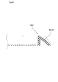
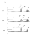
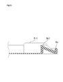
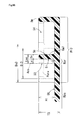
- Fig. 37 shows a state of the water absorbent sheet retaining mat M7 sectioned with a focus on the mat frame member Rm7 in Fig. 36 .
- Fig. 38 shows a state of the water absorbent sheet retaining mat M7 sectioned along with the slit center axis Acs of the retaining member Pr7 in Fig. 36 .
- Fig. 37 on the right side of the mat frame member Rm7, an end portion of the retaining member Pr7 located outside the mat frame member Rm7 (the mat member Pm7) is seen.
- a portion extending between the outer circumference and the two-dot chain line in a width We7 is the above described outer perimeter Pe7.
- the outer perimeter Pe7 is constructed to have an upper surface that flush with an upper surface of the peripheral wall Wr at a height T3.
- an upper surface of the outer perimeter Pe7 preferably slopes down from the center toward the outer perimeter of the mat member Pm7, as well as the width becomes greater from the top end toward the bottom end thereof.
- the tip of mat frame member Rm7 is formed in a curved shape.
- a thickness of mat frame member Rm7 is regard as Te (hereinafter referred to as a "mat frame member thickness Te"
- a side (the left side in Fig. 37 ) facing to the inside (the laying plane St) of the mat frame member Rm7 is regarded as an inner peripheral surface Si, a side (the right side in Fig.
- the water absorption region Rpa defined by the line connecting the slit center axes Acs corresponds to the absorption area Spa of the water absorbent sheet Sa1.
- the distance Lei corresponds to the width of the sheet brim standing region Rpr, and is referred to as a sheet brim standing region width Lei.
- the sheet brim standing region width Lei, the mat frame height H1, and the sheet brim width Lpr ( Fig. 2 ) of the sheet brim member Spr of the water absorbent sheet Sa1 there is a relationship expressed by the following equation (5) preferably.
- the cross section of the outer perimeter Pe7 is the biggest when cutting the retaining member Pr7 along a plane at a uniform angle with respect to both the neighboring mat frame members Rm7.
- the retaining member Pr7 is so constructed that the circular counter of the retaining member Pr1 is located within the circular contour of the retaining member Pr7 but closer to the center of the water absorbent sheet retaining mat M7.
- the mat frame member Rm7 With reference to Fig. 39 , described is an alternative embodiment of the mat frame member Rm7 with respect to the shape and the position to be arranged.
- First described is the shape.
- ⁇ 90°
- the outer peripheral surface So of the mat frame member Rm7b is positioned on the more outside (on the right side in Fig. 37 and Fig. 39 ) of the water absorbent sheet retaining mat M7, compared with the outer peripheral surface So of the mat frame member Rm7.
- the outer peripheral surface So of the mat frame member Rm7b is located on the more outside of the water absorbent sheet retaining mat M7 by a value f( ⁇ ) defined by ⁇ , compared with the example shown in Fig. 37 .
- the inner peripheral surface Si of the mat frame member Rm7c is positioned on the more inside (on the left side in Fig. 37 and Fig. 39 ) of the water absorbent sheet retaining mat M7, compared with the inner peripheral surface Si of the mat frame member Rm7.
- the inner peripheral surface Si of the mat frame member Rm7c is located on the more inside of the water absorbent sheet retaining mat M7 by a value f( ⁇ ) defined by ⁇ , compared with the example shown in Fig. 37 .
- a water absorbent sheet retaining mat M7a according to the present alternative embodiment has a construction similar to that of the water absorbent sheet retaining mat M1 shown in Fig. 3 , except that the retaining member Pr7 is replaced with the above described retaining member Pr1c ( Fig. 77 ).
- Fig. 40(a) shown is a perspective view of the water absorbent sheet retaining mat M7a focused on the retaining member Pr1c.
- Fig. 40(b) shown is a plan view of the water absorbent sheet retaining mat M7a of Fig. 40(a) looking down a top surface of the retaining member Pr1c.
- Fig. 40(a) shown is a perspective view of the water absorbent sheet retaining mat M7a focused on the retaining member Pr1c.
- Fig. 40(b) shown is a plan view of the water absorbent sheet retaining mat M7a of Fig. 40(a) looking down a top surface of the retaining member Pr1c.
- FIG. 40(c) shown is a side view of the water absorbent sheet retaining mat M7a focused on the retaining member Pr1c.
- Replacement of the retaining member Pr7 with the retaining member Pr1c enables the prevention of accidental removal of the water absorbent sheet Sa which is once installed as well as easy-to-pressing down the claw Psrud, as described in the above.
- a water absorbent sheet retaining mat M9 is constructed by modifying the above described water absorbent sheet retaining mat M7 ( Fig. 36 ) such that the retaining member Pr7 and the mat frame member Rm7 are replaced with a retaining member Pr9 and a mat frame member Rm9, respectively. Specifically, an outer perimeter Pe9 of the retaining member Pr9 and an outer peripheral surface Rse9 of the mat frame member Rm9 are integrally formed in the water absorbent sheet retaining mat M9.
- the mat frame member Rm9 is provided with the outer peripheral surface Rse9 ( Fig. 42 ) sloping from a top end of the outer peripheral surface So toward a plane extended from the sitting plane Sb of the mat member Pm7 as well as from the center toward an outer periphery of the mat member Pm7 in the mat frame member Rm7 ( Fig. 36 ).
- an upper surface of the outer perimeter Pe9 of the retaining member Pr9 slopes from the center of the mat member Pm7 toward the outer periphery thereof.
- the outer perimeter Pe9 is constructed to have the width becoming larger from the top end toward the bottom end thereof (We9t ⁇ We9b).
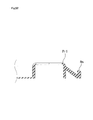
- Fig. 44 shown is a cross sectional view of an alternative embodiment of the mat frame member Rm9.
- the angle ⁇ could be a value within a range about from 80° till 85°, and the mat frame member Rm9a is formed in a shape sloping from the outer perimeter toward the center of the mat member Pm7.
- a water absorbent sheet retaining mat M10 is constructed by modifying the above described water absorbent sheet retaining mat M9 ( Fig. 41 ) according to the eighth embodiment such that the retaining member Pr9 and the mat frame member Rm9 are replaced with a retaining member Pr10 and a mat frame member Rm10, respectively.
- an outer perimeter Pe10 of the retaining member Pr10 and an outer peripheral surface Rse10 of the mat frame member Rm10 are integrally formed as in the above described water absorbent sheet retaining mat M9.
- the mat frame member Rm10 is provided with an opening O formed therein unlike the mat frame member Rm9 (water absorbent sheet retaining mat M9).
- the mat frame member Rm10 has a picture frame like shape in a planer view in the example shown in Fig. 45 .
- the retaining member Pr10 has a construction basically similar to that of the retaining member Pr9 ( Fig. 41 ). In short, the outer perimeter Pe10 of the retaining member Pr10 is constructed to have the width becoming larger from the top end toward the bottom end thereof.
- the mat frame member Rm10 has an outer peripheral member Rpe10 which extends from the center of the mat member Pm7 toward the outer perimeter in the outer peripheral surface thereof.
- the outer peripheral member Rpe10 has a first outer peripheral member Ripe10 and a second outer peripheral member Rope10.
- the first outer peripheral member Ripe10 and the second outer peripheral member Rope10 are integrally formed. As described later, the opening O is formed in the mat frame member Rm10.
- the first outer peripheral member Ripe10 extends from the outer peripheral surface of the mat frame member Rm10 toward the opposite side with respect to the center of the mat member Pm7 by the length Lipe10.
- An upper surface of the first outer peripheral member Ripe10 slopes from the top end of the outer peripheral surface of the mat frame member Rm10 toward a plane extending from the sitting plane Sb of the mat member Pm7.
- the second outer peripheral member Rope10 is integrally formed with the first outer peripheral member Ripe10, and also extends from the center of the mat member Pm7 towards the outer perimeter by a length Lope10.
- the second outer peripheral member Rope10 has a predetermined height t4 (not shown), and the height t4 is smaller than a height t3 (not shown) of the mat frame member Rm10.
- the openings O are formed in the mat frame member Rm10 located in the right and left sides, respectively.
- the opening O is formed in the mat frame member Rm10 in a position adjacent to the short side of the mat member Pm7. Since the opening O is provided for the convenience of the user's handling, the opening O can be formed in any size or any shape which satisfy the requirements.
- the angle ⁇ made by the mat frame member Rm10 with the laying plane St of the mat member Pm7 is an obtuse angle, and the inner peripheral surface of the mat frame member Rm10 is allowed to slope from the center of the mat member Pm7 toward the outer perimeter.
- the angle ⁇ made by the retaining member Pr10 with the laying plane St of the mat member Pm7 is an obtuse angle, and the inner peripheral surface of the retaining member Pr10 is allowed to slope from the center of the mat member Pm7 toward the outer perimeter.
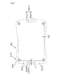
- a water absorbent sheet retaining mat M11 has a construction where the above described water absorbent sheet retaining mat M1 ( Fig. 3 ) of the first embodiment is applied with the above described mat frame member Rm7 ( Fig. 36 , Fig. 37 ) of the seventh embodiment.
- the mat frame member Rm7 integrally connects between the retaining members Pr1.
- An area between the mat frame member Rm and the mat frame member Rm7 is referred to as an "inter-perimeter region Rrr.”
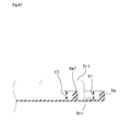
- Fig. 47 shows a state of the water absorbent sheet retaining mat M11 sectioned with a focus on the mat frame member Rm and the mat frame member Rm7 in Fig. 46 .
- Fig. 48 shows a state of the water absorbent sheet retaining mat M11 sectioned along with the slit center axis Acs ( Fig. 37 ) of the retaining member Pr1 in Fig. 46 .
- the inter-perimeter region Rrr is constructed by a flat surface.
- a height H7 of the mat frame member Rm7 equals to the height H1 of the mat frame member Rm.
- Fig. 49 described are alternative embodiments of the mat frame member Rm and the mat frame member Rm7.
- Fig. 49(a) it is allowed to construct the mat frame member Rm in a shape similar to that of the mat frame member Rm7a described with reference to Fig. 39(a) .
- Fig. 49(b) it is also allowed to construct both the mat frame member Rm and the mat frame member Rm7 in a shape similar to that of the mat frame member Rm7a.
- Fig. 49(c) it is allowed to construct the mat frame member Rm and the mat frame member Rm7 such that the height H7 of the mat frame member Rm7 is greater than the height H1 of the mat frame member Rm.
- the mat frame member Rm can be arranged so that a clearance between the mat frame member Rm and the mat frame member Rm7 almost equals to a clearance between the mat frame member Rm and the outer peripheral surface of the retaining member Pr1.
- the mat frame member Rm has corners each in which a corner member formed in a circular arc shape so as to shift outside from the mat frame member Rm discontinuously.
- a water absorbent sheet retaining mat M13 has a construction similar to that of the above described water absorbent sheet retaining mat M11 except that the inter-perimeter region Rrr is replaced with an inter-perimeter region Rrrs.
- Fig. 51 shows a state of the water absorbent sheet retaining mat M13 sectioned with a focus on the mat frame member Rm and the mat frame member Rm7 in Fig. 50 .
- Fig. 52 shows a state of the water absorbent sheet retaining mat M13 sectioned along with the slit center axis Acs of the retaining member Pr1 in Fig. 50 .
- the inter-perimeter region Rrrs is constructed by a sloping surface extending between the top end of the mat frame member Rm7 and the bottom end of the mat frame member Rm.
- Fig. 53 described are alternative embodiments of the mat frame member Rm and the mat frame member Rm7.
- Fig. 53(a) it is allowed to construct the mat frame member Rm so as to have a shape similar to that of the mat frame member Rm described with reference to Fig. 49(a) .
- Fig. 53(b) it is also allowed to construct the mat frame member Rm so as to have a shape similar to that of the mat frame member Rm illustrated in Fig. 53(a) as well as to construct such that the inner peripheral surface Si of the mat frame member Rm7 slants (80° ⁇ 85°) against the laying plane St.
- a water absorbent sheet retaining mat M14 has a construction similar to that of the above described water absorbent sheet retaining mat M11 except that the mat frame member Rm7 is replaced with a mat frame member Rm14. Although the above described mat frame member Rm7 is extending continuously, the mat frame member Rm14 according to the present embodiment is comprised of a plurality of mat frame members between each a gap G is formed.
- each the gap G is formed in a place almost parallel to the short side Lsm ( Fig. 3 ) of the mat member Pm1 in the mat frame member Rm14.
- Fig. 55 shows a state of the water absorbent sheet retaining mat M14 sectioned along with a line almost parallel to the short side Lsm ( Fig. 3 ) of the mat member Pm1 in the position of the mat frame member Rm14 in Fig. 54 . It is allowed that a height H14 of the mat frame member Rm14 is greater than the height of the retaining member Pr1.
- Fig. 56 shows a state of the water absorbent sheet retaining mat M14 sectioned along with a line almost parallel to the long side Llm ( Fig. 3 ) of the mat member Pm1 in the position of the mat frame member Rm14 in Fig. 54 .
- the mat frame member Rm14 is provided with a notch No at a position corresponding to almost the center thereof.
- the mat member Pm7 can be bent along a line connecting the notches No as shown in Fig. 57 and then the water absorbent sheet retaining mat M14, constructed as described in the above, can sit on even a place alongside a surface standing at a predetermined angle like a wall or a furniture with the bent portion contacting to the surface.
- the notches No absorb the deformations of the water absorbent sheet retaining mat M14 caused by being bent. It is allowed to construct such that the height H14 of the mat frame member Rm14 is greater than the height of the retaining member Pr1.
- a water absorbent sheet retaining mat M15 has a construction similar to that of the water absorbent sheet retaining mat M14 except that the mat frame member Rm14 is replaced with a mat frame member Rm15.
- Fig. 59 shows a state of the water absorbent sheet retaining mat M15 sectioned along with a line almost parallel to the short side Lsm ( Fig. 3 ) of the mat member Pm1 in the position of the mat frame member Rm15 in Fig. 58 .
- the mat frame member Rm15 is comprised of a plurality of mat frame members between each a gap G is formed.
- the end portions of the mat frame members neighbouring the gap G are formed to slope.
- a height H15 of the mat frame member Rm15 almost equals to the height t2 of the retaining member Pr1. However, it is allowed to construct such that the height H15 is greater than the height t2 and the top end of the mat frame member neighboring the retaining member Pr1 slopes toward the gap.
- a water absorbent sheet retaining mat M16 is similar to the above described water absorbent sheet retaining mat M7 ( Fig. 36 ) according to the seventh embodiment but the retaining member Pr7 is replaced with a retaining member Pr3c.
- the retaining member Pr3c is similar to the above described retaining member Pr3 ( Fig. 22 to Fig. 25 ) according to the third embodiment but a frame member Rpr3 is further provided.
- a plurality of the slit members S3 and S4 are integrally formed in the retaining member Pr3.
- Fig. 61 shows a state of the water absorbent sheet retaining mat M16 sectioned with a focus on the mat frame member Rm7 in Fig. 60 .
- Fig. 62 shows a state of the water absorbent sheet retaining mat M16 sectioned along with the slit center axis Acs of the retaining member Pr3c in Fig. 60 .
- the sheet brim standing region width Lei the distance between the center axis and the outer peripheral surface Leo, and the inner diameter Di3 and outer diameter Do3 of the slit member S3 of the retaining member Pr3c
- the retaining member Pr3a is similar to the retaining member Pr3 but the slit member S4 is replaced with a through hole Th.
- the through hole Th is formed in a direction almost perpendicular to the laying plane St.
- An outer peripheral surface Sop of the retaining member Pr3a is formed in a convex shape with a curved surface.
- it is allowed to provide a space in the bottom of the outer peripheral surface Sop formed in a convex shape with a curved surface.
- a water absorbent sheet retaining mat M16a is used in a state that two pieces of regular sized water absorbent sheets which are arranged side by side overlapping partially are retained on the laying plane St, similarly to the water absorbent sheet retaining mat M1a described with reference to Fig. 11 .
- the water absorbent sheet retaining mat M16a can be used in a state that one piece of wide sized water absorbent sheet is retained on the laying plane St otherwise.
- the water absorbent sheet retaining mat M16a has a construction similar to that of the water absorbent sheet retaining mat M16 except that the mat member Pm7 is replaced with a mat member Pm7a as well as a retaining member Pr1b is added. Note that no frame member is formed in the bottom of the retaining member Pr3.
- the retaining member Pr1b is described mainly.
- Two-dot chain lines connecting the center of the slit members S3 and S3 of the neighbouring retaining members Pr3 and Pr3 defines a rectangular area Rpa confined thereby.
- the retaining members Pr1b are provided such that the centers of the slit members S are located on positions corresponding to almost the center of lines connecting the centers of the slit members S3 and S3 of the neighbouring retaining members Pr3 and Pr3.
- the retaining member Pr1b is formed such that the top surface thereof is almost the same height as that of the top surface of the mat frame member Rm7.
- a water absorbent sheet retaining mat M16b has a construction similar to that of the above described water absorbent sheet retaining mat M16a except that the retaining member Pr1b is replaced with a retaining member Pr3b.
- the retaining member Pr3b is provided such that the center of the slit member S3 is located in a position corresponding about a center of a line connecting each center of the neighbouring retaining members Pr3 and Pr3.
- a water absorbent sheet retaining mat M17 has a construction similar to that of the above described water absorbent sheet retaining mat M11 ( Fig. 46 ) according to the tenth embodiment except that the retaining member Pr1 is replaced with the above described retaining member Pr3 according to the third embodiment.
- Fig. 68 shows a state of the water absorbent sheet retaining mat M17 sectioned with a focus on the mat frame member Rm and the mat frame member Rm7 in Fig. 67 .
- retaining member Pr3 is replaced with the above described retaining member Pr3a ( Fig. 63 , Fig. 64 ) in the water absorbent sheet retaining mat M17.
- a water absorbent sheet retaining mat M17a is constructed by adding the retaining member Pr1b described with reference to Fig. 65 to the water absorbent sheet retaining mat M17.
- a water absorbent sheet retaining mat M17b has a construction similar to that of the water absorbent sheet retaining mat M17a but the retaining member Pr1b is replaced by the retaining member Pr3b described with reference to Fig. 66 .
- the retaining member Pr3b is formed extending over the mat frame member Rm7 and the mat frame member Rm.
- a water absorbent sheet retaining mat M18 has a construction similar to that of the above described water absorbent sheet retaining mat M13 ( Fig. 50 ) according to the eleventh embodiment of the present invention except that the retaining member Pr1 is replaced with the above described the retaining member Pr3 according to the third embodiment.
- Fig. 72 shows a state of the water absorbent sheet retaining mat M18 sectioned with a focus on the mat frame member Rm and the mat frame member Rm7.
- a water absorbent sheet retaining mat M19 has a construction similar to that of the above described water absorbent sheet retaining mat M9 ( Fig. 41 ) according to the eighth embodiment except that the retaining member Pr9 is replaced with the above described retaining member Pr3 according to the third embodiment.
- Fig. 74 shows a state of the water absorbent sheet retaining mat M19 sectioned with a focus on the mat frame member Rm9 in Fig. 73 .
- a water absorbent sheet retaining mat M19a is constructed by adding the retaining member Pr1b described with reference to Fig. 65 to the water absorbent sheet retaining mat M19.
- a water absorbent sheet retaining mat M19b is constructed by replacing the retaining member Pr1b with the retaining member Pr3b described with reference to Fig. 66 in the water absorbent sheet retaining mat M19a.
- the present invention is applicable to a water absorbent sheet retaining mat which can retain a water absorbent sheet stably.
Landscapes
- Life Sciences & Earth Sciences (AREA)
- Environmental Sciences (AREA)
- Zoology (AREA)
- Animal Husbandry (AREA)
- Biodiversity & Conservation Biology (AREA)
- Housing For Livestock And Birds (AREA)
- Laminated Bodies (AREA)
Applications Claiming Priority (2)
| Application Number | Priority Date | Filing Date | Title |
|---|---|---|---|
| PCT/JP2012/052036 WO2013114544A1 (fr) | 2012-01-30 | 2012-01-30 | Tapis pour retenir une feuille absorbant l'eau |
| PCT/JP2012/062913 WO2013114641A1 (fr) | 2012-01-30 | 2012-05-21 | Mat de retenue d'une feuille hydro-absorbante |
Publications (2)
| Publication Number | Publication Date |
|---|---|
| EP2810552A1 true EP2810552A1 (fr) | 2014-12-10 |
| EP2810552A4 EP2810552A4 (fr) | 2015-07-01 |
Family
ID=48904626
Family Applications (1)
| Application Number | Title | Priority Date | Filing Date |
|---|---|---|---|
| EP12867329.0A Withdrawn EP2810552A4 (fr) | 2012-01-30 | 2012-05-21 | Mat de retenue d'une feuille hydro-absorbante |
Country Status (4)
| Country | Link |
|---|---|
| US (1) | US10299461B2 (fr) |
| EP (1) | EP2810552A4 (fr) |
| CN (1) | CN104080331B (fr) |
| WO (2) | WO2013114544A1 (fr) |
Families Citing this family (7)
| Publication number | Priority date | Publication date | Assignee | Title |
|---|---|---|---|---|
| US20150101538A1 (en) * | 2012-10-11 | 2015-04-16 | Teresa Murphy | Modular Rigid Small Animal Cage Liner |
| US11278143B2 (en) * | 2016-12-12 | 2022-03-22 | Sak Group Llc | Absorbent pad holder and containment system |
| US11771947B2 (en) * | 2020-03-03 | 2023-10-03 | Levigato, LLC | Folding athletics mat with magnetic assembly |
| USD975940S1 (en) * | 2020-12-02 | 2023-01-17 | Brian J P Grant | Pet urine pad |
| CN117279498B (zh) * | 2021-05-07 | 2026-02-06 | 四爪产品有限公司 | 提升的宠物废物收集训练垫 |
| US12239876B2 (en) * | 2021-05-16 | 2025-03-04 | James Smallwood | Folding mat for relieving sciatic and coccyx pressure when exercising and meditating |
| USD1068186S1 (en) * | 2024-11-20 | 2025-03-25 | Wellfine Silicone Products Co., Ltd. | Pet urine pad |
Family Cites Families (48)
| Publication number | Priority date | Publication date | Assignee | Title |
|---|---|---|---|---|
| US2052973A (en) * | 1935-10-04 | 1936-09-01 | Furtzaig Abraham | Holder for kneeling pads |
| US2492890A (en) * | 1947-02-28 | 1949-12-27 | Sameth Sigmund | Shoulder pad |
| US3099855A (en) * | 1962-02-01 | 1963-08-06 | Johnson & Johnson | Cleaning implement |
| US3237904A (en) * | 1963-05-21 | 1966-03-01 | Abruzese Michael | Beach blanket anchor |
| US3416495A (en) * | 1966-11-02 | 1968-12-17 | Wilson Henry Allen | Pet pan with disposable lining |
| US3516111A (en) * | 1967-12-22 | 1970-06-23 | Heyman Mfg Co | Universal bushing |
| US3537116A (en) * | 1968-09-26 | 1970-11-03 | Calvin L Kain | Versatile folding pad |
| US3785451A (en) * | 1972-08-04 | 1974-01-15 | Ghigo A | Flexible and fireproof automobile diaper |
| US4599754A (en) * | 1984-10-09 | 1986-07-15 | Mairs Iii Robert W | Combination wind screen and beach blanket apparatus |
| US5102316A (en) | 1986-08-22 | 1992-04-07 | Copeland Corporation | Non-orbiting scroll mounting arrangements for a scroll machine |
| US5092010A (en) * | 1991-02-20 | 1992-03-03 | Wong Wai S | Bedclothes |
| US5211133A (en) * | 1992-01-28 | 1993-05-18 | Foley James F | Litter saver device |
| JP2690049B2 (ja) | 1992-07-13 | 1997-12-10 | 国際電信電話株式会社 | 偏波分散測定方法及び装置 |
| JPH0748055Y2 (ja) * | 1992-10-15 | 1995-11-08 | ペパーレット株式会社 | 愛玩動物用トイレ |
| US5311837A (en) * | 1993-04-19 | 1994-05-17 | Mamer Boellstorff Leslie | Pet bed |
| US5567916A (en) * | 1993-06-11 | 1996-10-22 | Siecor Corporation | Grommet |
| US6199230B1 (en) * | 1997-08-11 | 2001-03-13 | Christina M. Parikh | Children's foldable portable indoor/outdoor play mat/corral |
| US5966757A (en) * | 1998-06-26 | 1999-10-19 | Sullivan; Donald W. | Stay put towel/blanket system |
| US6405394B1 (en) * | 1999-03-22 | 2002-06-18 | Frank S. Rosenberg | Method of changing a baby's diaper |
| JP3753581B2 (ja) * | 1999-05-20 | 2006-03-08 | 花王株式会社 | 吸収性物品 |
| JP3068906U (ja) * | 1999-11-11 | 2000-05-26 | 株式会社リッチェル | マット |
| EP1466522B1 (fr) * | 2000-01-14 | 2006-11-29 | Kao Corporation | Procédé de fabrication de matériau destiné à l'élimination d'excréments |
| DE10012998B4 (de) * | 2000-03-16 | 2005-10-27 | Wilhelm Schreiner | Nässeschutzmatte für Tiertransporter |
| US6450119B1 (en) * | 2001-02-12 | 2002-09-17 | Coastal Pet Products, Inc. | System for holding a pad |
| US6606757B2 (en) * | 2001-03-29 | 2003-08-19 | Quickie Manufacturing Corp. | Flexible dust mop |
| US6737150B2 (en) * | 2001-09-28 | 2004-05-18 | Everwear Professional Products, Inc. | Folding floor mat |
| JP4079648B2 (ja) * | 2002-02-04 | 2008-04-23 | アイリスオーヤマ株式会社 | ペット用トレー |
| US6550423B1 (en) * | 2002-04-01 | 2003-04-22 | The Bramton Company | Dog waste disposal pad holder |
| JP2007110929A (ja) | 2005-10-18 | 2007-05-10 | Keiko Takahashi | ペット用トイレマット |
| US8973530B2 (en) * | 2006-03-17 | 2015-03-10 | Eleanor Spreitzer | Cat litter box cleaning system |
| US7367621B1 (en) * | 2006-05-15 | 2008-05-06 | Han-Dressor Joannie U | Disposable shopping cart child seat liner |
| CN2927672Y (zh) * | 2006-07-03 | 2007-08-01 | 上海集升实业有限公司 | 用于母狗的宠物垫 |
| US7673584B2 (en) | 2007-01-31 | 2010-03-09 | Aley Thomas E | Vertical pet excrement collection device |
| CN101273710A (zh) * | 2007-03-28 | 2008-10-01 | 王妙玲 | 一种防渗宠物垫及其制造方法 |
| US8225748B2 (en) * | 2007-12-14 | 2012-07-24 | Robert Jordy Crawford | Potty pole |
| JP5185738B2 (ja) | 2008-08-29 | 2013-04-17 | ユニ・チャーム株式会社 | 愛玩動物用の排泄物処理シート |
| PL2383115T3 (pl) | 2008-12-29 | 2017-01-31 | Sumitomo Seika Chemicals Co. Ltd. | Kompozycja arkusza pochłaniającego wodę |
| US8113146B2 (en) * | 2009-05-27 | 2012-02-14 | Four Paws Products, Ltd. | Animal waste pad holder |
| CN201444803U (zh) * | 2009-07-09 | 2010-05-05 | 江苏中恒宠物用品有限公司 | 一种四层宠物尿垫 |
| CN201577376U (zh) * | 2009-12-09 | 2010-09-15 | 芜湖悠派生活用品有限公司 | 带有吸水木桨层的护理垫 |
| CN201798333U (zh) * | 2010-04-19 | 2011-04-20 | 上海艾可杰生物高分子材料有限公司 | 带有固定结构的水凝胶垫 |
| US20120000428A1 (en) * | 2010-07-01 | 2012-01-05 | Georgia-Pacific Wood Products Llc | Small animal bedding system |
| US20130014325A1 (en) * | 2011-07-11 | 2013-01-17 | Argento Virginia A | Ascetically and size customizable towel for the beach |
| US20140053785A1 (en) * | 2012-08-23 | 2014-02-27 | Absolutelynew, Inc. | Holder for Flexible Sheet Material |
| US20140068858A1 (en) * | 2012-09-12 | 2014-03-13 | David Wambeke | Fastenable exercise mat and towel assembly |
| US9723808B2 (en) * | 2013-02-08 | 2017-08-08 | Tarky Co., Ltd. | Water absorbent sheet retaining mat |
| JP6173769B2 (ja) * | 2013-05-17 | 2017-08-02 | ユニ・チャーム株式会社 | ペット用吸収性シート |
| US9776033B2 (en) * | 2014-08-26 | 2017-10-03 | Snap Mat Systems Inc. | Yoga mat assembly |
-
2012
- 2012-01-30 WO PCT/JP2012/052036 patent/WO2013114544A1/fr not_active Ceased
- 2012-05-21 WO PCT/JP2012/062913 patent/WO2013114641A1/fr not_active Ceased
- 2012-05-21 CN CN201280068415.1A patent/CN104080331B/zh active Active
- 2012-05-21 US US14/375,343 patent/US10299461B2/en not_active Expired - Fee Related
- 2012-05-21 EP EP12867329.0A patent/EP2810552A4/fr not_active Withdrawn
Also Published As
| Publication number | Publication date |
|---|---|
| US10299461B2 (en) | 2019-05-28 |
| CN104080331B (zh) | 2015-11-25 |
| EP2810552A4 (fr) | 2015-07-01 |
| US20150007777A1 (en) | 2015-01-08 |
| WO2013114641A1 (fr) | 2013-08-08 |
| WO2013114544A1 (fr) | 2013-08-08 |
| CN104080331A (zh) | 2014-10-01 |
Similar Documents
| Publication | Publication Date | Title |
|---|---|---|
| EP2810552A1 (fr) | Mat de retenue d'une feuille hydro-absorbante | |
| US9723808B2 (en) | Water absorbent sheet retaining mat | |
| KR970032729A (ko) | 청소용구 | |
| KR101364161B1 (ko) | 문어 양식장치 | |
| KR101306485B1 (ko) | 동물용 식기 거치장치 | |
| EP2010339A2 (fr) | Appareil permettant de maintenir les composants d'un biberon dans un lave-vaisselle | |
| KR20190003142U (ko) | 가금류 사육용 케이지 저판구조 | |
| JP2018171030A (ja) | トイレマットカバーおよびそれを有するペット用トイレ | |
| JP2011502914A (ja) | モジュールベルト用の交換可能な装着部材および装着部材保持具 | |
| KR200444185Y1 (ko) | 돈사의 바닥 보호판 | |
| JP3068906U (ja) | マット | |
| US9572472B2 (en) | Cleaning device for use with disposable cleaning elements | |
| CN219352680U (zh) | 一种扣合式猫砂垫 | |
| CN210328896U (zh) | 一种宠物垫 | |
| KR200441235Y1 (ko) | 연설구조를 단순화시킨 케이블 베어 | |
| KR890001918Y1 (ko) | 돈사용 개량 바닥판의 구조 | |
| JPWO2013114641A1 (ja) | 吸水シート保持マット | |
| EP3079462B1 (fr) | Auge longue | |
| JP2021090362A (ja) | 畜舎用すのこ | |
| JP5379180B2 (ja) | ペット用トイレ | |
| CN202843091U (zh) | 一种床罩固定装置 | |
| KR200244516Y1 (ko) | 양계장용 분리형 모이통 | |
| JP2024106280A (ja) | 小動物用排泄容器 | |
| KR200466220Y1 (ko) | 양돈장 임신 스톨의 주철 바닥재 구조 | |
| JPH036208Y2 (fr) |
Legal Events
| Date | Code | Title | Description |
|---|---|---|---|
| PUAI | Public reference made under article 153(3) epc to a published international application that has entered the european phase |
Free format text: ORIGINAL CODE: 0009012 |
|
| 17P | Request for examination filed |
Effective date: 20140827 |
|
| AK | Designated contracting states |
Kind code of ref document: A1 Designated state(s): AL AT BE BG CH CY CZ DE DK EE ES FI FR GB GR HR HU IE IS IT LI LT LU LV MC MK MT NL NO PL PT RO RS SE SI SK SM TR |
|
| AX | Request for extension of the european patent |
Extension state: BA ME |
|
| DAX | Request for extension of the european patent (deleted) | ||
| RA4 | Supplementary search report drawn up and despatched (corrected) |
Effective date: 20150602 |
|
| RIC1 | Information provided on ipc code assigned before grant |
Ipc: A01K 1/01 20060101AFI20150527BHEP |
|
| RIN1 | Information on inventor provided before grant (corrected) |
Inventor name: NAKATA, TSUYOSHI Inventor name: NONOGUCHI, SEIJI |
|
| 17Q | First examination report despatched |
Effective date: 20171030 |
|
| STAA | Information on the status of an ep patent application or granted ep patent |
Free format text: STATUS: THE APPLICATION IS DEEMED TO BE WITHDRAWN |
|
| 18D | Application deemed to be withdrawn |
Effective date: 20180510 |