EP2810685A1 - Connecteur - Google Patents
Connecteur Download PDFInfo
- Publication number
- EP2810685A1 EP2810685A1 EP20130743848 EP13743848A EP2810685A1 EP 2810685 A1 EP2810685 A1 EP 2810685A1 EP 20130743848 EP20130743848 EP 20130743848 EP 13743848 A EP13743848 A EP 13743848A EP 2810685 A1 EP2810685 A1 EP 2810685A1
- Authority
- EP
- European Patent Office
- Prior art keywords
- male connector
- valve
- connector
- slit
- housing
- Prior art date
- Legal status (The legal status is an assumption and is not a legal conclusion. Google has not performed a legal analysis and makes no representation as to the accuracy of the status listed.)
- Granted
Links
Images



Classifications
-
- A—HUMAN NECESSITIES
- A61—MEDICAL OR VETERINARY SCIENCE; HYGIENE
- A61M—DEVICES FOR INTRODUCING MEDIA INTO, OR ONTO, THE BODY; DEVICES FOR TRANSDUCING BODY MEDIA OR FOR TAKING MEDIA FROM THE BODY; DEVICES FOR PRODUCING OR ENDING SLEEP OR STUPOR
- A61M39/00—Tubes, tube connectors, tube couplings, valves, access sites or the like, specially adapted for medical use
- A61M39/10—Tube connectors; Tube couplings
-
- A—HUMAN NECESSITIES
- A61—MEDICAL OR VETERINARY SCIENCE; HYGIENE
- A61M—DEVICES FOR INTRODUCING MEDIA INTO, OR ONTO, THE BODY; DEVICES FOR TRANSDUCING BODY MEDIA OR FOR TAKING MEDIA FROM THE BODY; DEVICES FOR PRODUCING OR ENDING SLEEP OR STUPOR
- A61M39/00—Tubes, tube connectors, tube couplings, valves, access sites or the like, specially adapted for medical use
- A61M39/22—Valves or arrangement of valves
- A61M39/26—Valves closing automatically on disconnecting the line and opening on reconnection thereof
-
- A—HUMAN NECESSITIES
- A61—MEDICAL OR VETERINARY SCIENCE; HYGIENE
- A61M—DEVICES FOR INTRODUCING MEDIA INTO, OR ONTO, THE BODY; DEVICES FOR TRANSDUCING BODY MEDIA OR FOR TAKING MEDIA FROM THE BODY; DEVICES FOR PRODUCING OR ENDING SLEEP OR STUPOR
- A61M39/00—Tubes, tube connectors, tube couplings, valves, access sites or the like, specially adapted for medical use
- A61M39/10—Tube connectors; Tube couplings
- A61M2039/1072—Tube connectors; Tube couplings with a septum present in the connector
-
- A—HUMAN NECESSITIES
- A61—MEDICAL OR VETERINARY SCIENCE; HYGIENE
- A61M—DEVICES FOR INTRODUCING MEDIA INTO, OR ONTO, THE BODY; DEVICES FOR TRANSDUCING BODY MEDIA OR FOR TAKING MEDIA FROM THE BODY; DEVICES FOR PRODUCING OR ENDING SLEEP OR STUPOR
- A61M39/00—Tubes, tube connectors, tube couplings, valves, access sites or the like, specially adapted for medical use
- A61M39/10—Tube connectors; Tube couplings
- A61M2039/1083—Tube connectors; Tube couplings having a plurality of female connectors, e.g. Luer connectors
-
- A—HUMAN NECESSITIES
- A61—MEDICAL OR VETERINARY SCIENCE; HYGIENE
- A61M—DEVICES FOR INTRODUCING MEDIA INTO, OR ONTO, THE BODY; DEVICES FOR TRANSDUCING BODY MEDIA OR FOR TAKING MEDIA FROM THE BODY; DEVICES FOR PRODUCING OR ENDING SLEEP OR STUPOR
- A61M39/00—Tubes, tube connectors, tube couplings, valves, access sites or the like, specially adapted for medical use
- A61M39/10—Tube connectors; Tube couplings
- A61M2039/1088—Tube connectors; Tube couplings having a plurality of male connectors, e.g. Luer connectors
-
- A—HUMAN NECESSITIES
- A61—MEDICAL OR VETERINARY SCIENCE; HYGIENE
- A61M—DEVICES FOR INTRODUCING MEDIA INTO, OR ONTO, THE BODY; DEVICES FOR TRANSDUCING BODY MEDIA OR FOR TAKING MEDIA FROM THE BODY; DEVICES FOR PRODUCING OR ENDING SLEEP OR STUPOR
- A61M2205/00—General characteristics of the apparatus
- A61M2205/02—General characteristics of the apparatus characterised by a particular materials
- A61M2205/0216—Materials providing elastic properties, e.g. for facilitating deformation and avoid breaking
-
- A—HUMAN NECESSITIES
- A61—MEDICAL OR VETERINARY SCIENCE; HYGIENE
- A61M—DEVICES FOR INTRODUCING MEDIA INTO, OR ONTO, THE BODY; DEVICES FOR TRANSDUCING BODY MEDIA OR FOR TAKING MEDIA FROM THE BODY; DEVICES FOR PRODUCING OR ENDING SLEEP OR STUPOR
- A61M39/00—Tubes, tube connectors, tube couplings, valves, access sites or the like, specially adapted for medical use
- A61M39/02—Access sites
- A61M39/04—Access sites having pierceable self-sealing members
- A61M39/045—Access sites having pierceable self-sealing members pre-slit to be pierced by blunt instrument
-
- A—HUMAN NECESSITIES
- A61—MEDICAL OR VETERINARY SCIENCE; HYGIENE
- A61M—DEVICES FOR INTRODUCING MEDIA INTO, OR ONTO, THE BODY; DEVICES FOR TRANSDUCING BODY MEDIA OR FOR TAKING MEDIA FROM THE BODY; DEVICES FOR PRODUCING OR ENDING SLEEP OR STUPOR
- A61M39/00—Tubes, tube connectors, tube couplings, valves, access sites or the like, specially adapted for medical use
- A61M39/10—Tube connectors; Tube couplings
- A61M39/105—Multi-channel connectors or couplings, e.g. for connecting multi-lumen tubes
-
- Y—GENERAL TAGGING OF NEW TECHNOLOGICAL DEVELOPMENTS; GENERAL TAGGING OF CROSS-SECTIONAL TECHNOLOGIES SPANNING OVER SEVERAL SECTIONS OF THE IPC; TECHNICAL SUBJECTS COVERED BY FORMER USPC CROSS-REFERENCE ART COLLECTIONS [XRACs] AND DIGESTS
- Y10—TECHNICAL SUBJECTS COVERED BY FORMER USPC
- Y10T—TECHNICAL SUBJECTS COVERED BY FORMER US CLASSIFICATION
- Y10T137/00—Fluid handling
- Y10T137/0318—Processes
- Y10T137/0402—Cleaning, repairing, or assembling
- Y10T137/0491—Valve or valve element assembling, disassembling, or replacing
-
- Y—GENERAL TAGGING OF NEW TECHNOLOGICAL DEVELOPMENTS; GENERAL TAGGING OF CROSS-SECTIONAL TECHNOLOGIES SPANNING OVER SEVERAL SECTIONS OF THE IPC; TECHNICAL SUBJECTS COVERED BY FORMER USPC CROSS-REFERENCE ART COLLECTIONS [XRACs] AND DIGESTS
- Y10—TECHNICAL SUBJECTS COVERED BY FORMER USPC
- Y10T—TECHNICAL SUBJECTS COVERED BY FORMER US CLASSIFICATION
- Y10T137/00—Fluid handling
- Y10T137/9029—With coupling
Definitions
- the present invention relates to a connector capable of liquid-tightly connecting a male connector of various medical instruments, infusion containers or the like, for example.
- the liquid is infused into the body by using a medical tube.
- a connector capable of liquid-tightly connecting a male connector of a syringe, a lure taper member or the like and a medical tube to each other is used.
- a male connector of a syringe, a lure taper member or the like may be referred to as a male lure, and a connector to be connected to the male lure may be referred to as a female lure.
- Patent Literature 1 An example of such connector capable of connecting a male connector is disclosed in Patent Literature 1.
- the connector disclosed in Patent Literature 1 includes a disk-like valve which has an insertion hole formed on the central part thereof, a base which supports the lower part of the peripheral edge of the valve excepting the central part of a back surface of the valve, and a cover which fixedly supports the valve by covering at least the upper part of the peripheral edge of the valve excepting the central part of a front surface of the valve.
- a male connector is retained in a mixed injection port by the edge end of the cover which forms a fitting hole with the male connector penetrating the valve. In this manner, holding/fixing of the male connector in the mixed injection port and communication between flow paths of the male connector and the mixed injection port are performed.
- Patent Literature 1 Japanese Patent Publication No. 3389983
- the tip end of the male connector enters the flow path. Therefore, the tip end of the male connector comes into contact with liquid inside the flow path. Thus, if the tip end of the male connector has bacteria adhering thereon, the liquid inside the flow path will be disadvantageously contaminated.
- a connector includes: a housing having a flow path through which liquid passes, and a male connector connecting portion having a substantially circular tube hole communicating with the flow path; and a valve formed of an elastic material and adapted to block the male connector connecting portion of the housing.
- the valve is formed in a substantially columnar shape, and includes: a top surface exposed from the male connector connecting portion; a bottom surface opposite to the top surface; and a slit opened at least on the top surface or the bottom surface.
- the housing includes a stopping portion which is adapted to be engaged with a tip end of the male connector to define an insertion length of the male connector.
- the top surface of the valve is pressed by the male connector.
- the valve thereby elastically deforms to form an opening communicating with the flow path.
- the male connector communicates with the flow path of the housing though the opening formed by the valve.
- the stopping portion of the housing defines the insertion length of the male connector, it is possible to prevent the male connector from penetrating the valve. Therefore, it is possible to reliably prevent the male connector from entering the flow path. Further, since the valve is not caused to deform more than necessary, it is possible to suppress or prevent the slit of the valve from being torn, and thereby maintain the air-tightness of the valve.
- the valve can be sufficiently opened without causing the tip end of the male connector to penetrate the valve. Therefore, it is possible to reliably prevent the male connector from entering the flow path, and prevent the slit of the valve from being torn.
- Fig. 1 is a cross-sectional view illustrating the connector according to the first embodiment.
- Fig. 2 is a plan view of a housing main body of the connector according to the first embodiment.
- Fig. 3 is a cross-sectional view taken along line A-A of Fig. 1 .
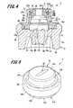
- Fig. 4 is a cross-sectional view taken along line B-B of Fig. 1 .
- a connector 1 includes a housing 2, and a valve 3 fixed to the housing 2.
- Examples of the material of the housing 2 include polyolefins such as polyethylene, polypropylene, ethylenepropylene copolymers, and ethylene-vinyl acetate copolymers (EVA) and the like, polyvinyl chloride, polyvinylidene chloride, polystyrene, polyamide, polyimide, polyamideimide, polycarbonate, poly(4-methylpentene-1), ionomers, acrylic resins, polymethyl methacrylate, acrylonitrile-butadienestyrene copolymer (ABS resin), acrylic-styrene copolymers (AS resins), butadiene styrene copolymers, polyesters such as polyethylene terephthalate (PET), polybutylene terephthalate (PBT), polycyclohexane terephthalate (PCT), polyether, polyether ketone (PEK), polyether ether ketone (PEEK), polyether imide, polyacetal (
- the housing 2 includes a housing main body 5, and a male connector connecting portion 6 joined to the housing main body 5.
- the housing main body 5 is a substantially columnar hollow casing, and has an upper surface 5a, a lower surface 5b, and an outer peripheral surface 5c, wherein the upper surface 5a is one end in the axial direction, and the lower surface 5b is the other end.
- a first tube connecting port 11 and a second tube connecting port 12 are arranged on the outer peripheral surface 5c of the housing main body 5.
- the tube connecting ports 11, 12 are each formed in a cylindrical shape protruding from the outer peripheral surface 5c of the housing main body 5. Both of the axis of the first tube connecting port 11 and the axis of the second tube connecting port 12 coincide with the radial direction of the housing main body 5.
- a step portion 14 having a substantially circular shape is formed on the upper surface 5a of the housing main body 5.
- the male connector connecting portion 6 is fitted to the step portion 14.
- a flow path recess 15 is formed on the center of the step portion 14.
- the flow path recess 15 has a substantially circular planar shape, and communicates with the first tube connecting port 11 and the second tube connecting port 12. In other words, the flow path recess 15 forms a flow path 13 inside the housing main body 5.
- Protruding walls 16, 17 are formed on an inner wall surface of the flow path recess 15.
- the protruding walls 16, 17 face each other in a direction perpendicular to the direction in which the first tube connecting port 11 and the second tube connecting port 12 face each other.
- a connecting wall 18 is provided between the protruding wall 16 and the protruding wall 17.
- the connecting wall 18 is integrally formed with the protruding wall 16 and the protruding wall 17. Therefore, liquid such as a medical solution flowing from the first tube connecting port 11 flows over the connecting wall 18, and flows into the second tube connecting port 12. On the other hand, liquid such as a medical solution flowing from the second tube connecting port 12 flows over the connecting wall 18, and flows into the first tube connecting port 11.
- An upper surface 16a of the protruding wall 16 and an upper surface 17a of the protruding wall 17 are located on the same plane.
- a stopping portion 19 is formed on the upper surface 16a of the protruding wall 16.
- a stopping portion 20 is formed on the upper surface 17a of the protruding wall 17.
- These stopping portions 19, 20 define an insertion length of a male connector 100 (described below, see Fig. 8 ).
- the stopping portions 19, 20 face each other in the direction perpendicular to the direction in which the first tube connecting port 11 and the second tube connecting port 12 face each other as with the protruding walls 16, 17.
- the stopping portions 19, 20 are each formed in a projection shape protruding in an upper direction.
- the upper direction is opposite to an insertion direction of the male connector 100 with respect to the connector 1.
- the stopping portions 19, 20 are each formed in a tapered shape whose diameter decreases toward the end thereof (see Fig. 4 ).
- the male connector connecting portion 6 communicates with the flow path 13 of the housing 2.
- the male connector connecting portion 6 includes a first member 21 which is joined to the housing main body 5 and a second member 22 which is joined to the first member 21.
- the first member 21 forms a base end of the male connector connecting portion 6.
- the first member 21 includes an inner tubular portion 24 and a flange portion 25.
- the inner tubular portion 24 is fitted into an outer tubular portion 28 (described below) of the second member 22.
- a tube hole of the inner tubular portion 24 is formed in a circular shape.
- a fitting recess 24a for fitting thereinto a fixing portion 32 (described below) of the valve 3 is formed on one end in the axial direction of the inner tubular portion 24.
- a tapered surface 24b is formed on an inner surface of the inner tubular portion 24, the inner surface forming the circular tube hole. The tapered surface 24b allows the diameter of the tube hole to increase toward the other end in the axial direction of the inner tubular portion 24.
- the flange portion 25 is continuous with the other end in the axial direction of the inner tubular portion 24, and is formed in a ring-like shape protruding outward in the radial direction of the inner tubular portion 24.
- the outer diameter of the flange portion 25 is substantially equal to the diameter of the step portion 14 of the housing main body 5.
- the flange portion 25 is fitted to the step portion 14 so as to be joined to the housing main body 5.
- the flange portion 25 may also be joined to the housing main body 5 by other fixing methods such as adhesive, fusion, a fixing screw, and the like.
- An engagement groove 25a with which an engagement projection 29a (described below) of the second member 22 is engaged is formed on an upper surface of the flange portion 25.
- the second member 22 forms a tip end of the male connector connecting portion 6.
- the second member 22 includes a connector fitting portion 27 into which the male connector 100 (see Fig. 8 ) is fitted, the outer tubular portion 28 which is continuous with the connector fitting portion 27, and an engagement portion 29 which is continuous with the outer tubular portion 28.
- the connector fitting portion 27 is formed in a substantially cylindrical shape, and has a tube hole 27a.
- a tapered surface 27b is formed on an inner surface of the connector fitting portion 27.
- the tapered surface 27b allows the diameter of the tube hole 27a to increase toward one end in the axial direction of the connector fitting portion 27. By forming the tapered surface 27b, it is possible to easily insert the male connector 100 into the connector fitting portion 27.
- a recess 27c for fitting thereinto the fixing portion 32 of the valve 3 is formed on the other end in the axial direction of the connector fitting portion 27.
- the male connector connecting portion 6 fixes the valve 3 by sandwiching the fixing portion 32 of the valve 3 between the inner tubular portion 24 of the first member 21 and the connector fitting portion 27 of the second member 22.
- the outer tubular portion 28 is continuous with the other end in the axial direction of the connector fitting portion 27, and is formed in a cylindrical shape whose inner diameter is greater than the inner diameter of the connector fitting portion 27.
- the inner diameter of the outer tubular portion 28 is substantially equal to the outer diameter of the inner tubular portion 24 of the first member 21.
- the outer tubular portion 28 is fitted to an outer peripheral surface of the inner tubular portion 24 of the first member 21.
- the outer tubular portion 28 may also be fixed to the inner tubular portion 24 of the first member 21 by other fixing methods such as adhesive, fusion, a fixing screw, and the like.
- the outer diameter of the outer tubular portion 28 is substantially equal to the outer diameter of the connector fitting portion 27. Further, a screw portion 27d is formed on outer peripheral surfaces of the connector fitting portion 27 and the outer tubular portion 28. The screw portion 27d is adapted to be screwed with a lock portion (so-called "lure lock", which is not illustrated) formed around the male connector with a predetermined distance therebetween.
- a lock portion so-called "lure lock", which is not illustrated
- the engagement portion 29 is continuous with the tip end in the axial direction of the outer tubular portion 28, and protrudes outward in the radial direction of the outer tubular portion 28.
- the engagement projection 29a is formed on a lower surface of the engagement portion 29.
- the engagement projection 29a is engaged with the engagement groove 25a formed in the first member 21. Further, the engagement portion 29 is fitted into a fitting recess 7 of the housing main body 5 so as to be joined to the housing main body 5.
- the engagement portion 29 may also be fixed to the first member 21 and the housing main body 5 by other fixing methods such as adhesive, fusion, a fixing screw, and the like.
- the diameter X of the tube hole 27a of the connector fitting portion 27 is determined according to the size of an upper portion 31A of a deformable portion 31 (described below, see Fig. 5 ) of the valve 3.
- the diameter X of the tube hole 27a will be described in more detail below when discussing the dimensions of the valve 3. Further, it is preferred that the distance h between the lower peripheral edge of the tapered surface 27b and the upper surfaces 16a, 17a of the protruding walls 16, 17 be within the range of 5 to 15 mm.
- the diameter ⁇ of the tube hole of the inner tubular portion 24 is determined according to the size of a lower portion 31B of the deformable portion 31 (described below, see Fig. 5 ) of the valve 3, and is preferably equal to or larger than 4 mm.
- the tube hole of the inner tubular portion 24 is a space necessary for the valve 3 to elastically deform (described below).
- the diameter ⁇ of the inner tubular portion 24 may be at least partially equal to or larger than 4 mm.
- the diameter of the tube hole of the inner tubular portion 24 on the side of the connector fitting portion 27 may be equal to or larger than 4 mm.
- valve 3 will be described with reference to Figs 5 to 7 .
- Fig. 5 is a perspective view of the valve 3.
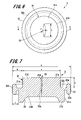
- Fig. 6 is a plan view of the valve.
- Fig. 7 is a cross-sectional view taken along line C-C of Fig. 6 .
- the valve 3 is molded using a metal mold (not illustrated), and formed to be elastically deformable.
- the material of the valve 3 include various kinds of rubber such as natural rubber, isoprene rubber, butadiene rubber, styrene-butadiene rubber, nitrile rubber, chloroprene rubber, butyl rubber, acrylic rubber, ethylenepropylene rubber, hydrin rubber, urethane rubber, silicone rubber, and fluorocarbon rubber, various kinds of thermoplastic elastomers such as a styrene-based elastomer, a polyolefine-based elastomer, a polyvinyl chloride-based elastomer, a polyurethane-based elastomer, a polyester-based elastomer, a polyamide-based elastomer, a polybutadine-based elastomer, and a fluorocarbon rubber-based elastomer.
- the material of the valve 3 also include
- the hardness of the valve 3 is preferably within the range of 20° to 60° (hardness A). Accordingly, since moderate elastic force of the valve 3 can be ensured, it is possible to allow the valve 3 to elastically deform (described below).
- the valve 3 includes the deformable portion 31 where a slit 33 is formed, and the fixing portion 32 which is continuous with the deformable portion 31.
- the deformable portion 31 is formed in a shape in which two columns having the same axis but different diameters are continuous with each other in the axial direction. Specifically, the deformable portion 31 has the upper portion 31A as an upper column and the lower portion 31B which is a column whose diameter is larger than the diameter of the upper portion 31A. The upper portion 31A forms a top surface 31a of the deformable portion 31. Further, the lower portion 31B forms a bottom surface 31b of the deformable portion 31.
- the fixing portion 32 is continuous with an outer peripheral surface 31c of the lower portion 31B.
- the lower portion 31B is formed in a column whose diameter is larger than the diameter of the upper portion 31A.
- the lower portion of the deformable portion according to the present invention may also be formed in a column whose diameter is smaller than the diameter of the upper portion, or a column whose diameter is equal to the diameter of the upper portion.
- the upper portion 31A of the deformable portion 31 is inserted into the tube hole 27a of the connector fitting portion 27 of the housing 2.
- the outer diameter of the upper portion 31A is larger than the diameter of the tube hole 27a of the connector fitting portion 27. Therefore, when the upper portion 31A of the deformable portion 31 is inserted into the tube hole 27a of the connector fitting portion 27, the upper portion 31A is compressed by the connector fitting portion 27 (the male connector connecting portion 6).
- the top surface 31a is a flat surface perpendicular to the axial direction of the deformable portion 31, and is exposed from the connector fitting portion 27 (the male connector connecting portion 6).
- the lower portion 31B of the deformable portion 31 is inserted into the tube hole of the inner tubular portion 24 of the housing 2.
- the outer diameter of the lower portion 31B of the deformable portion 31 is larger than the inner diameter of the inner tubular portion 24. Therefore, when the lower portion 31B of the deformable portion 31 is inserted into the tube hole of the inner tubular portion 24, the lower portion 31B is compressed by the inner tubular portion 24.
- a recess 34 which is curved to be recessed toward the top surface 31a, is formed on the bottom surface 31b of the deformable portion 31 (see Fig. 4 ). By providing the recess 34, the thickness of the valve 3 can be reduced. As a result, it is possible to easily deform the valve 3 when connecting the male connector 100 thereto.
- the slit 33 is opened on the top surface 31a of the deformable portion 31.
- the slit 33 is formed in a linear shape extending in the radial direction of the deformable portion 31, and has a predetermined width.
- the slit 33 is formed by a projection for slit formed in the mold (not illustrated).
- both ends in the longitudinal direction of the slit 33 are each formed in an arc shape. Accordingly, when the valve 3 is pressed by the male connector 100 (see Fig. 5 ) and thereby elastically deforms, both ends of the slit 33 are less likely to be torn. As a result, it is possible to improve the durability of the valve 3.
- both ends of the slit cannot be formed in an arc shape. Therefore, when the valve is pressed by a male connector and thereby elastically deforms, stress is concentrated on two points, namely, the both ends of the slits. As a result, both ends of the slit are likely to be torn.
- the length e in the longitudinal direction of the slit 33 is preferably within the range of 1 to 4 mm. If the length e of the slit 33 is too short, the openability of the valve 3 while elastically deforming will become worse. On the other hand, if the length e of the slit 33 is too long, the male connector 100 (see Fig. 8 ) will disadvantageously enter the slit 33.
- the width f which is the length in the short-length direction of the slit 33 is preferably within the range of 0.1 to 0.6 mm when taking into consideration that the slit 33 is closed when the valve 3 is compressed by the male connector connecting portion 6.
- the slit 33 has a tapered portion 33a whose opening becomes narrower toward the end thereof. Further, an end of the slit 33, the end being located on the opposite side of the top surface 31a, does not reach the recess 34 and is located within the deformable portion 31. In other words, a slight distance (0.01 to 1.0 mm, for example) is ensured between the end of the slit 33 located on the opposite side of the top surface 31a and the recess 34, and the slit 33 therefore does not communicate with the flow path 13 (see Fig. 4 ) of the housing 2.
- the top surface 31a of the valve 3 deforms to rotate with respect to the axis of the deformable portion 31, so as to form an opening 38 (see Fig. 8 ) which communicates with the flow path 13.
- the fixing portion 32 is continuous with the outer peripheral surface 31c of the lower portion 31B of the deformable portion 31, and protrudes outward in the radial direction of the deformable portion 31.
- the fixing portion 32 has an upper fixing piece 32a and a lower fixing piece 32b each of which protrudes in the axial direction of the deformable portion 31, and a flat surface 32c which is continuous with the outer peripheral surface of the deformable portion 31.
- the upper fixing piece 32a and the lower fixing piece 32b are each formed in a ring-like shape that is concentric with the deformable portion 31.
- the upper fixing piece 32a is fitted into the recess 27c of the connector fitting portion 27, and the lower fixing piece 32b is fitted into the fitting recess 24a of the inner tubular portion 24 of the housing 2 (see Fig. 4 ).
- the diameter a of the upper portion 31A of the deformable portion 31 is preferably within the range of 3 to 5 mm. If the diameter a is smaller than 3 mm, the diameter a will be smaller than the inner diameter of the male connector 100 (see Fig. 8 ) and the upper portion 31A of the deformable portion 31 may enter the male connector 100. If the upper portion 31A of the deformable portion 31 enters the male connector 100, the valve 3 will not elastically deform to open the slit 33.
- the distance between an outer peripheral surface 31e of the upper portion 31A of the deformable portion 31 and an outer peripheral surface 32d of the fixing portion 32 is defined as “distance b”
- the distance between the outer peripheral surface 31c of the lower portion 31B of the deformable portion 31 and the outer peripheral surface 32d of the fixing portion 32 is defined as “distance c”.
- the distance between the top surface 31a of the deformable portion 31 and the flat surface 32c of the fixing portion 32 is defined as "distance d”.
- the distances c and d are equal to or larger than 0.5 mm.
- the distance b is preferably within the range of 0.5 to 2.0 mm.
- the diameter of the upper portion 31A and the diameter of the lower portion 31B in the deformable portion 31 are equal to each other.
- the outer diameter L of the fixing portion 32 is preferably within the range of 5 to 7 mm. If the outer diameter L is too large, the outer diameter of the housing 2 also has to be set large. In this case, the screw portion 27d of the connector fitting portion 27 may not have a size that corresponds to the lock portion (the lure lock) of a male connector. On the other hand, if the outer diameter L is too small, the openability of the valve 3 while elastically deforming will become worse. Further, since the deformation amount of the valve 3 in the axial direction has to be made larger, the fixing property of the valve 3 with respect to the housing 2 will become worse.
- the diameter A of the upper portion 31A of the deformable portion 31 is set to approximately 4.1 mm, and the diameter of the lower portion 31B of the deformable portion 31 is set to approximately 5.1 mm. Further, the length in the axial direction of the deformable portion 31 is set to 3 mm, and the depth of the recess 34 on the bottom surface 31b is set to approximately 0.7 mm. As a result, the length in the axial direction of the central part of the deformable portion 31 is approximately 2.3 mm.
- the thickness of the central part of the deformable portion 31 is preferably equal to or less than 4.0 mm.
- the outer diameter L of the fixing portion 32 is set to approximately 6.2 mm, and the thickness of the fixing portion 32 is set to approximately 0.7 mm.
- the compressibility of the fixing portion 32 is preferably equal to or higher than 50%.
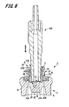
- Fig. 8 is a cross-sectional view illustrating a state in which the male connector 100 is connected to the connector 1.
- the male connector 100 is a portion or an instrument connected to the male connector connecting portion 6 of the connector 1.
- Examples of the male connector 100 include a part of a syringe (an injection device) to be connected by a needle tube, and a tubular instrument (such as a lure taper member and a sheath).
- the tip end of the male connector 100 is caused to face the male connector connecting portion 6 of the connector 1. Since the diameter of the male connector 100 continuously decreases toward the tip end thereof, the male connector 100 is liquid-tightly fitted to the connector fitting portion 27 of the male connector connecting portion 6.
- the tip end of the male connector 100 is inserted into the tube hole 27a of the connector fitting portion 27 to thereby press the top surface 31a of the deformable portion 31 of the valve 3 by the tip end of the male connector 100.
- the deformable portion 31 of the valve 3 elastically deforms downward. Accordingly, the upper portion 31A is displaced so as to sink into the lower portion 31B. Further, the lower portion 31B is displaced toward the flow path 13 while elastically deforming.
- the top surface 31a of the valve 3 abuts the tip end of the male connector 100. Further, the upper portion 31A of the deformable portion 31 sinks into the lower portion 31B, and the lower portion 31B is thereby displaced toward the flow path 13. As a result, the part of the slit 33 between the tip end of the slit 33 and the recess 34 (see Fig. 7 ) is torn, so that the slit 33 communicates with the flow path 13. In other words, the slit 33 extends in the depth direction thereof to penetrate the deformable portion 31.
- the tip end of the male connector 100 is further inserted into the tube hole 27a of the connector fitting portion 27. Accordingly, as illustrated in Fig. 8 , the tip end face of the male connector 100 comes to abut the stopping portions 19, 20, and the insertion length of the male connector 100 with respect to the connector 1 is thereby defined. At this time, the peripheral surface of a part of the male connector 100 from the tip end toward the base end is liquid-tightly fitted to the connector fitting portion 27.
- a lock portion (lure lock) is not provided. Therefore, the male connector 100 may penetrate the valve 3 if the stopping portion 19, 20 are not provided. Therefore, it is extremely effective to provide the stopping portions 19, 20.
- the stopping portions 19, 20 are each formed in a projection shape protruding upward, even when the male connector 100 abuts the stopping portions 19, 20, the flow path 13 is formed between the male connector 100 and the connecting wall 18. Therefore, even when the male connector 100 is in connection with the connector 1, liquid such as a medical solution flowing from the first tube connecting port 11 can flow over the connecting wall 18, and flow into the second tube connecting port 12.
- the provision of the stopping portions 19, 20 is effective also when using a male connector having a lock portion (lure lock).
- the deformable portion 31 of the valve 3 deforms by being pressed by the male connector 100 and thereby arranged around the stopping portions 19, 20. Specifically, the surface of the recess 34 of the deformable portion 31 of the valve 3 is pressingly expanded toward the tapered surface 24b of the inner tubular portion 24 of the housing 2.
- the inner surface 31d of the valve 3 deforms to radially rotate with respect to the axis so as to face the flow path 13 of the housing 2, while the bottom surface 31b warps toward the lateral side of the valve 3.
- the top surface 31a of the valve 3 is displaced so as to form a peripheral surface that surrounds the axis, so that the opening 38 which communicates with the flow path 13 of the housing 2 is formed.
- the tip end face and a part of the outer peripheral surface of the male connector 100 are in liquid-tight contact with the elastically deformed deformable portion 31. Therefore, the liquid-tightness between the connector 1 and the male connector 100 can be reliably ensured.
- the tip end of the male connector 100 does not enter the flow path 13. Therefore, it is possible to prevent the tip end of the male connector 100 from making contact the liquid in the flow path 13, and therefore reduce the risk of the liquid in the flow path 13 being contaminated.
- the path extending from the tip end of the male connector 100 to the flow path 13 of the housing 2 is equal to the length in the axial direction of the opening 38 formed by the top surface 31a.
- the path extending from the tip end of the male connector 100 to the flow path 13 can be made shorter, thereby making it possible to prevent or suppress the liquid from being accumulated in the valve 3.
- the connector 1 makes it possible not only to prevent the male connector 100 from entering the flow path 13, but also to prevent or suppress the liquid from being accumulated in the valve 3.
- the tapered surface 24b is formed on the inner surface of the inner tubular portion 24 of the male connector connecting portion 6.
- the stopping portions 19, 20 are each formed in a projection shape protruding in the direction opposite to the insertion direction of the male connector 100. Further, a space in which the deformed valve 3 is arranged is ensured around the stopping portions 19, 20. Accordingly, the insertion length of the male connector 100 can be defined by the stopping portions 19, 20 without disturbing the deformation of the valve 3.
- the stopping portions 19, 20 are each formed in a tapered shape whose diameter decreases toward the end thereof. Accordingly, the strength of the stopping portions 19, 20 can be ensured without disturbing the deformation of the valve 3. Further, it is possible to minimize the contact area between the tip end of the male connector 100 and the stopping portions 19, 20. As a result, the risk of contamination of the stopping portions 19, 20 can be reduced.
- the stopping portions 19, 20 can be arranged at positions facing the respective ends in the longitudinal direction of the slit 33. Accordingly, it is possible to minimize the area in which the tip end of the male connector 100 is exposed to the flow path 13 of the housing 2. As a result, the risk of the contamination of the liquid in the flow path 13 can be further reduced. Further, it is possible to minimize the deformation of the valve 3, and thereby suppress or prevent the slit 33 from being torn.
- the male connector 100 is pulled from the connector fitting portion 27. Accordingly, the valve 3 is released from the pressure of the tip end of the male connector 100, and restored to the state of blocking the male connector connecting portion 6 (see Fig. 3 ).
- the tip end of the slit 33 of the valve 3 after being molded does not reach the recess 34 and is located within the deformable portion 31. Further, the valve 3 with the slit 33 not penetrating the deformable portion 31 is fixed to the male connector connecting portion 6 of the housing 2.
- a cut may be made in the recess 34 so that the slit 33 penetrates the deformable portion 31 before fixing the valve 3 to the male connector connecting portion 6. Also in this case, the slit 33 is compressed and thereby closed in a state where the valve 3 is attached to the male connector connecting portion 6. Therefore, the male connector connecting portion 6 is blocked by the valve 3.
- Fig. 9 is a cross-sectional view illustrating a state in which a male connector 100 is connected to the connector according to the second embodiment of the present invention.
- the connector of the second embodiment has the same configuration as that of the connector 1 of the first embodiment.
- the connector of the second embodiment differs from the connector 1 of the first embodiment only in a state of a valve 63 when the male connector 100 is connected thereto.
- the description will focus on the valve 63, and the same components as those of the connector 1 will be denoted by the same reference numerals and description thereof will be omitted.
- the valve 63 of a connector 61 has the same configuration as that of the valve 3 of the first embodiment.
- the valve 63 differs from the valve 3 only in the deformation of a deformable portion 31.
- the tip end of the male connector 100 is inserted into a tube hole 27a of a connector fitting portion 27, the tip end of the male connector 100 abuts stopping portions 19, 20 through the deformable portion 31 of the valve 63.
- the insertion length of the male connector 100 with respect to the connector 1 is defined. That is, the deformable portion 31 of the valve 63 is interposed between the stopping portions 19, 20 and the tip end of the male connector 100.
- the peripheral surface of a part of the male connector 100 from the tip end toward the base end is liquid-tightly fitted to the connector fitting portion 27.
- the connector 61 makes it possible not only to prevent the male connector 100 from entering the flow path 13, but also to prevent or suppress the liquid from being accumulated in the valve 63.
- the linear slit 33 is formed in the valves 3, 63.
- a cross-shaped slit may be formed, for example.
- the angle at which two straight lines intersect can be set to any angle.
- a slit that is opened on the top surface 31a of the deformable portion 31 may be formed in a linear shape and a slit that is opened on the recess 34 may be formed in a cross shape.
- the linear slit can maintain the air-tightness, and the cross-shaped slit can allow the valve 3 to easily deform.
Landscapes
- Health & Medical Sciences (AREA)
- Heart & Thoracic Surgery (AREA)
- Pulmonology (AREA)
- Engineering & Computer Science (AREA)
- Anesthesiology (AREA)
- Biomedical Technology (AREA)
- Hematology (AREA)
- Life Sciences & Earth Sciences (AREA)
- Animal Behavior & Ethology (AREA)
- General Health & Medical Sciences (AREA)
- Public Health (AREA)
- Veterinary Medicine (AREA)
- Infusion, Injection, And Reservoir Apparatuses (AREA)
- Quick-Acting Or Multi-Walled Pipe Joints (AREA)
Applications Claiming Priority (2)
| Application Number | Priority Date | Filing Date | Title |
|---|---|---|---|
| JP2012018326 | 2012-01-31 | ||
| PCT/JP2013/052133 WO2013115293A1 (fr) | 2012-01-31 | 2013-01-31 | Connecteur |
Publications (3)
| Publication Number | Publication Date |
|---|---|
| EP2810685A1 true EP2810685A1 (fr) | 2014-12-10 |
| EP2810685A4 EP2810685A4 (fr) | 2015-06-24 |
| EP2810685B1 EP2810685B1 (fr) | 2019-08-28 |
Family
ID=48905325
Family Applications (1)
| Application Number | Title | Priority Date | Filing Date |
|---|---|---|---|
| EP13743848.7A Active EP2810685B1 (fr) | 2012-01-31 | 2013-01-31 | Connecteur |
Country Status (6)
| Country | Link |
|---|---|
| US (1) | US9901727B2 (fr) |
| EP (1) | EP2810685B1 (fr) |
| JP (1) | JP6204200B2 (fr) |
| CN (1) | CN104080507B (fr) |
| AU (1) | AU2013216019B2 (fr) |
| WO (1) | WO2013115293A1 (fr) |
Cited By (2)
| Publication number | Priority date | Publication date | Assignee | Title |
|---|---|---|---|---|
| EP3002033A1 (fr) * | 2014-09-30 | 2016-04-06 | B. Braun Melsungen AG | Dispositif de connexion d'un systeme fluidique a des fins medicales |
| JPWO2015146142A1 (ja) * | 2014-03-26 | 2017-04-13 | テルモ株式会社 | コネクタ及び輸液セット |
Families Citing this family (14)
| Publication number | Priority date | Publication date | Assignee | Title |
|---|---|---|---|---|
| CN105163796B (zh) | 2013-03-15 | 2018-06-01 | Icu医学有限公司 | 医用连接器 |
| JP6316294B2 (ja) * | 2013-07-31 | 2018-04-25 | テルモ株式会社 | コネクタ及び輸液セット |
| JP6315927B2 (ja) * | 2013-09-10 | 2018-04-25 | テルモ株式会社 | コネクタ及び輸液セット |
| DE102013018639A1 (de) * | 2013-11-06 | 2014-07-24 | Fresenius Medical Care Deutschland Gmbh | Konnektor |
| WO2015117126A1 (fr) * | 2014-02-03 | 2015-08-06 | Edwards Lifesciences Corporation | Valve médicale |
| JP6707075B2 (ja) * | 2015-03-11 | 2020-06-10 | テルモ株式会社 | コネクタ及び医療機器セット |
| WO2016157829A1 (fr) * | 2015-03-27 | 2016-10-06 | テルモ株式会社 | Connecteur médical |
| JP6439570B2 (ja) * | 2015-04-28 | 2018-12-19 | ニプロ株式会社 | 医療用コネクタ及びその製造方法 |
| WO2016189538A1 (fr) | 2015-05-28 | 2016-12-01 | Elcam Medical Agricultural Cooperative Association Ltd. | Raccord rotatif |
| IT201600075597A1 (it) * | 2016-07-19 | 2018-01-19 | Borla Ind | Componente di flusso particolarmente per linee medicali per emodialisi |
| US20180207398A1 (en) * | 2017-01-20 | 2018-07-26 | Pfm Medical, Inc. | Closed system for umbilical vein access |
| JP6960332B2 (ja) * | 2017-12-28 | 2021-11-05 | テルモ株式会社 | 医療用器具及びその製造方法 |
| JP6968754B2 (ja) | 2018-06-06 | 2021-11-17 | 愛三工業株式会社 | 流体制御弁 |
| USD1042810S1 (en) * | 2022-05-26 | 2024-09-17 | Koumpi LLC | Endotracheal intubation device |
Family Cites Families (18)
| Publication number | Priority date | Publication date | Assignee | Title |
|---|---|---|---|---|
| EP0240590B1 (fr) * | 1986-04-11 | 1991-08-28 | B. Braun-SSC AG | Soupape de retenue pour injection |
| US5251873B1 (en) * | 1992-06-04 | 1995-05-02 | Vernay Laboratories | Medical coupling site. |
| US5203775A (en) * | 1990-09-18 | 1993-04-20 | Medex, Inc. | Needleless connector sample site |
| JP3389983B2 (ja) | 1997-10-23 | 2003-03-24 | 株式会社ジェイ・エム・エス | 医療用混注ポート |
| BR9910754A (pt) * | 1998-05-29 | 2001-07-03 | Lawrence A Lynn | Receptor luer e método para transferência de fluido |
| JP3935292B2 (ja) * | 1999-09-16 | 2007-06-20 | テルモ株式会社 | コネクタ |
| JP2001170187A (ja) * | 1999-12-17 | 2001-06-26 | Terumo Corp | コネクタ |
| JP3404738B2 (ja) * | 2000-09-26 | 2003-05-12 | 株式会社ジェイ・エム・エス | 医療用混注ポート |
| KR20070086939A (ko) | 2003-07-09 | 2007-08-27 | 가부시키가이샤 제이.에무.에스 | 혼합 주사 포트 |
| JP4621029B2 (ja) * | 2004-02-19 | 2011-01-26 | テルモ株式会社 | コネクタ |
| CA2567868C (fr) * | 2005-12-02 | 2010-02-16 | Shigeaki Funamura | Raccord |
| JP4820708B2 (ja) * | 2006-07-27 | 2011-11-24 | 日本シャーウッド株式会社 | 液体混注具 |
| US20080086097A1 (en) * | 2006-10-05 | 2008-04-10 | Becton, Dickinson And Company | Vascular access device fluid flow direction |
| EP2087920A4 (fr) * | 2006-11-24 | 2012-09-12 | Terumo Corp | Connecteur et jeu de tubes d'infusion |
| JP2008301885A (ja) * | 2007-06-05 | 2008-12-18 | Fukai Kogyo Kk | 混注管 |
| JP5066419B2 (ja) * | 2007-09-27 | 2012-11-07 | 日本コヴィディエン株式会社 | 液体混注具 |
| JP2010167202A (ja) * | 2009-01-26 | 2010-08-05 | Jms Co Ltd | 医療用ポート |
| EP2623153B1 (fr) * | 2010-09-28 | 2018-11-28 | Terumo Kabushiki Kaisha | Raccord |
-
2013
- 2013-01-31 JP JP2013556487A patent/JP6204200B2/ja active Active
- 2013-01-31 CN CN201380007253.5A patent/CN104080507B/zh active Active
- 2013-01-31 AU AU2013216019A patent/AU2013216019B2/en active Active
- 2013-01-31 EP EP13743848.7A patent/EP2810685B1/fr active Active
- 2013-01-31 WO PCT/JP2013/052133 patent/WO2013115293A1/fr not_active Ceased
-
2014
- 2014-07-24 US US14/340,311 patent/US9901727B2/en active Active
Cited By (5)
| Publication number | Priority date | Publication date | Assignee | Title |
|---|---|---|---|---|
| JPWO2015146142A1 (ja) * | 2014-03-26 | 2017-04-13 | テルモ株式会社 | コネクタ及び輸液セット |
| EP3124071A4 (fr) * | 2014-03-26 | 2017-09-27 | Terumo Kabushiki Kaisha | Raccord et kit de perfusion |
| US10238858B2 (en) | 2014-03-26 | 2019-03-26 | Terumo Kabushiki Kaisha | Connector and infusion set |
| EP3002033A1 (fr) * | 2014-09-30 | 2016-04-06 | B. Braun Melsungen AG | Dispositif de connexion d'un systeme fluidique a des fins medicales |
| US10420924B2 (en) | 2014-09-30 | 2019-09-24 | B. Braun Melsungen Ag | Connector device for a fluid system for medical purposes |
Also Published As
| Publication number | Publication date |
|---|---|
| EP2810685B1 (fr) | 2019-08-28 |
| US20140332091A1 (en) | 2014-11-13 |
| CN104080507B (zh) | 2016-08-24 |
| JPWO2013115293A1 (ja) | 2015-05-11 |
| AU2013216019A1 (en) | 2014-08-28 |
| JP6204200B2 (ja) | 2017-09-27 |
| US9901727B2 (en) | 2018-02-27 |
| WO2013115293A1 (fr) | 2013-08-08 |
| AU2013216019B2 (en) | 2018-01-25 |
| EP2810685A4 (fr) | 2015-06-24 |
| CN104080507A (zh) | 2014-10-01 |
Similar Documents
| Publication | Publication Date | Title |
|---|---|---|
| EP2810685B1 (fr) | Connecteur | |
| EP2623153B1 (fr) | Raccord | |
| CN105407959B (zh) | 连接器和输液组件 | |
| US8641012B2 (en) | Medical connector | |
| US9855411B2 (en) | Connector and infusion set | |
| CN106163608A (zh) | 连接器以及输液组件 | |
| CN203763665U (zh) | 连接器 | |
| US10716929B2 (en) | Connector and medical device set | |
| JP6315927B2 (ja) | コネクタ及び輸液セット | |
| WO2013146740A1 (fr) | Raccord | |
| JP6177762B2 (ja) | コネクタ | |
| JP3189109U (ja) | コネクタ | |
| EP4249037A1 (fr) | Raccord médical | |
| HK1180625A (en) | Connector | |
| JP2025014862A (ja) | 医療用コネクタ | |
| JP4475918B2 (ja) | 接続具 |
Legal Events
| Date | Code | Title | Description |
|---|---|---|---|
| PUAI | Public reference made under article 153(3) epc to a published international application that has entered the european phase |
Free format text: ORIGINAL CODE: 0009012 |
|
| 17P | Request for examination filed |
Effective date: 20140811 |
|
| AK | Designated contracting states |
Kind code of ref document: A1 Designated state(s): AL AT BE BG CH CY CZ DE DK EE ES FI FR GB GR HR HU IE IS IT LI LT LU LV MC MK MT NL NO PL PT RO RS SE SI SK SM TR |
|
| AX | Request for extension of the european patent |
Extension state: BA ME |
|
| DAX | Request for extension of the european patent (deleted) | ||
| RA4 | Supplementary search report drawn up and despatched (corrected) |
Effective date: 20150527 |
|
| RIC1 | Information provided on ipc code assigned before grant |
Ipc: A61M 39/10 20060101AFI20150520BHEP |
|
| STAA | Information on the status of an ep patent application or granted ep patent |
Free format text: STATUS: EXAMINATION IS IN PROGRESS |
|
| 17Q | First examination report despatched |
Effective date: 20180212 |
|
| GRAP | Despatch of communication of intention to grant a patent |
Free format text: ORIGINAL CODE: EPIDOSNIGR1 |
|
| STAA | Information on the status of an ep patent application or granted ep patent |
Free format text: STATUS: GRANT OF PATENT IS INTENDED |
|
| INTG | Intention to grant announced |
Effective date: 20190404 |
|
| GRAS | Grant fee paid |
Free format text: ORIGINAL CODE: EPIDOSNIGR3 |
|
| GRAA | (expected) grant |
Free format text: ORIGINAL CODE: 0009210 |
|
| STAA | Information on the status of an ep patent application or granted ep patent |
Free format text: STATUS: THE PATENT HAS BEEN GRANTED |
|
| AK | Designated contracting states |
Kind code of ref document: B1 Designated state(s): AL AT BE BG CH CY CZ DE DK EE ES FI FR GB GR HR HU IE IS IT LI LT LU LV MC MK MT NL NO PL PT RO RS SE SI SK SM TR |
|
| REG | Reference to a national code |
Ref country code: GB Ref legal event code: FG4D |
|
| REG | Reference to a national code |
Ref country code: CH Ref legal event code: EP |
|
| REG | Reference to a national code |
Ref country code: AT Ref legal event code: REF Ref document number: 1171609 Country of ref document: AT Kind code of ref document: T Effective date: 20190915 |
|
| REG | Reference to a national code |
Ref country code: IE Ref legal event code: FG4D |
|
| REG | Reference to a national code |
Ref country code: DE Ref legal event code: R096 Ref document number: 602013059737 Country of ref document: DE |
|
| REG | Reference to a national code |
Ref country code: NL Ref legal event code: MP Effective date: 20190828 |
|
| REG | Reference to a national code |
Ref country code: LT Ref legal event code: MG4D |
|
| PG25 | Lapsed in a contracting state [announced via postgrant information from national office to epo] |
Ref country code: BG Free format text: LAPSE BECAUSE OF FAILURE TO SUBMIT A TRANSLATION OF THE DESCRIPTION OR TO PAY THE FEE WITHIN THE PRESCRIBED TIME-LIMIT Effective date: 20191128 Ref country code: SE Free format text: LAPSE BECAUSE OF FAILURE TO SUBMIT A TRANSLATION OF THE DESCRIPTION OR TO PAY THE FEE WITHIN THE PRESCRIBED TIME-LIMIT Effective date: 20190828 Ref country code: NL Free format text: LAPSE BECAUSE OF FAILURE TO SUBMIT A TRANSLATION OF THE DESCRIPTION OR TO PAY THE FEE WITHIN THE PRESCRIBED TIME-LIMIT Effective date: 20190828 Ref country code: PT Free format text: LAPSE BECAUSE OF FAILURE TO SUBMIT A TRANSLATION OF THE DESCRIPTION OR TO PAY THE FEE WITHIN THE PRESCRIBED TIME-LIMIT Effective date: 20191230 Ref country code: NO Free format text: LAPSE BECAUSE OF FAILURE TO SUBMIT A TRANSLATION OF THE DESCRIPTION OR TO PAY THE FEE WITHIN THE PRESCRIBED TIME-LIMIT Effective date: 20191128 Ref country code: FI Free format text: LAPSE BECAUSE OF FAILURE TO SUBMIT A TRANSLATION OF THE DESCRIPTION OR TO PAY THE FEE WITHIN THE PRESCRIBED TIME-LIMIT Effective date: 20190828 Ref country code: HR Free format text: LAPSE BECAUSE OF FAILURE TO SUBMIT A TRANSLATION OF THE DESCRIPTION OR TO PAY THE FEE WITHIN THE PRESCRIBED TIME-LIMIT Effective date: 20190828 Ref country code: LT Free format text: LAPSE BECAUSE OF FAILURE TO SUBMIT A TRANSLATION OF THE DESCRIPTION OR TO PAY THE FEE WITHIN THE PRESCRIBED TIME-LIMIT Effective date: 20190828 |
|
| PG25 | Lapsed in a contracting state [announced via postgrant information from national office to epo] |
Ref country code: AL Free format text: LAPSE BECAUSE OF FAILURE TO SUBMIT A TRANSLATION OF THE DESCRIPTION OR TO PAY THE FEE WITHIN THE PRESCRIBED TIME-LIMIT Effective date: 20190828 Ref country code: LV Free format text: LAPSE BECAUSE OF FAILURE TO SUBMIT A TRANSLATION OF THE DESCRIPTION OR TO PAY THE FEE WITHIN THE PRESCRIBED TIME-LIMIT Effective date: 20190828 Ref country code: RS Free format text: LAPSE BECAUSE OF FAILURE TO SUBMIT A TRANSLATION OF THE DESCRIPTION OR TO PAY THE FEE WITHIN THE PRESCRIBED TIME-LIMIT Effective date: 20190828 Ref country code: IS Free format text: LAPSE BECAUSE OF FAILURE TO SUBMIT A TRANSLATION OF THE DESCRIPTION OR TO PAY THE FEE WITHIN THE PRESCRIBED TIME-LIMIT Effective date: 20191228 Ref country code: GR Free format text: LAPSE BECAUSE OF FAILURE TO SUBMIT A TRANSLATION OF THE DESCRIPTION OR TO PAY THE FEE WITHIN THE PRESCRIBED TIME-LIMIT Effective date: 20191129 Ref country code: ES Free format text: LAPSE BECAUSE OF FAILURE TO SUBMIT A TRANSLATION OF THE DESCRIPTION OR TO PAY THE FEE WITHIN THE PRESCRIBED TIME-LIMIT Effective date: 20190828 |
|
| REG | Reference to a national code |
Ref country code: AT Ref legal event code: MK05 Ref document number: 1171609 Country of ref document: AT Kind code of ref document: T Effective date: 20190828 |
|
| PG25 | Lapsed in a contracting state [announced via postgrant information from national office to epo] |
Ref country code: TR Free format text: LAPSE BECAUSE OF FAILURE TO SUBMIT A TRANSLATION OF THE DESCRIPTION OR TO PAY THE FEE WITHIN THE PRESCRIBED TIME-LIMIT Effective date: 20190828 |
|
| PG25 | Lapsed in a contracting state [announced via postgrant information from national office to epo] |
Ref country code: IT Free format text: LAPSE BECAUSE OF FAILURE TO SUBMIT A TRANSLATION OF THE DESCRIPTION OR TO PAY THE FEE WITHIN THE PRESCRIBED TIME-LIMIT Effective date: 20190828 Ref country code: EE Free format text: LAPSE BECAUSE OF FAILURE TO SUBMIT A TRANSLATION OF THE DESCRIPTION OR TO PAY THE FEE WITHIN THE PRESCRIBED TIME-LIMIT Effective date: 20190828 Ref country code: DK Free format text: LAPSE BECAUSE OF FAILURE TO SUBMIT A TRANSLATION OF THE DESCRIPTION OR TO PAY THE FEE WITHIN THE PRESCRIBED TIME-LIMIT Effective date: 20190828 Ref country code: PL Free format text: LAPSE BECAUSE OF FAILURE TO SUBMIT A TRANSLATION OF THE DESCRIPTION OR TO PAY THE FEE WITHIN THE PRESCRIBED TIME-LIMIT Effective date: 20190828 Ref country code: AT Free format text: LAPSE BECAUSE OF FAILURE TO SUBMIT A TRANSLATION OF THE DESCRIPTION OR TO PAY THE FEE WITHIN THE PRESCRIBED TIME-LIMIT Effective date: 20190828 Ref country code: RO Free format text: LAPSE BECAUSE OF FAILURE TO SUBMIT A TRANSLATION OF THE DESCRIPTION OR TO PAY THE FEE WITHIN THE PRESCRIBED TIME-LIMIT Effective date: 20190828 |
|
| PG25 | Lapsed in a contracting state [announced via postgrant information from national office to epo] |
Ref country code: CZ Free format text: LAPSE BECAUSE OF FAILURE TO SUBMIT A TRANSLATION OF THE DESCRIPTION OR TO PAY THE FEE WITHIN THE PRESCRIBED TIME-LIMIT Effective date: 20190828 Ref country code: SK Free format text: LAPSE BECAUSE OF FAILURE TO SUBMIT A TRANSLATION OF THE DESCRIPTION OR TO PAY THE FEE WITHIN THE PRESCRIBED TIME-LIMIT Effective date: 20190828 Ref country code: SM Free format text: LAPSE BECAUSE OF FAILURE TO SUBMIT A TRANSLATION OF THE DESCRIPTION OR TO PAY THE FEE WITHIN THE PRESCRIBED TIME-LIMIT Effective date: 20190828 Ref country code: IS Free format text: LAPSE BECAUSE OF FAILURE TO SUBMIT A TRANSLATION OF THE DESCRIPTION OR TO PAY THE FEE WITHIN THE PRESCRIBED TIME-LIMIT Effective date: 20200224 |
|
| REG | Reference to a national code |
Ref country code: DE Ref legal event code: R097 Ref document number: 602013059737 Country of ref document: DE |
|
| PLBE | No opposition filed within time limit |
Free format text: ORIGINAL CODE: 0009261 |
|
| STAA | Information on the status of an ep patent application or granted ep patent |
Free format text: STATUS: NO OPPOSITION FILED WITHIN TIME LIMIT |
|
| PG2D | Information on lapse in contracting state deleted |
Ref country code: IS |
|
| 26N | No opposition filed |
Effective date: 20200603 |
|
| PG25 | Lapsed in a contracting state [announced via postgrant information from national office to epo] |
Ref country code: SI Free format text: LAPSE BECAUSE OF FAILURE TO SUBMIT A TRANSLATION OF THE DESCRIPTION OR TO PAY THE FEE WITHIN THE PRESCRIBED TIME-LIMIT Effective date: 20190828 Ref country code: MC Free format text: LAPSE BECAUSE OF FAILURE TO SUBMIT A TRANSLATION OF THE DESCRIPTION OR TO PAY THE FEE WITHIN THE PRESCRIBED TIME-LIMIT Effective date: 20190828 |
|
| REG | Reference to a national code |
Ref country code: CH Ref legal event code: PL |
|
| GBPC | Gb: european patent ceased through non-payment of renewal fee |
Effective date: 20200131 |
|
| REG | Reference to a national code |
Ref country code: BE Ref legal event code: MM Effective date: 20200131 |
|
| PG25 | Lapsed in a contracting state [announced via postgrant information from national office to epo] |
Ref country code: GB Free format text: LAPSE BECAUSE OF NON-PAYMENT OF DUE FEES Effective date: 20200131 Ref country code: LU Free format text: LAPSE BECAUSE OF NON-PAYMENT OF DUE FEES Effective date: 20200131 Ref country code: FR Free format text: LAPSE BECAUSE OF NON-PAYMENT OF DUE FEES Effective date: 20200131 |
|
| PG25 | Lapsed in a contracting state [announced via postgrant information from national office to epo] |
Ref country code: LI Free format text: LAPSE BECAUSE OF NON-PAYMENT OF DUE FEES Effective date: 20200131 Ref country code: CH Free format text: LAPSE BECAUSE OF NON-PAYMENT OF DUE FEES Effective date: 20200131 Ref country code: BE Free format text: LAPSE BECAUSE OF NON-PAYMENT OF DUE FEES Effective date: 20200131 |
|
| PG25 | Lapsed in a contracting state [announced via postgrant information from national office to epo] |
Ref country code: IE Free format text: LAPSE BECAUSE OF NON-PAYMENT OF DUE FEES Effective date: 20200131 |
|
| PG25 | Lapsed in a contracting state [announced via postgrant information from national office to epo] |
Ref country code: MT Free format text: LAPSE BECAUSE OF FAILURE TO SUBMIT A TRANSLATION OF THE DESCRIPTION OR TO PAY THE FEE WITHIN THE PRESCRIBED TIME-LIMIT Effective date: 20190828 Ref country code: CY Free format text: LAPSE BECAUSE OF FAILURE TO SUBMIT A TRANSLATION OF THE DESCRIPTION OR TO PAY THE FEE WITHIN THE PRESCRIBED TIME-LIMIT Effective date: 20190828 |
|
| PG25 | Lapsed in a contracting state [announced via postgrant information from national office to epo] |
Ref country code: MK Free format text: LAPSE BECAUSE OF FAILURE TO SUBMIT A TRANSLATION OF THE DESCRIPTION OR TO PAY THE FEE WITHIN THE PRESCRIBED TIME-LIMIT Effective date: 20190828 |
|
| PGFP | Annual fee paid to national office [announced via postgrant information from national office to epo] |
Ref country code: DE Payment date: 20251210 Year of fee payment: 14 |