EP2810728A1 - Outil de fraisage à cylindre pour la fabrication d'une denture intérieure sur une pièce - Google Patents
Outil de fraisage à cylindre pour la fabrication d'une denture intérieure sur une pièce Download PDFInfo
- Publication number
- EP2810728A1 EP2810728A1 EP13002858.2A EP13002858A EP2810728A1 EP 2810728 A1 EP2810728 A1 EP 2810728A1 EP 13002858 A EP13002858 A EP 13002858A EP 2810728 A1 EP2810728 A1 EP 2810728A1
- Authority
- EP
- European Patent Office
- Prior art keywords
- wälzfräswerkzeug
- inserts
- cutting
- carrier profile
- cutting plates
- Prior art date
- Legal status (The legal status is an assumption and is not a legal conclusion. Google has not performed a legal analysis and makes no representation as to the accuracy of the status listed.)
- Withdrawn
Links
Images


Classifications
-
- B—PERFORMING OPERATIONS; TRANSPORTING
- B23—MACHINE TOOLS; METAL-WORKING NOT OTHERWISE PROVIDED FOR
- B23F—MAKING GEARS OR TOOTHED RACKS
- B23F21/00—Tools specially adapted for use in machines for manufacturing gear teeth
- B23F21/12—Milling tools
- B23F21/16—Hobs
- B23F21/163—Hobs with inserted cutting elements
- B23F21/166—Hobs with inserted cutting elements in exchangeable arrangement
Definitions
- the invention relates to a Wälzfräswerkmaschine for producing an internal toothing on a workpiece.
- Out DE 124 786 (B ) is a doppelkegliger, helical hob for the production of straight and helical, involute psychology leopardkränzen known.
- For the production of an internal toothing of the hob is equipped on the lateral surface of its double-cone shape with fixed cutting tools.
- DE 1 083 620 describes a further hob for the production of an internal toothing, in which the teeth are formed integrally with the tool.
- the teeth of the tool correspond within the engagement region of a formable tooth shape per flank side only one point or a sector of the engagement line, the engagement pitch and the pressure angle of the target Radiereflanke.
- Out CN 101066568 is a ellipsenformiger hob for the production of internal toothing has become known, in which the cutting edges are arranged on an elliptical sprocket.
- a disadvantage of the known hobs for the production of internal gears is the limited possibility of adapting the tool cutting edges with respect to different tooth profiles to be produced.
- repair and repair fixed tool cutting are particularly complex and expensive.
- the invention has for its object to provide a Wälzfräswerkmaschine for producing an internal toothing, which can be easily and inexpensively repaired. At the same time a simple way to create the Wälzfräswerkmaschine adapted to different edge shapes of the internal teeth to be produced.
- a plurality of exchangeable cutting plates are provided, each with at least one cutting edge.
- the length the cutting edges of at least some inserts is shorter than the tooth height of the internal teeth to be produced.
- the inserts are arranged on a collar-like carrier profile, the carrier profile, forming at least one passage, runs along a helical line on the circumference of a main body of the hobbing tool.
- inserts there are different types of inserts provided and the carrier profile along the helix n sections with each with respect to their angular position and / or their radial distance from the axis of rotation or longitudinal axis of the body differently positioned cutting plates, so that along the carrier profile, the shape of the through the cutting plates the sections each changes formed Hüllitese.
- more sections are provided than types of inserts.
- the carrier profile has in particular a trapezoidal shape.
- At least some of the inserts are indexable inserts, each having more than one cutting edge.
- the cutting plate can be detached from the carrier profile and re-assembled for use with another cutting edge in a changed position.
- at least some of the cutting plates each have two cutting edges.
- interchangeable inserts for hobbing an internal toothing has the advantage that a higher cutting speed and a higher productivity can be achieved thereby.
- the cutting plates each have a substrate or a chip breaker for discharging milling chips.
- At least some inserts are arranged on the carrier profile in flute pitch.
- Fasteners are provided for mounting the inserts on the carrier profile.
- the inserts are fastened by means of screws on the carrier profile.
- the cutting plates are each attached tangentially to the carrier profile and in its apex region. Furthermore, at least some cutting plates in the foot area, i. be attached in the lower region of the carrier profile.
- the cutting edges of the cutting plates along the support profile cover the line of engagement between the hobbing tool and the workpiece.
- the intended shape of a tooth gap of the toothing to be produced is shown only by the superimposition of the envelope sections of all sections of the carrier profile.
- the arc length of the carrier profile is at least the Simple, preferably at least one-and-a-half times or at least twice the circumference of the basic body.
- roughing and / or finishing inserts are provided on the hobbing tool.
- the pre-machining and finishing can be done by a tool.
- the hobbing tool has ten or less than ten or six or less than six different types of inserts.
- the hobbing tool has five or less than five or four or less than four different types of inserts.
- the different types of inserts may differ in the choice of material, substrate, hardness or other material properties. Further, the types may differ by their shape or size.
- the combination of roughing and finishing inserts provides for ten or fewer than ten or six or less than six different types of inserts. A design is conceivable in which the number of types of roughing inserts is smaller by two than the number of size inserts.
- the hobbing tool exclusively includes sizing inserts, with five or less than five different types of inserts being provided. It is also conceivable that the Wälzfrästechnikmaschine mecanic exclusively has roughing inserts.
- the inserts preferably have chip-breaking and / or chip-conducting structures.
- the structures can be designed in particular as a chip breaker. Such structures enable the controlled breaking of chips during machining of the workpiece.
- the cutting plates are arranged at a distance from the axis of rotation or longitudinal axis of the base body, wherein reduced in the carrier profile direction of the respective distance for at least one group of successive inserts.
- a group of cutting plates is arranged on a first side of the carrier profile.
- a group is arranged on a first side of a corridor of the carrier profile.
- At least some of the cutting plates are tunable in their angular position and / or in their radial distance from the axis of rotation or longitudinal axis of the main body.
- the axis of rotation and the longitudinal axis of the basic body coincide.
- the pitch angle of the cutting plates or the cutting edges along the carrier profile can be varied.
- the radial distance to the axis of rotation or to the longitudinal axis is, in particular, the distance between the axis of rotation or the longitudinal axis and the beginning of the cutting edge of a cutting plate viewed in the radial direction. Due to the tunability of the inserts, e.g. Manufacturing and / or assembly tolerances are compensated.
- the angular position and / or the distance of the cutting plates to the axis of rotation or to the longitudinal axis of the base body can be tuned in particular by shims and / or tuning plates.
- the shims are each provided for mounting between the carrier profile and the inserts.
- the tuning plates are each for mounting radially below the inserts intended. Due to the configuration of each adjacent to the cutting surfaces bearing surfaces of the shims or tuning plates, the inserts can be matched in their position with respect to the rotational or longitudinal axis of the body.
- the position of the cutting plates can furthermore be determined by the configuration of the underside of the shim bordering the carrier profile in the mounted position.
- the design of the bearing surfaces can be predetermined for example by the removal of material or by the use of shims or tuning plates with an oversize.
- the processing of the tuning plates and shims can be done by known types of material processing such as straight or angled grinding or the like.
- the carrier profile is divided into sections, wherein the sections are arranged on arc segments and wherein the arc segments on the periphery of the body can be fastened.
- This has the advantage of a simple and cost-exchangeable worn or damaged sections of the carrier profile.
- the sections with the arc segments by means of screws on the tool body can be fastened. It is also conceivable that the arc segments are not detachably connected to the body.
- the arc segments and / or the base body means and / or markings, with which at least some arc segments are assigned to a position provided on the base body.
- At least some of the cutting plates of adjacent gears are arranged offset from one another in such a way that they can be fastened to the adjacent gear by a gap formed in a chip chamber of a gear of the carrier profile.
- at least some of the inserts are in crest-near region of the carrier profile arranged such that they can be fastened through a gap in an adjacent chip chamber to the carrier profile.
- For attachment can serve in particular a straight shaft of a screwdriver or the like.
- bores may be provided in the passages of the carrier profile, via which the cutting plates of adjacent passages can be reached.
- the cutting plates preferably have at least one, in particular arranged perpendicular to its base bore. Deviating from this, at least one bore can be provided at an angle, obliquely to the base surface of the cutting plate, at least in some of the cutting plates. About an angled bore an insert can be easily fixed with a commercial tool with a straight tool blade from an oblique direction to the support section.
- the sizing inserts are at least partially arranged in the same angular position.
- the angular position relates, for example, to the axis of rotation or the longitudinal axis of the main body or an imaginary line which is perpendicular to the axis of rotation or on the longitudinal axis of the body or to an imaginary line at a distance parallel to the axis of rotation or to the longitudinal axis of the body runs.
- the sizing inserts are at least partially arranged at the same pitch angle.
- FIG. 1 shows a Wälzfräswerkmaschine 2 with an approximately cylindrical base body 4, which has a collar-like carrier profile 6 on its lateral surface.
- the carrier profile 6 has a starting from the lateral surface of the base body 4 and approximately radially outwardly facing, tapering shape and winds in the circumferential direction in a helical line around the base body 4. Through this course, the support profile 6 forms adjacent to the circumference of the base body 4 Wreaths or gears 11.
- the cross section of the carrier profile 6, seen in the direction of rotation, forms approximately a trapezoid with a rounded vertex shape.
- the carrier profile 6 is distributed along its lateral flanks and in the region of its apex with cutting plates 7, 8, 9. Chip chambers 5 are assigned to the cutting plates 7, 8, 9.
- the chip chambers 5 are the cutting plates 7, 8, 9 upstream seen in the rolling direction.
- Spanking chamber gaps which extend continuously between two adjacent flanks of a carrier profile passage, are formed in particular at the chip chambers 5 at the vertex of the carrier profile 6.
- FIG. 1 is exemplified as the Wälzfrästechnikmaschine 2 engages in an internal toothing 14 of a workpiece 12 to be produced.
- an arc segment of a workpiece 12 is shown, which is arranged in a semicircle around the internal hobbing tool 2.
- Clearly visible is the partially already formed teeth 14 in perspective right of Wälzfräswerkmaschines 2 and the raw body shape of the workpiece 12 without teeth 14 in perspective left of Wälzfräswerkmaschines second
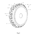
- FIG. 2 shows the hobbing tool 2 from Fig. 1 in a perspective Representation without the workpiece 12. It can be clearly seen how the carrier profile 6 is arranged in a helical line on the lateral surface of the base body 4.
- the carrier profile 6 forms along the base body 4 three courses 11.
- the cutting plates 7, 8, 9 are arranged on the flanks and at the apex of the carrier profile 6.
- the distance of a group of consecutive in the direction of the carrier profile 6 cutting plates 7, 8, 9 increases in one or decreases in the other direction, so that the flanks of the toothing 14 to be produced during a rotation of the Wälzfräswerkmaschines 2 completely by the cutting plates. 7 , 8, 9 are covered.
- the successively increasing or decreasing distance of the cutting plates 7, 8, 9 is in Fig. 1 shown by an example on the support profile 6, to its apex or to its base, extending band.
- FIG. 3 shows a segment of the Wälzfräswerkmaschines 2 in a perspective detail view.
- the cutting plates 7, 8, 9, which are arranged in the top and on the flanks of the carrier profile 6.
- the cutting plates 7, 8, 9 are preceded by chip chambers 5.
- the tapering shape of the cross section of the carrier profile 6 can be clearly seen.
- At 11, three gears formed by the helical course of the carrier profile 6 of the Wälzfrästechnikmaschines 2 can be seen.
- FIG. 4 shows a sectional view of the collar-like carrier profile 6 in the circumferential direction of the base body 4th
- FIG. 5 shows a hobbing tool 2 with a first arrangement inserts 7 in a side view.
- the only difference to the hobbing tool 2 off Fig. 1 is that fewer types of cutting plates are provided.
- FIG. 6 shows a hobbing tool 2 with a second arrangement inserts 8, 9 in a side view.
- the only difference to the hobbing tool 2 off Fig. 1 is that fewer types of cutting plates are provided.
- FIG. 7 shows the hobbing tool 2 from Fig. 1 with a combination of the arrangement of cutting plates 7, 8, 9 made Fig. 5 and Fig. 6 ,
- FIGS. 8 and 9 each show an insert 8, which has a, on the side facing away from the perspective, approximately rectangular, flat base (not shown). In the direction perpendicular to the base surface, a bulge of material forms a total of approximately cuboid base body. On the opposite side of the base surface of the base body of the cutting plate 8 is rounded at two opposite edges. At least one of the edge lying transversely to the rounded edges forms a cutting edge 16.
- a preferably aligned perpendicular to the base bore 18 extends approximately centrally through the body through. Alternatively, the bore 18 may extend at an angle, oblique to the base by the body.
- the cutting plate 8 by means of a screw on the support section 6 of the Wälzfräswerkmaschines 2 (not shown) can be fastened.
- a chip breaker 20 is arranged.
- the chip breaker 20 is inserted as a channel-like depression in the located below the cutting edge 16 side surface of the body and extends at a distance at least in a portion approximately parallel to the cutting edge sixteenth
- FIGS. 10 and 11 show in perspective in each case an insert 7, 8, 9 with a shim 22 and a tuning plate 24th Fig. 10 shows the components in an assembled arrangement, as intended for mounting on a support profile 6 (not shown).
- Fig. 11 shows the arrangement Fig. 10 in an exploded view.
- the shim 22 has an approximately strip-shaped, flat basic shape, wherein a first elongated end of the strip shape tapers into a truncated tip shape.
- the tuning plate 24 has an approximately cuboidal basic shape and has an approximately centrally disposed through hole for attachment to the support section 6 (not shown) by means of a screw 26.
- the Unterlegplatte 22 three through holes are provided, wherein one of the holes for the attachment of the shim 22 to the support section 6 (not shown) is provided by means of a screw 26. In each case via a further bore, the cutting plate 7, 8, 9 and the tuning plate 24 by means of a screw 26 on the support section 6 (not shown) fastened.
- the shim 22 is provided for mounting between the carrier profile 6 (not shown) and the cutting plate 7, 8, 9 with the tuning plate 24. As in Fig. 10 can be seen, are the cutting plate 8, 7, 9 and the tuning plate 24 in the mounted position, each with its base surface on the Unterlegplatte 22.
- the tuning plate 24 is arranged, which rests in the mounted position with a lateral support surface on one side of the cutting plate 7, 8, 9.
- the angular position of the cutting plate 7, 8, 9 with respect to the rotational or longitudinal axis of the base body (not shown) is tunable by the shape of the shim 22 and the shape of the tuning plate 24.
- the angular position of the cutting plate 7, 8, 9 may be specified in particular by a beveled top or bottom of the shim 22 and / or by a tapered bearing surface of the tuning plate 24.
Landscapes
- Engineering & Computer Science (AREA)
- Mechanical Engineering (AREA)
- Gear Processing (AREA)
Priority Applications (1)
| Application Number | Priority Date | Filing Date | Title |
|---|---|---|---|
| EP13002858.2A EP2810728A1 (fr) | 2013-06-03 | 2013-06-03 | Outil de fraisage à cylindre pour la fabrication d'une denture intérieure sur une pièce |
Applications Claiming Priority (1)
| Application Number | Priority Date | Filing Date | Title |
|---|---|---|---|
| EP13002858.2A EP2810728A1 (fr) | 2013-06-03 | 2013-06-03 | Outil de fraisage à cylindre pour la fabrication d'une denture intérieure sur une pièce |
Publications (1)
| Publication Number | Publication Date |
|---|---|
| EP2810728A1 true EP2810728A1 (fr) | 2014-12-10 |
Family
ID=48576183
Family Applications (1)
| Application Number | Title | Priority Date | Filing Date |
|---|---|---|---|
| EP13002858.2A Withdrawn EP2810728A1 (fr) | 2013-06-03 | 2013-06-03 | Outil de fraisage à cylindre pour la fabrication d'une denture intérieure sur une pièce |
Country Status (1)
| Country | Link |
|---|---|
| EP (1) | EP2810728A1 (fr) |
Citations (9)
| Publication number | Priority date | Publication date | Assignee | Title |
|---|---|---|---|---|
| DE1083620B (de) | 1959-10-07 | 1960-06-15 | Rohde & Doerrenberg | Waelzfraeser fuer Innenverzahnung |
| DE1124786B (de) | 1958-12-16 | 1962-03-01 | Fritz Kleinstueck | Doppelkegeliger, schraubenfoermiger Abwaelzfraeser oder -schleifkoerper zur Herstellung von gerad- und schraegverzahnten, evolventenfoermigen Innenzahnkraenzen |
| DE2827145A1 (de) | 1977-06-22 | 1979-01-04 | Masato Prof Ainoura | Kugelfoermiger waelzfraeser zur herstellung von zahnraedern |
| DE3707664C1 (de) * | 1987-03-10 | 1988-10-13 | Liebherr Verzahntech Gmbh | Werkzeugmaschine zum Feinbearbeiten der Zahnflanken von vorverzahnten Zahnraedern |
| DE202006001112U1 (de) * | 2006-01-25 | 2006-03-23 | Fette Gmbh | Wälzfräser |
| CN101066568A (zh) | 2007-06-01 | 2007-11-07 | 燕山大学 | 椭球形内齿轮滚刀 |
| EP2260964A1 (fr) | 2009-06-04 | 2010-12-15 | Vereinigte Pignons Fabriken AG | Procédé et dispositif destinés à la fabrication d'une denture intérieure |
| US20120207553A1 (en) * | 2011-02-11 | 2012-08-16 | Sandvik Intellectual Property Ab | Milling Tool for Gear Milling |
| US20120257935A1 (en) * | 2011-04-08 | 2012-10-11 | Sture Sjoeoe | Milling tool, and milling insert kit |
-
2013
- 2013-06-03 EP EP13002858.2A patent/EP2810728A1/fr not_active Withdrawn
Patent Citations (10)
| Publication number | Priority date | Publication date | Assignee | Title |
|---|---|---|---|---|
| DE1124786B (de) | 1958-12-16 | 1962-03-01 | Fritz Kleinstueck | Doppelkegeliger, schraubenfoermiger Abwaelzfraeser oder -schleifkoerper zur Herstellung von gerad- und schraegverzahnten, evolventenfoermigen Innenzahnkraenzen |
| DE1083620B (de) | 1959-10-07 | 1960-06-15 | Rohde & Doerrenberg | Waelzfraeser fuer Innenverzahnung |
| DE2827145A1 (de) | 1977-06-22 | 1979-01-04 | Masato Prof Ainoura | Kugelfoermiger waelzfraeser zur herstellung von zahnraedern |
| US4202222A (en) | 1977-06-22 | 1980-05-13 | Masato Ainoura | Method for preparation of spherical hob for generation of gear |
| DE3707664C1 (de) * | 1987-03-10 | 1988-10-13 | Liebherr Verzahntech Gmbh | Werkzeugmaschine zum Feinbearbeiten der Zahnflanken von vorverzahnten Zahnraedern |
| DE202006001112U1 (de) * | 2006-01-25 | 2006-03-23 | Fette Gmbh | Wälzfräser |
| CN101066568A (zh) | 2007-06-01 | 2007-11-07 | 燕山大学 | 椭球形内齿轮滚刀 |
| EP2260964A1 (fr) | 2009-06-04 | 2010-12-15 | Vereinigte Pignons Fabriken AG | Procédé et dispositif destinés à la fabrication d'une denture intérieure |
| US20120207553A1 (en) * | 2011-02-11 | 2012-08-16 | Sandvik Intellectual Property Ab | Milling Tool for Gear Milling |
| US20120257935A1 (en) * | 2011-04-08 | 2012-10-11 | Sture Sjoeoe | Milling tool, and milling insert kit |
Similar Documents
| Publication | Publication Date | Title |
|---|---|---|
| DE10330474B4 (de) | Vorrichtung zur Herstellung eines Zahnrads aus einem Zahnradrohling | |
| EP2243582B1 (fr) | Procédé et dispositif d'élimination d'un appareil secondaire sur une roue de pièce usinée interdigitée à l'avant | |
| DE69009018T2 (de) | Fräswerkzeuge. | |
| DE102009016257B4 (de) | Wälzfräser | |
| EP0085176B1 (fr) | Tête porte-lame pour machine à tailler les roues dentées | |
| EP3694670B1 (fr) | Outil de taillage en développante | |
| DE102015106354A1 (de) | Wälzschälverfahren und Schneidwerkzeug zur Erzeugung zumindest teilverrundeter Zahnköpfe | |
| DE102011055210B4 (de) | Werkzeug zur Gewindeherstellung | |
| DE102007015357A1 (de) | Verfahren und Vorrichtung zum Verzahnen von Werkstücken durch Wälzschälen und zugehöriger Schneidvorrichtung | |
| EP2629917A1 (fr) | Fraise pour dent et procédé de fraisage des dents d'éléments d'engrenage à dents | |
| WO2021121730A1 (fr) | Outil et procédé d'usinage de pièce | |
| EP1402981A1 (fr) | Procédé et dispositif de fabrication d'un pied d'une pale de turbine en forme de fourchette | |
| DE102019004687A1 (de) | Verfahren zur Herstellung von Zahnflankenmodifikationen an Verzahnungen von Werkstücken sowie Werkzeuge zur Durchführung des Verfahrens | |
| EP3287221B1 (fr) | Procédé de traitement de flancs de dents de pièces d'usinage d'accouplement plan selon un procédé de pièces individuelles semi-complètes | |
| WO2010094264A1 (fr) | Outil de fraisage doté d'une alimentation en agent de refroidissement/de lubrification située à l'intérieur de celui-ci | |
| DE20320294U1 (de) | Vorrichtung zur Herstellung eines Zahnrads | |
| EP2537616A1 (fr) | Procédé robuste de taillage de cylindres et dispositif correspondant doté d'un outil de taillage de cylindres | |
| DE102017102473B4 (de) | Fräswerkzeug, insbesondere Tannenbaumfräser, und Herstellungsverfahren für ein Fräswerkzeug | |
| DE3633553A1 (de) | Aussengewindeschneidwerkzeug | |
| EP2514692A1 (fr) | Roue à rayons | |
| DE102018118959B3 (de) | Trennscheibe | |
| EP3795316B1 (fr) | Tête d'outil d'un outil d'usinage | |
| EP3477127B1 (fr) | Vis destinée à être vissée dans un trou de forage | |
| DE102010025148A1 (de) | Spanabhebendes Werkzeug | |
| EP2810728A1 (fr) | Outil de fraisage à cylindre pour la fabrication d'une denture intérieure sur une pièce |
Legal Events
| Date | Code | Title | Description |
|---|---|---|---|
| PUAI | Public reference made under article 153(3) epc to a published international application that has entered the european phase |
Free format text: ORIGINAL CODE: 0009012 |
|
| 17P | Request for examination filed |
Effective date: 20130603 |
|
| AK | Designated contracting states |
Kind code of ref document: A1 Designated state(s): AL AT BE BG CH CY CZ DE DK EE ES FI FR GB GR HR HU IE IS IT LI LT LU LV MC MK MT NL NO PL PT RO RS SE SI SK SM TR |
|
| AX | Request for extension of the european patent |
Extension state: BA ME |
|
| R17P | Request for examination filed (corrected) |
Effective date: 20150609 |
|
| RBV | Designated contracting states (corrected) |
Designated state(s): AL AT BE BG CH CY CZ DE DK EE ES FI FR GB GR HR HU IE IS IT LI LT LU LV MC MK MT NL NO PL PT RO RS SE SI SK SM TR |
|
| GRAP | Despatch of communication of intention to grant a patent |
Free format text: ORIGINAL CODE: EPIDOSNIGR1 |
|
| STAA | Information on the status of an ep patent application or granted ep patent |
Free format text: STATUS: GRANT OF PATENT IS INTENDED |
|
| INTG | Intention to grant announced |
Effective date: 20180322 |
|
| STAA | Information on the status of an ep patent application or granted ep patent |
Free format text: STATUS: THE APPLICATION IS DEEMED TO BE WITHDRAWN |
|
| 18D | Application deemed to be withdrawn |
Effective date: 20180802 |