EP2810812A1 - Hauptstromkreissystem für elektroschienenfahrzeuge - Google Patents
Hauptstromkreissystem für elektroschienenfahrzeuge Download PDFInfo
- Publication number
- EP2810812A1 EP2810812A1 EP12867430.6A EP12867430A EP2810812A1 EP 2810812 A1 EP2810812 A1 EP 2810812A1 EP 12867430 A EP12867430 A EP 12867430A EP 2810812 A1 EP2810812 A1 EP 2810812A1
- Authority
- EP
- European Patent Office
- Prior art keywords
- current power
- power supply
- alternating
- direct
- current
- Prior art date
- Legal status (The legal status is an assumption and is not a legal conclusion. Google has not performed a legal analysis and makes no representation as to the accuracy of the status listed.)
- Granted
Links
Images




Classifications
-
- H—ELECTRICITY
- H02—GENERATION; CONVERSION OR DISTRIBUTION OF ELECTRIC POWER
- H02J—ELECTRIC POWER NETWORKS; CIRCUIT ARRANGEMENTS OR SYSTEMS FOR SUPPLYING OR DISTRIBUTING ELECTRIC POWER; SYSTEMS FOR STORING ELECTRIC ENERGY
- H02J4/00—Circuit arrangements for mains or distribution networks not specified as AC or DC; Circuit arrangements for mains or distribution networks combining AC and DC sections or sub-networks
- H02J4/20—Networks integrating separated AC and DC power sections
- H02J4/25—Networks integrating separated AC and DC power sections for transfer of electric power between AC and DC networks, e.g. for supplying the DC section within a load from an AC mains system
-
- B—PERFORMING OPERATIONS; TRANSPORTING
- B60—VEHICLES IN GENERAL
- B60L—PROPULSION OF ELECTRICALLY-PROPELLED VEHICLES; SUPPLYING ELECTRIC POWER FOR AUXILIARY EQUIPMENT OF ELECTRICALLY-PROPELLED VEHICLES; ELECTRODYNAMIC BRAKE SYSTEMS FOR VEHICLES IN GENERAL; MAGNETIC SUSPENSION OR LEVITATION FOR VEHICLES; MONITORING OPERATING VARIABLES OF ELECTRICALLY-PROPELLED VEHICLES; ELECTRIC SAFETY DEVICES FOR ELECTRICALLY-PROPELLED VEHICLES
- B60L9/00—Electric propulsion with power supply external to the vehicle
- B60L9/16—Electric propulsion with power supply external to the vehicle using AC induction motors
- B60L9/18—Electric propulsion with power supply external to the vehicle using AC induction motors fed from DC supply lines
-
- B—PERFORMING OPERATIONS; TRANSPORTING
- B60—VEHICLES IN GENERAL
- B60L—PROPULSION OF ELECTRICALLY-PROPELLED VEHICLES; SUPPLYING ELECTRIC POWER FOR AUXILIARY EQUIPMENT OF ELECTRICALLY-PROPELLED VEHICLES; ELECTRODYNAMIC BRAKE SYSTEMS FOR VEHICLES IN GENERAL; MAGNETIC SUSPENSION OR LEVITATION FOR VEHICLES; MONITORING OPERATING VARIABLES OF ELECTRICALLY-PROPELLED VEHICLES; ELECTRIC SAFETY DEVICES FOR ELECTRICALLY-PROPELLED VEHICLES
- B60L1/00—Supplying electric power to auxiliary equipment of vehicles
-
- B—PERFORMING OPERATIONS; TRANSPORTING
- B60—VEHICLES IN GENERAL
- B60L—PROPULSION OF ELECTRICALLY-PROPELLED VEHICLES; SUPPLYING ELECTRIC POWER FOR AUXILIARY EQUIPMENT OF ELECTRICALLY-PROPELLED VEHICLES; ELECTRODYNAMIC BRAKE SYSTEMS FOR VEHICLES IN GENERAL; MAGNETIC SUSPENSION OR LEVITATION FOR VEHICLES; MONITORING OPERATING VARIABLES OF ELECTRICALLY-PROPELLED VEHICLES; ELECTRIC SAFETY DEVICES FOR ELECTRICALLY-PROPELLED VEHICLES
- B60L7/00—Electrodynamic brake systems for vehicles in general
- B60L7/02—Dynamic electric resistor braking
- B60L7/06—Dynamic electric resistor braking for vehicles propelled by AC motors
-
- B—PERFORMING OPERATIONS; TRANSPORTING
- B60—VEHICLES IN GENERAL
- B60L—PROPULSION OF ELECTRICALLY-PROPELLED VEHICLES; SUPPLYING ELECTRIC POWER FOR AUXILIARY EQUIPMENT OF ELECTRICALLY-PROPELLED VEHICLES; ELECTRODYNAMIC BRAKE SYSTEMS FOR VEHICLES IN GENERAL; MAGNETIC SUSPENSION OR LEVITATION FOR VEHICLES; MONITORING OPERATING VARIABLES OF ELECTRICALLY-PROPELLED VEHICLES; ELECTRIC SAFETY DEVICES FOR ELECTRICALLY-PROPELLED VEHICLES
- B60L7/00—Electrodynamic brake systems for vehicles in general
- B60L7/22—Dynamic electric resistor braking, combined with dynamic electric regenerative braking
-
- B—PERFORMING OPERATIONS; TRANSPORTING
- B60—VEHICLES IN GENERAL
- B60L—PROPULSION OF ELECTRICALLY-PROPELLED VEHICLES; SUPPLYING ELECTRIC POWER FOR AUXILIARY EQUIPMENT OF ELECTRICALLY-PROPELLED VEHICLES; ELECTRODYNAMIC BRAKE SYSTEMS FOR VEHICLES IN GENERAL; MAGNETIC SUSPENSION OR LEVITATION FOR VEHICLES; MONITORING OPERATING VARIABLES OF ELECTRICALLY-PROPELLED VEHICLES; ELECTRIC SAFETY DEVICES FOR ELECTRICALLY-PROPELLED VEHICLES
- B60L9/00—Electric propulsion with power supply external to the vehicle
- B60L9/16—Electric propulsion with power supply external to the vehicle using AC induction motors
- B60L9/30—Electric propulsion with power supply external to the vehicle using AC induction motors fed from different kinds of power-supply lines
-
- B—PERFORMING OPERATIONS; TRANSPORTING
- B60—VEHICLES IN GENERAL
- B60W—CONJOINT CONTROL OF VEHICLE SUB-UNITS OF DIFFERENT TYPE OR DIFFERENT FUNCTION; CONTROL SYSTEMS SPECIALLY ADAPTED FOR HYBRID VEHICLES; ROAD VEHICLE DRIVE CONTROL SYSTEMS FOR PURPOSES NOT RELATED TO THE CONTROL OF A PARTICULAR SUB-UNIT
- B60W10/00—Conjoint control of vehicle sub-units of different type or different function
-
- B—PERFORMING OPERATIONS; TRANSPORTING
- B60—VEHICLES IN GENERAL
- B60L—PROPULSION OF ELECTRICALLY-PROPELLED VEHICLES; SUPPLYING ELECTRIC POWER FOR AUXILIARY EQUIPMENT OF ELECTRICALLY-PROPELLED VEHICLES; ELECTRODYNAMIC BRAKE SYSTEMS FOR VEHICLES IN GENERAL; MAGNETIC SUSPENSION OR LEVITATION FOR VEHICLES; MONITORING OPERATING VARIABLES OF ELECTRICALLY-PROPELLED VEHICLES; ELECTRIC SAFETY DEVICES FOR ELECTRICALLY-PROPELLED VEHICLES
- B60L2200/00—Type of vehicles
- B60L2200/26—Rail vehicles
-
- B—PERFORMING OPERATIONS; TRANSPORTING
- B60—VEHICLES IN GENERAL
- B60L—PROPULSION OF ELECTRICALLY-PROPELLED VEHICLES; SUPPLYING ELECTRIC POWER FOR AUXILIARY EQUIPMENT OF ELECTRICALLY-PROPELLED VEHICLES; ELECTRODYNAMIC BRAKE SYSTEMS FOR VEHICLES IN GENERAL; MAGNETIC SUSPENSION OR LEVITATION FOR VEHICLES; MONITORING OPERATING VARIABLES OF ELECTRICALLY-PROPELLED VEHICLES; ELECTRIC SAFETY DEVICES FOR ELECTRICALLY-PROPELLED VEHICLES
- B60L2210/00—Converter types
- B60L2210/30—AC to DC converters
-
- B—PERFORMING OPERATIONS; TRANSPORTING
- B60—VEHICLES IN GENERAL
- B60L—PROPULSION OF ELECTRICALLY-PROPELLED VEHICLES; SUPPLYING ELECTRIC POWER FOR AUXILIARY EQUIPMENT OF ELECTRICALLY-PROPELLED VEHICLES; ELECTRODYNAMIC BRAKE SYSTEMS FOR VEHICLES IN GENERAL; MAGNETIC SUSPENSION OR LEVITATION FOR VEHICLES; MONITORING OPERATING VARIABLES OF ELECTRICALLY-PROPELLED VEHICLES; ELECTRIC SAFETY DEVICES FOR ELECTRICALLY-PROPELLED VEHICLES
- B60L2210/00—Converter types
- B60L2210/40—DC to AC converters
-
- Y—GENERAL TAGGING OF NEW TECHNOLOGICAL DEVELOPMENTS; GENERAL TAGGING OF CROSS-SECTIONAL TECHNOLOGIES SPANNING OVER SEVERAL SECTIONS OF THE IPC; TECHNICAL SUBJECTS COVERED BY FORMER USPC CROSS-REFERENCE ART COLLECTIONS [XRACs] AND DIGESTS
- Y02—TECHNOLOGIES OR APPLICATIONS FOR MITIGATION OR ADAPTATION AGAINST CLIMATE CHANGE
- Y02T—CLIMATE CHANGE MITIGATION TECHNOLOGIES RELATED TO TRANSPORTATION
- Y02T10/00—Road transport of goods or passengers
- Y02T10/60—Other road transportation technologies with climate change mitigation effect
- Y02T10/72—Electric energy management in electromobility
Definitions
- the present invention relates to an electric motor vehicle main circuit system.
- the applicant performed document searches for technologies concerning an electric motor vehicle main circuit system adaptable to a plurality of multiple power supplies by an alternating current and a direct current like the multiple power supply explained above, more specifically, both of an alternating-current power supply and a direct-current supply and adaptable to an AC-DC multiple power supply in which at least one of the alternating-current power supply and the direct-current power supply is provided in a plural form.
- the inventor has not found an appropriate document including the related art.
- the "plural" in this context means that both of the direct-current power supply and the alternating-current power supply are distinguished according to a difference in an overhead wire voltage.
- Patent Literature 1 discloses a technology for unitizing devices in a control device to attain a reduction in a work time and a restoration time from a failure.
- Patent Literature 2 discloses a technology for securing compatibility among units in a control device to solve a problem of an inductive interference when the units are manufactured by a plurality of manufactures.
- the present invention has been devised in view of the above and it is an object of the present invention to provide an electric motor vehicle main circuit system that can attain common use of components and is excellent in maintainability.
- the present invention provides an electric motor vehicle main circuit system that controls an electric motor for electric motor vehicle driving, alternating-current power by a first alternating-current power supply, alternating-current power by a second alternating-current power supply having a higher output voltage than the first alternating-current power supply, and direct-current power by a first direct-current power supply being supplied to an overhead wire
- the electric motor vehicle main circuit system including an AC-DC switching circuit that switches a supply destination of electric power according to a type of supplied power from the overhead wire; a transformer that includes two tap positions on a secondary winding wire side, steps down an input alternating-current voltage, and outputs a desired alternating-current voltage from the two tap positions; a tap changer that switches the tap positions of the transformer; a converter that converts an alternating-current voltage output by the tap changer into a desired direct-current voltage; an alternating-current contactor that opens and closes a power supply path between the tap changer and the converter; a filter capacitor that
- the electric motor vehicle main circuit system can operate receiving power supply from an AC-DC multiple power supply in which at least one of an alternating-current power supply and a direct-current power supply is provided in a plurality of types.
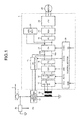
- FIG. 1 is a diagram of a configuration example of an electric motor vehicle driving system including an electric motor vehicle main circuit system according to a first embodiment of the present invention.
- the electric motor vehicle driving system according to the first embodiment includes an electric motor vehicle main circuit system 1 and a current collector 11, an AC-DC switching circuit 12, a transformer 14, and an electric motor (a motor) 28 for electric motor driving arranged around the electric motor vehicle main circuit system 1.
- the electric motor vehicle main circuit system 1 includes the transformer 14, a tap changer 15, an AC (alternating-current) contactor 16, a converter (hereinafter referred to as “CNV") 17, an FC 18 functioning as a first filter capacitor (hereinafter referred to as “FC”), a DC (direct-current) contactor 19, a boost chopper (hereinafter referred to as “CH”) 21, an FC 22 functioning as a second FC, a brake chopper (hereinafter referred to as "BCH”) 23, an inverter (hereinafter referred to as "INV”) 24, an APS & BCG 25 mounted with an auxiliary power supply (hereinafter referred to as "APS”) and a battery charger (hereinafter referred to as "BCG”), and a control section 30 that controls these devices or circuit sections.
- CNV alternating-current
- FC first filter capacitor
- FC DC (direct-current) contactor 19
- CH boost chopper
- FC 22 functioning as a second FC
- BCH brake chopper
- ISV in
- a voltage detector 29 that detects the voltage of an overhead wire 2 is connected between the current collector 11 and the AD-DC switching circuit 12.
- the motor 28 is connected to the INV 24 arranged at an output end of the electric motor vehicle main circuit system 1. Note that, as the motor 28, an induction motor or a synchronous motor is suitable.
- the AC-DC switching circuit 12 switches a supply destination of electric power according to a type of supplied power (a supply power source) from the overhead wire 2. More specifically, when alternating-current power (e.g., AC15kV-16.7Hz or AC25kV-50Hz) is supplied from the overhead wire 2, the AC-DC switching circuit 12 switches an output destination to the transformer 14. When direct-current power (e.g., DC1.5kV or DC3.0kV) is supplied from the overhead wire 2, the AC-DC switching circuit 12 switches the output destination to the DC contactor 19. Note that the switching of the power supply destination in the AC-DC switching circuit 12 is automatically performed.
- alternating-current power e.g., AC15kV-16.7Hz or AC25kV-50Hz
- direct-current power e.g., DC1.5kV or DC3.0kV
- the transformer 14 includes a primary winding wire and a secondary winding wire and includes two contacts A and B as tap positions in the secondary winding wire.
- the transformer 14 steps down an input voltage and outputs a desired voltage from the two tap positions.
- the tap changer 15 switches the two tap positions on the basis of a control signal output from a control section explained below and according to a type of a supply power source. Note that a relation between the tap positions and the type of the supply power source is explained below.
- the AC contactor 16 is arranged between the tap changer 15 and the CNV 17.
- the AC contactor 16 opens and closes a power supply path between these components.
- the CNV 17 is provided on the output side of the AC contactor 16.
- the FC 18 is provided on the output side of the CNV 17.
- the CNV 17 is a power converting section that converts alternating-current power (an alternating-current voltage) into desired direct-current power (a desired direct-current voltage).
- the direct-current power converted by the CNV 17 is accumulated in the FC 18 as charges.
- the DC contactor 19 is connected between a positive side direct-current bus 20a and a negative side direct-current bus 20b that electrically connect the FC 18 (or the CNV 17) and the CH 21 (or the INV 24). According to the connection, the DC contactor 19 opens and closes a power supply path between the AC-DC switching circuit 12 and the CH 21. According to the connection, when the DC contactor 19 closes the path, direct-current power (a direct-current voltage) output by the AC-DC switching circuit 12 is supplied (applied) to the CH 21.
- the CH 21 is a circuit for stepping up the direct-current voltage applied via the DC contactor 19, that is, a DC/DC converter having a boosting function. Note that, when the CH 21 operates as a booster circuit, a not-shown switching element included in the CH 21 operates. On the other hand, when the CH 21 is not caused to function, the CH 21 operates as a mere through-circuit (a circuit that transmits electric power without affecting other circuit operations). Note that a relation between the operation of the CH 21 and the type of the supply power source is explained below.
- the BCH 23 is provided on the output side of the FC 22.
- the INV 24 is provided on the output side of the BCH 23.
- the INV 24 is a power converting section that converts direct-current power (a direct-current voltage) into alternating-current power (an alternating-current voltage) having a desired voltage and a desired frequency.
- the electric power converted by the INV 24 is supplied to the motor 28.
- the motor 28 rotates to give a driving force to the electric motor vehicle.
- the BCH 23 is a circuit that consumes excess power that cannot be regenerated to the overhead wire 2 side when the motor 28 operates as a generator.
- the APS & BCG 25 is a component including a power supply (battery) device that supplies electric power to devices (e.g., a brake device, a lighting device, a door opening and closing device, and an air conditioning device; hereinafter referred to as "auxiliary machines") other than the motor 28, which is a main electric motor, and a charging device for charging the power supply device.
- a power supply battery
- auxiliary machines air conditioning device
- FIG. 1 the APS & BCG 25 is configured to operate using output power of the CH 21.
- the control section 30 monitors a detected voltage of the voltage detector 29 as overhead wire voltage information VG to determine the type of the supply power source.
- Command information such as an operation command or a control command by a commander is input to the control section 30 as a motorman's cab command CMD.
- the control section 30 generates, on the basis of the overhead wire voltage information VG and the motorman's cab command CMD, a tap changer switching command TCG for switching the tap positions of the tap changer 15, an AC contactor opening and closing command ACCG for controlling opening and closing of the AC contactor 16, a DC contactor opening and closing command DCCG for controlling opening and closing of the DC contactor 19, a CNV operation command GSC for the CNV 17, and a CH operation command CHSC for the CH 21 and controls the respective sections.
- FIG. 2 is a diagram for explaining the operation performed when the first power supply (AC15kV-16.7Hz) is used as the supply power source. Specifically, in the figure, parts (units) that operate receiving the supply of the first power supply are shown on the configuration diagram of FIG. 1 . In FIG. 2 , parts indicated by solid lines are parts related to the operation. Parts indicated by broken lines are parts not caused to operate.
- the first power supply is an alternating-current power supply. Therefore, alternating-current power from the first power supply is supplied to the transformer 14.
- the tap positions of the tap changer 15 are switched to the A side.
- the alternating-current power is supplied to the CNV 17 through the AC contactor 16 controlled to ON.
- the DC contactor 19 is controlled to OFF.
- a chopper operation of the CH 21 is stopped. Because the CH 21 stops the chopper operation, the CH 21 performs a through-operation.
- An output of the CNV 17 is accumulated in the FCs 18 and 22.
- An output voltage of the CNV 17 is applied to the INV 24.
- the INV 24 supplies required electric power to the motor 28 using accumulated charges of the FCs 18 and 22 and drives the motor 28.
- the APS & BCG 25 supplies required electric power to the auxiliary machines using the accumulated charges of the FCs 18 and 22 and causes the auxiliary machines to operate.
- FIG. 3 is a diagram for explaining an operation performed when the second power supply (AC25kV-50Hz) is used as the supply power source. Specifically, in the figure, parts that operate receiving the supply of the second power supply are shown on the configuration diagram of FIG. 1 . In FIG. 3 , parts indicated by solid lines are parts related to the operation. Parts indicated by broken lines are parts not caused to operate.
- the second power supply is also an alternating-current power supply. Therefore, alternating-current power from the second power supply is supplied to the transformer 14.
- the tap positions of the tap changer 15 are switched to the B side. Because the tap positions of the tap changer 15 are switched to the B side, even when the second power supply having a higher output voltage than the first power supply is applied, an output voltage from the secondary winding wire of the transformer 14 can be equivalent to the output voltage output when the first power supply is applied. Consequently, an applied voltage to the CNV 17 is equivalent to the applied voltage in the case of the first power supply.
- the units can be used in common. Note that the subsequent operations are the same as the operations in the case of the first power supply. Detailed explanation of the operations is omitted.
- the transformer 14 only has to be designed to be adapted to the first power supply having a low power supply frequency.
- the transformer 14 designed in this way can also be used for the second power supply.
- FIG. 4 is a diagram for explaining the operation performed when the third power supply (DC1.5kV) is used as the supply power source. Specifically, in the figure, parts that operate receiving the supply of the third power supply are shown on the configuration diagram of FIG. 1 . In FIG. 4 , parts indicated by solid lines are parts related to the operation. Parts indicated by broken lines are parts not caused to operate or parts unrelated to the operation.
- the third power supply is a direct-current power supply. Therefore, direct-current power from the third power supply is supplied to the CH 21 through the DC contactor 19 controlled to ON.
- the tap positions of the tap changer 15 are arbitrary.
- the AC contactor 16 is controlled to OFF.
- the CNV 17 does not operate.
- the CH 21 performs a chopper operation and steps up an input voltage. An output of the CH 21 is accumulated in the FC 22. An output voltage of the CH 21 is applied to the INV 24.
- the INV 24 supplies required electric power to the motor 28 using accumulated charges of the FC 22 and drives the motor 28.
- the APS & BCG 25 also supplies required electric power to the auxiliary machines using the accumulated charges of the FC 22 and causes the auxiliary machines to operate.
- FIG. 5 is a diagram for explaining the operation performed when the fourth power supply (DC3.0kV) is used as the supply power source. Specifically, in the figure, parts that operate receiving the supply of the fourth power supply are shown on the configuration diagram of FIG. 1 . In FIG. 5 , parts indicated by solid lines are parts related to the operation. Parts indicated by broken lines are parts not caused to operate or parts unrelated to the operation.
- the fourth power supply is also a direct-current power supply. Therefore, direct-current power from the fourth power supply is also supplied to the CH 21 through the DC contactor 19 controlled to ON.
- the states or the operations of the tap changer 15, the AC contactor 16, and the CNV 17 indicated by the broken lines are the same as the states or the operations in the case of the third power supply.
- the fourth power supply except when it is necessary to cause the CH 21 to operate, the CH 21 is caused to perform a through-operation without being cause to operate. This is because the voltage of the fourth power supply is higher than the voltage of the third power supply and, therefore, it is unnecessary to cause the CH 21 to perform a boosting operation.
- an applied voltage to the INV 24 is equivalent to the applied voltage in the case of the third power supply.
- the units can be used in common. Note that the subsequent operations are the same as the operations in the case of the third power supply. Detailed explanation of the operations is omitted.
- the operations explained above are respective operations for the first to fourth power supplies.
- electric power supplied at a time is supplied from any one of the first to fourth power supplies. Therefore, the electric motor vehicle main circuit system can be adapted to all the power supplies.
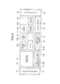
- FIG. 6 is a diagram of an arrangement example in which the electric motor vehicle main circuit system configured as shown in FIG. 1 is viewed from above or below a vehicle when the electric motor vehicle main circuit system is mounted on an under-floor section or a roof of the vehicle.
- the electric motor vehicle main circuit system shown in FIG. 1 is arranged to be divided into first to ninth parts.
- a first part 51 corresponds to a water cooling device 61
- a second part 52 corresponds to an APS & BCG power unit 62
- a third part 53 corresponds to a discharge resistor 63A and an APS inductor 63B
- a fourth part 54 corresponds to an INV & BCH power unit 64A and a CNV power unit 64B
- a fifth part 55 corresponds to an FC unit 65
- a sixth part 56 corresponds to an APS & BCG output circuit section 66
- a seventh part 57 corresponds to a tap changer 67A, an AC contactor 67B, and a DC contactor 67C
- an eighth part 58 corresponds to a control module 68
- a ninth part 59 corresponds to a CH circuit section 69.
- FIG. 6 What is characteristic in the configuration shown in FIG. 6 is that, in some component, a part of a circuit function is arranged to be separated and, in another component, a plurality of circuit functions are arranged to be integrated.
- the APS & BCG 25 shown in FIG. 1 is separated into the APS & BCG power unit 62, the APS inductor 63B, and the APS & BCG output circuit section 66, which are three circuit sections, and respectively arranged as different parts.
- the CNV 17, the INV 24, and the BCH 23 are arranged to be integrated in the fourth part 54 as the INV & BCH power unit 64A and the CNV power unit 64B.
- FIG. 7 is a diagram of a list in a table format of operation modes corresponding to the first to fourth power supplies.
- the operation modes are divided into fifteen cases, i.e., a case 1 to a case 15, according to which of the first power supply (a power supply 1) to the fourth power supply (a power supply 4) the operation modes correspond.
- black circles mean that the cases correspond to the power supplies indicated by the black circles.
- the black circles mean that the case 1 corresponds to all the power supplies 1 to 4.
- the black circles mean that the case 3 corresponds to the power supplies 1 and 2, which are two alternating-current power supply, and the power supply 4, which is one of direct-current power supplies (conversely, the case 3 does not correspond to the power supply 3).
- the other cases can be explained the same.
- the AC contactor is controlled to ON when the AC contactor operates with the power supplies 1 and 2, which are alternating-current power supplies.
- the AC contactor is controlled to OFF when the AC contactor operates with the power supplies 3 and 4, which are direct-current power supplies. Therefore, the AC contactor is controlled to ON in the cases not including a direct-current power supply such as the cases 6, 12, and 13.
- the AC contactor is controlled to OFF in cases not including an alternating-current power supply such as the cases 11, 14, and 15.
- the AC contactor is controlled to be switched to any one of ON and OFF in other cases.
- the DC contactor is in a relation opposite to the relation of the AC contactor.
- the DC contactor is controlled to OFF in cases not including a direct-current power supply such as the cases 6, 12, and 13.
- the DC contactor is controlled to ON in cases not including an alternating-current power supply such as the cases 11, 14, and 15.
- the DC contactor is controlled to be switched to any one of ON and OFF in other cases.
- the tap positions of the tap changer have a meaning when a power supply is the alternating-current power supplies (the power supplies 1 and 2). Therefore, in the cases not including an alternating-current power supply such as the cases 11, 14, and 15, the tap positions can be any positions.
- the tap positions are fixed. For example, in cases including only the power supply 1 as the alternating-current power supply such as the cases 4, 7, 8, and 12, the tap positions are fixed to A. In cases including only the power supply 2 as the alternating-current power supply such as the cases 5, 9, 10, and 13, the tap positions are fixed to B. In the other cases, the tap positions are controlled to be switched to any one of A and B.
- the CNV operation command CGSC is output as appropriate (ON) when the power supply is the alternating-current power supplies (the power supplies 1 and 2).
- the CNV operation command CGSC is always controlled to OFF when the power supply is the direct-current power supplies (the power supplies 3 and 4). That is, the CNV operation command CGSC is output in the cases 6, 12, and 13, always controlled to OFF in the cases 11, 14, and 15, and switched to be always controlled to OFF or output as appropriate in the other cases.
- the CH operation command CHSC is output as appropriate (ON) in the case of the power supply 3 and is always controlled to OFF in the case of the power supplies other than the power supply 3. That is, the CH operation command CHSC is output as appropriate without being always controlled to OFF only in the case 14, always controlled to OFF in the cases 3, 6, 8, 10, 12, 13, and 15, and switched to be always controlled to be OFF or output as appropriate in the other cases.
- the electric motor vehicle main circuit system shown in FIG. 1 satisfies the request.
- An electric motor vehicle designed to operate with four types of power supplies like the electric motor vehicle main circuit system shown in FIG. 1 can meet various requests. For example, it is assumed that there is a request to apply the electric motor vehicle main circuit system to an electric motor vehicle that travels among the route "a" in which the power supply 1 is used, the route "b" in which the power supply 2 is used, and the route "d” in which the power supply 4 is used. In this case, the electric motor vehicle main circuit system shown in FIG. 1 can be directly used. However, the CH 21 can be removed from the configuration shown in FIG. 1 . In this case, even if the CH 21 is removed, a direct-current bus between the FC 18 and the FC 22 only has to be electrically connected. A structural design change is little.
- the electric motor vehicle main circuit system that operates receiving the supplied power from the power supply 1, the power supply 2, and the power supply 4 can be built as a basic specification.
- the cases shown in FIG. 7 can be grasped as a system developed from the basis specification. This case corresponds to the case 3 shown in FIG. 7 . Therefore, as expansion from the case 3 to the case 1, the system only has to be developed according to an idea for adding the CH 21 between the FC 18 and the FC 22 and adding a function for controlling the CH 21 to the control section 30.
- the AC-DC switching circuit 12 when there is a request to apply the electric motor vehicle main circuit system to an electric motor vehicle that travels between the route "c" in which the power supply 3 is used and the route "d” in which the power supply 4 is used, the AC-DC switching circuit 12, the tap changer 15, the AC contactor 16, the CNV 17, and the FC 18 can be removed from the configuration shown in FIG. 1 .
- the arrangement example of the electric motor vehicle main circuit system shown in FIG. 6 can be changed as shown in FIG. 9 .
- the CNV power unit 64B and the tap changer 67A can be removed and the FC unit 65 can be reduced in size.
- the electric motor vehicle main circuit system adaptable to the two types of alternating-current power supplies, that is, the first and second power supplies (the power supplies 1 and 2) and the two kinds of direct-current power supplies, that is, the third and fourth power supplies (the power supplies 3 and 4) is explained.
- the electric motor vehicle main circuit system adaptable to a more variety of alternating-current power supplies and direct-current power supplies by applying the technical idea of the first embodiment.
- the electric motor vehicle main circuit system can provide a system configuration adaptable to various combinations of the power supplies (the case 1 to the case 15). Therefore, there is an effect that it is possible to attain common use of components concerning all the cases, workability of management and maintenance of spare parts is improved, and reliability is improved.
- the combination of the power supplies does not need to be designed every time the power supplies are combined. Therefore, there is an effect that a product manufacturing period is reduced and the electric motor vehicle main circuit system can be easily adapted to a change to other power supplies.
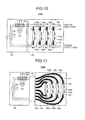
- FIG. 10 is a schematic diagram of a configuration example of the water cooling system according to the second embodiment. The configuration of the water cooling system suitably used in the electric motor vehicle main circuit system shown in FIG. 1 is shown. In FIG.
- a water cooling system 100A includes a water cooling device 101 including a pump 102, a blower 103, and a heat exchanger 104, a main water pipe 106 drawn through a housing 110, which houses the electric motor vehicle main circuit system, from the water cooling device 101 and returning to the water cooling device 101, water cooling plates 108 (108a to 108d) provided on the housing 110 side and mounted with semiconductor elements 105 (105a to 105d), which are bodies to be cooled, and flexible tubes 107 including, at their ends, connectors 109 for connecting the water cooling plates 108 and the main water pipe 106.
- the water cooling plate 108a cools the semiconductor element 105a mounted on the APS & BCG power unit 62.
- the water cooling plate 108b cools the semiconductor element 105b mounted on the INV & BCH power unit 64A.
- the water cooling plate 108c cools the semiconductor element 105c mounted on the CNV power unit 64B.
- the water cooling plate 108d cools the semiconductor element 105d mounted on the CH circuit section 69.
- the main water pipe 106 needs to be a water pipe relatively thick and firm because the main water pipe 106 distributes cooling water to the water cooling plates 108. Therefore, the main water pipe 106 occupies a large space in the housing 110. A degree of freedom of arrangement of the main water pipe 106 is not high. However, for example, when the main water pipe 106 is applied to an apparatus, the specifications of which are clear, like the electric motor vehicle main circuit system shown in FIG. 1 , the main water pipe 106 is not a significant problem.
- FIG. 11 is a schematic diagram of a configuration example different from FIG. 10 of the water cooling system according to the second embodiment.
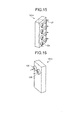
- a water cooling system 100B shown in FIG. 11 the main water pipe 106 provided in the configuration shown in FIG. 10 is removed. Instead, a distribution block 121 is arranged between the water cooling device 101 and the housing 110. Note that a configuration example of the distribution block 121 is shown in FIG. 12 to FIG. 14 .
- each water outlet hole 123 for supplying the cooling water to the water cooling plates 108 and four water inlet holes 124 for returning the cooling water, which receives heat of the water cooling plates 108, to the water cooling device 101 side are provided (see FIGS. 12 and 14 ).
- a water inlet hole 125 for leading the cooling water to the distribution block 121 and a water outlet hole 126 for leading the cooling water, which is distributed from the distribution block 121, to the water cooling device 101 are provided (see FIGS. 12 and 13 ).
- the CH circuit section 69 of the ninth part is unnecessary.
- the water cooling plate 108d and the flexible tube 117 that connects the water cooling plate 108d and the distribution block 121 are removed from the distribution block 121 of the water cooling system 100B (the water outlet hole 123 and the water inlet hole 124 corresponding to the flexible tube 117 are closed). Consequently, a space in the housing 110 is expanded and the maintainability is improved.
- the water cooling system 100B shown in FIG. 11 is effective when a part of the request to the system is changed as explained in the first embodiment.
- the electric motor vehicle is configured that is designed to operate with the first to fourth power supplies, that is, four types of alternating-current and direct-current power supplies and operates only with the two types of direct-current power supplies by the third and the fourth power supplies, it is possible to remove the tap changer 15, the AC contactor 16, the CNV 17, and the FC 18. Therefore, it is possible to arrange the water cooling device 101 in an empty space.
- the main water pipe 106 is used in the water cooling system 100A shown in FIG. 10 . Therefore, it is difficult to move the water cooling device 101 without performing a substantial design change.
- the distribution block 121 and the flexible tubes 117 are used in the water cooling system 100B shown in FIG. 11 . Therefore, the water cooling system 100B can be flexibly adapted to the specification change. It is possible to effectively utilize a limited space in a vehicle control device set in an under-floor section or on a roof of the vehicle. Because the flexible tubes 117 more inexpensive than the main water pipe 106 is used, it is also possible to contribute to a cost reduction.
- the distribution block 121 shown in FIG. 11 a configuration is shown in which the four water outlet holes 123 and the four water inlet holes 124 are linearly disposed in one longitudinal row.
- the four water outlet holes 123 and the four water inlet holes 124 can be disposed in two longitudinal rows.
- the numbers of the water outlet holes 123 and the water inlet holes 124 shown in FIGS. 12 , 14 , and 15 are examples. It goes without saying that the numbers are arbitrary.
- the present invention is useful as an electric motor vehicle main circuit adaptable to a plurality of kinds of AC-DC multiple power supplies.
Landscapes
- Engineering & Computer Science (AREA)
- Power Engineering (AREA)
- Transportation (AREA)
- Mechanical Engineering (AREA)
- Life Sciences & Earth Sciences (AREA)
- Sustainable Development (AREA)
- Sustainable Energy (AREA)
- Chemical & Material Sciences (AREA)
- Combustion & Propulsion (AREA)
- Electric Propulsion And Braking For Vehicles (AREA)
- Dc-Dc Converters (AREA)
- Rectifiers (AREA)
Applications Claiming Priority (1)
| Application Number | Priority Date | Filing Date | Title |
|---|---|---|---|
| PCT/JP2012/052046 WO2013114549A1 (ja) | 2012-01-30 | 2012-01-30 | 電気車主回路システム |
Publications (3)
| Publication Number | Publication Date |
|---|---|
| EP2810812A1 true EP2810812A1 (de) | 2014-12-10 |
| EP2810812A4 EP2810812A4 (de) | 2015-12-23 |
| EP2810812B1 EP2810812B1 (de) | 2019-08-21 |
Family
ID=48778661
Family Applications (1)
| Application Number | Title | Priority Date | Filing Date |
|---|---|---|---|
| EP12867430.6A Active EP2810812B1 (de) | 2012-01-30 | 2012-01-30 | Hauptstromkreissystem für elektroschienenfahrzeuge |
Country Status (7)
| Country | Link |
|---|---|
| US (1) | US9656555B2 (de) |
| EP (1) | EP2810812B1 (de) |
| JP (1) | JP5214065B1 (de) |
| KR (1) | KR101555799B1 (de) |
| CN (1) | CN104080640B (de) |
| IN (1) | IN2014CH06103A (de) |
| WO (1) | WO2013114549A1 (de) |
Cited By (2)
| Publication number | Priority date | Publication date | Assignee | Title |
|---|---|---|---|---|
| FR3112728A1 (fr) * | 2020-07-27 | 2022-01-28 | Alstom Transport Technologies | Ensemble de traction constitué d’une locomotive et d’un tender ; procédé associé. |
| AU2023235733B2 (en) * | 2022-03-17 | 2026-04-16 | Komatsu Ltd. | Work vehicle |
Families Citing this family (15)
| Publication number | Priority date | Publication date | Assignee | Title |
|---|---|---|---|---|
| JP6140085B2 (ja) * | 2014-01-29 | 2017-05-31 | 株式会社東芝 | 車両用制御システム |
| US10719939B2 (en) * | 2014-10-31 | 2020-07-21 | Fyusion, Inc. | Real-time mobile device capture and generation of AR/VR content |
| US10726560B2 (en) * | 2014-10-31 | 2020-07-28 | Fyusion, Inc. | Real-time mobile device capture and generation of art-styled AR/VR content |
| CN105216637B (zh) * | 2015-10-21 | 2017-06-20 | 中车唐山机车车辆有限公司 | 动车组供电系统、外接供电方法及动车组 |
| CN106274920A (zh) * | 2016-08-31 | 2017-01-04 | 中车唐山机车车辆有限公司 | 双动力源动车组的牵引电路 |
| WO2018071014A1 (en) * | 2016-10-12 | 2018-04-19 | Safety Design Usa, Inc. | Underwater turbine system |
| DE102017103271A1 (de) | 2017-02-17 | 2018-08-23 | Benteler Automobiltechnik Gmbh | Elektrische Ladeanordnung und Kraftfahrzeug |
| US10686385B2 (en) * | 2017-03-23 | 2020-06-16 | HELLA GmbH & Co. KGaA | Apparatus to realize fast battery charging and motor driving for electric vehicles using one AC/DC converter |
| ES2997871T3 (en) | 2017-12-06 | 2025-02-18 | Prollergy Corp | Composition and method for reducing allergic response |
| US10630219B2 (en) * | 2018-04-03 | 2020-04-21 | Regal Beloit America, Inc. | Drive circuit for electric motors |
| EP3913791A1 (de) * | 2020-05-20 | 2021-11-24 | Siemens Aktiengesellschaft | Mehrsystemmotor für die verbindung mit einem wechselspannungs- oder gleichspannungsnetz |
| KR102448486B1 (ko) * | 2020-06-26 | 2022-09-28 | 한국철도기술연구원 | 교직겸용 전기철도차량을 위한 보조전원 공급용 전력변환장치 및 보조전원 공급방법 |
| CN216134439U (zh) * | 2021-08-12 | 2022-03-25 | 中山大洋电机股份有限公司 | 一种带新型挡位选择电路的电机控制器及bldc电机 |
| US11901537B2 (en) * | 2021-12-21 | 2024-02-13 | Caterpillar Inc. | Systems and methods for purging air from battery cooling systems |
| CN119607193A (zh) * | 2024-12-31 | 2025-03-14 | 重庆市人民医院 | 一种用于尘螨脱敏治疗的口崩片及其制备方法 |
Family Cites Families (30)
| Publication number | Priority date | Publication date | Assignee | Title |
|---|---|---|---|---|
| JPS57147258A (en) | 1981-03-06 | 1982-09-11 | Hitachi Ltd | Cooler for electric component part |
| JPH0682941B2 (ja) | 1987-10-22 | 1994-10-19 | 富士通株式会社 | 冷却液供給装置 |
| JP2513040B2 (ja) | 1989-10-03 | 1996-07-03 | 日本電気株式会社 | 液冷電子機器への冷媒供給装置 |
| JP3070787B2 (ja) | 1991-12-19 | 2000-07-31 | 株式会社日立製作所 | 電子装置 |
| JPH05199601A (ja) | 1992-01-16 | 1993-08-06 | Mitsubishi Electric Corp | 電気車制御装置 |
| JPH05326774A (ja) | 1992-05-19 | 1993-12-10 | Hitachi Ltd | 沸騰冷却装置 |
| JP3056898B2 (ja) * | 1992-10-23 | 2000-06-26 | 株式会社東芝 | 電気車制御装置 |
| JP3434949B2 (ja) | 1995-12-12 | 2003-08-11 | 三菱電機株式会社 | 車両用電源装置 |
| JPH10303587A (ja) | 1997-04-25 | 1998-11-13 | Hitachi Ltd | 電子機器用液体冷却装置 |
| JP3455076B2 (ja) | 1997-08-27 | 2003-10-06 | 東芝トランスポートエンジニアリング株式会社 | 交直両用電気車 |
| JPH11113102A (ja) | 1997-10-02 | 1999-04-23 | Toshiba Corp | 交直両用電気車制御装置 |
| JP3455797B2 (ja) * | 1998-02-12 | 2003-10-14 | 株式会社日立製作所 | 電力変換装置 |
| JP2000350301A (ja) | 1999-06-01 | 2000-12-15 | Toshiba Corp | 鉄道車両用補機電源システム |
| US6798670B2 (en) * | 2001-04-02 | 2004-09-28 | International Rectifier Corporation | DC-DC converter |
| EP1288060A1 (de) | 2001-08-31 | 2003-03-05 | Alstom Belgium S.A. | Mehrfachspannungsversorgung für Schienenfahrzeuge |
| JP2004187368A (ja) | 2002-12-02 | 2004-07-02 | Toshiba Corp | 車両用電力変換装置 |
| JP2005080386A (ja) | 2003-08-29 | 2005-03-24 | Toshiba Corp | 電気機関車 |
| JP4593205B2 (ja) | 2004-08-27 | 2010-12-08 | 株式会社日立国際電気 | 電子装置 |
| US7304461B2 (en) * | 2004-11-18 | 2007-12-04 | Honda Motor Co., Ltd. | DC/DC converter |
| JP4430531B2 (ja) * | 2004-12-28 | 2010-03-10 | 株式会社日立製作所 | 双方向絶縁型dc−dcコンバータ |
| JP4643399B2 (ja) | 2005-09-02 | 2011-03-02 | 株式会社東芝 | 鉄道車両用液冷式電力変換装置 |
| JP4841441B2 (ja) | 2007-01-09 | 2011-12-21 | 川崎重工業株式会社 | 鉄道車両のバッテリ用充電装置 |
| JP2009188034A (ja) | 2008-02-04 | 2009-08-20 | Sumitomo Electric Ind Ltd | リアクトルおよびその取付構造 |
| JP4561841B2 (ja) * | 2008-02-12 | 2010-10-13 | 株式会社デンソー | 回転機の制御装置、及び回転機の制御システム |
| US8212402B2 (en) * | 2009-01-27 | 2012-07-03 | American Power Conversion Corporation | System and method for limiting losses in an uninterruptible power supply |
| JP5558022B2 (ja) | 2009-04-15 | 2014-07-23 | 株式会社東芝 | 電気車の蓄電制御装置及び蓄電制御方法 |
| KR101320167B1 (ko) * | 2009-06-12 | 2013-10-23 | 미쓰비시덴키 가부시키가이샤 | 차량용 전력 변환 장치 |
| JP4750903B2 (ja) | 2009-12-04 | 2011-08-17 | 三菱電機株式会社 | 変圧装置 |
| JP5495759B2 (ja) | 2009-12-17 | 2014-05-21 | 公益財団法人鉄道総合技術研究所 | 複電圧対応電気車両の電圧切り替え制御方法および制御システム |
| DE102011075560A1 (de) * | 2011-05-10 | 2012-11-15 | Bayerische Motoren Werke Aktiengesellschaft | Leistungselektronische Vorrichtung und Steuerverfahren für eine elektrische Maschineund für elektrische Energiespeicher |
-
2012
- 2012-01-30 JP JP2012539904A patent/JP5214065B1/ja not_active Expired - Fee Related
- 2012-01-30 WO PCT/JP2012/052046 patent/WO2013114549A1/ja not_active Ceased
- 2012-01-30 CN CN201280068444.8A patent/CN104080640B/zh not_active Expired - Fee Related
- 2012-01-30 US US14/373,997 patent/US9656555B2/en active Active
- 2012-01-30 EP EP12867430.6A patent/EP2810812B1/de active Active
- 2012-01-30 KR KR1020147023851A patent/KR101555799B1/ko not_active Expired - Fee Related
-
2014
- 2014-08-12 IN IN6103CH2014 patent/IN2014CH06103A/en unknown
Cited By (4)
| Publication number | Priority date | Publication date | Assignee | Title |
|---|---|---|---|---|
| FR3112728A1 (fr) * | 2020-07-27 | 2022-01-28 | Alstom Transport Technologies | Ensemble de traction constitué d’une locomotive et d’un tender ; procédé associé. |
| EP3944980A1 (de) * | 2020-07-27 | 2022-02-02 | ALSTOM Transport Technologies | Triebwagengruppe aus einer lokomotive und einem tender, entsprechendes verfahren |
| US12145634B2 (en) | 2020-07-27 | 2024-11-19 | Alstom Transport Technologies | Traction assembly including a locomotive and a tender and associated method |
| AU2023235733B2 (en) * | 2022-03-17 | 2026-04-16 | Komatsu Ltd. | Work vehicle |
Also Published As
| Publication number | Publication date |
|---|---|
| CN104080640B (zh) | 2017-06-23 |
| KR20140117634A (ko) | 2014-10-07 |
| IN2014CH06103A (de) | 2016-07-01 |
| US20150001021A1 (en) | 2015-01-01 |
| EP2810812B1 (de) | 2019-08-21 |
| JPWO2013114549A1 (ja) | 2015-05-11 |
| CN104080640A (zh) | 2014-10-01 |
| US9656555B2 (en) | 2017-05-23 |
| KR101555799B1 (ko) | 2015-09-24 |
| EP2810812A4 (de) | 2015-12-23 |
| WO2013114549A1 (ja) | 2013-08-08 |
| JP5214065B1 (ja) | 2013-06-19 |
Similar Documents
| Publication | Publication Date | Title |
|---|---|---|
| EP2810812B1 (de) | Hauptstromkreissystem für elektroschienenfahrzeuge | |
| US9008879B2 (en) | System and method for operating a hybrid vehicle system | |
| US20200180453A1 (en) | Storage-battery charging device for a motor vehicle, method for operating an on-board storage-battery charging device, high-voltage vehicle electrical system and use of a storage-battery charging device | |
| US7880326B2 (en) | Integrated power module for hybrid and fuel cell vehicles | |
| CN108695953B (zh) | 用于给车辆供电的功率转换器装置和包括该装置的设备 | |
| CN111010037B (zh) | 电力转换设备 | |
| CN101903202B (zh) | 用于向机车的设备供给电能的装置以及用于运行该装置的方法 | |
| EP2872359B1 (de) | Energieverwaltungssystem für schienengebundene fahrzeuge | |
| US20100213765A1 (en) | Energy supply | |
| EP2230123A2 (de) | Schienensystem mit Versorgungsstationen und bestromter Fahrleitung entlang einer Strecke | |
| CN103723044A (zh) | 一种城市轨道车辆辅助供电系统 | |
| EP1356981A2 (de) | Vorrichtung zur Energieversorgung in Eisenbahnwaggons und/oder Triebköpfen | |
| AU2018241040B2 (en) | Use of two dc/dc controllers in the power electronics system of a charging station or electricity charging station | |
| KR102690098B1 (ko) | 차량용 전기 시스템 | |
| JP2013150525A (ja) | 電気自動車 | |
| US20210380002A1 (en) | On-board vehicle electrical system having an accumulator, an alternating voltage connection and a direct voltage connection | |
| CN111216562B (zh) | 辅助供电系统,磁悬浮列车及磁悬浮轨道 | |
| CN108141138A (zh) | 电力转换装置 | |
| RU2856976C1 (ru) | Электрическая тяговая система транспортного средства с питанием от контактной сети переменного и постоянного тока | |
| CN223279044U (zh) | 一种用于车辆的直流供电系统 | |
| CN223093678U (zh) | 铁路车辆用牵引变流装置及铁路车辆 | |
| EP4585443A1 (de) | Gleichspannungswandler für fahrzeuge | |
| CN112020452A (zh) | 具有输出两个不同电压的电池的驱动系、具有包围低压棒的高压绕组的电动驱动系统、具有单独的高压脉冲逆变器的电动机和用于运行电动机的方法 | |
| JP2013081365A (ja) | 電気車制御装置 | |
| CN121530187A (zh) | 铁路车辆用牵引变流装置及铁路车辆 |
Legal Events
| Date | Code | Title | Description |
|---|---|---|---|
| PUAI | Public reference made under article 153(3) epc to a published international application that has entered the european phase |
Free format text: ORIGINAL CODE: 0009012 |
|
| 17P | Request for examination filed |
Effective date: 20140819 |
|
| AK | Designated contracting states |
Kind code of ref document: A1 Designated state(s): AL AT BE BG CH CY CZ DE DK EE ES FI FR GB GR HR HU IE IS IT LI LT LU LV MC MK MT NL NO PL PT RO RS SE SI SK SM TR |
|
| AX | Request for extension of the european patent |
Extension state: BA ME |
|
| DAX | Request for extension of the european patent (deleted) | ||
| RA4 | Supplementary search report drawn up and despatched (corrected) |
Effective date: 20151120 |
|
| RIC1 | Information provided on ipc code assigned before grant |
Ipc: B60L 1/00 20060101ALI20151116BHEP Ipc: B60L 9/30 20060101AFI20151116BHEP Ipc: B60L 7/22 20060101ALI20151116BHEP Ipc: B60L 7/06 20060101ALI20151116BHEP Ipc: H02J 5/00 20060101ALI20151116BHEP |
|
| STAA | Information on the status of an ep patent application or granted ep patent |
Free format text: STATUS: EXAMINATION IS IN PROGRESS |
|
| 17Q | First examination report despatched |
Effective date: 20170331 |
|
| GRAP | Despatch of communication of intention to grant a patent |
Free format text: ORIGINAL CODE: EPIDOSNIGR1 |
|
| STAA | Information on the status of an ep patent application or granted ep patent |
Free format text: STATUS: GRANT OF PATENT IS INTENDED |
|
| INTG | Intention to grant announced |
Effective date: 20181102 |
|
| GRAJ | Information related to disapproval of communication of intention to grant by the applicant or resumption of examination proceedings by the epo deleted |
Free format text: ORIGINAL CODE: EPIDOSDIGR1 |
|
| STAA | Information on the status of an ep patent application or granted ep patent |
Free format text: STATUS: EXAMINATION IS IN PROGRESS |
|
| GRAP | Despatch of communication of intention to grant a patent |
Free format text: ORIGINAL CODE: EPIDOSNIGR1 |
|
| STAA | Information on the status of an ep patent application or granted ep patent |
Free format text: STATUS: GRANT OF PATENT IS INTENDED |
|
| INTC | Intention to grant announced (deleted) | ||
| INTG | Intention to grant announced |
Effective date: 20190320 |
|
| GRAS | Grant fee paid |
Free format text: ORIGINAL CODE: EPIDOSNIGR3 |
|
| GRAA | (expected) grant |
Free format text: ORIGINAL CODE: 0009210 |
|
| STAA | Information on the status of an ep patent application or granted ep patent |
Free format text: STATUS: THE PATENT HAS BEEN GRANTED |
|
| AK | Designated contracting states |
Kind code of ref document: B1 Designated state(s): AL AT BE BG CH CY CZ DE DK EE ES FI FR GB GR HR HU IE IS IT LI LT LU LV MC MK MT NL NO PL PT RO RS SE SI SK SM TR |
|
| REG | Reference to a national code |
Ref country code: GB Ref legal event code: FG4D |
|
| REG | Reference to a national code |
Ref country code: CH Ref legal event code: EP |
|
| REG | Reference to a national code |
Ref country code: DE Ref legal event code: R096 Ref document number: 602012063257 Country of ref document: DE |
|
| REG | Reference to a national code |
Ref country code: AT Ref legal event code: REF Ref document number: 1169344 Country of ref document: AT Kind code of ref document: T Effective date: 20190915 |
|
| REG | Reference to a national code |
Ref country code: IE Ref legal event code: FG4D |
|
| REG | Reference to a national code |
Ref country code: LT Ref legal event code: MG4D |
|
| REG | Reference to a national code |
Ref country code: NL Ref legal event code: MP Effective date: 20190821 |
|
| PG25 | Lapsed in a contracting state [announced via postgrant information from national office to epo] |
Ref country code: LT Free format text: LAPSE BECAUSE OF FAILURE TO SUBMIT A TRANSLATION OF THE DESCRIPTION OR TO PAY THE FEE WITHIN THE PRESCRIBED TIME-LIMIT Effective date: 20190821 Ref country code: FI Free format text: LAPSE BECAUSE OF FAILURE TO SUBMIT A TRANSLATION OF THE DESCRIPTION OR TO PAY THE FEE WITHIN THE PRESCRIBED TIME-LIMIT Effective date: 20190821 Ref country code: SE Free format text: LAPSE BECAUSE OF FAILURE TO SUBMIT A TRANSLATION OF THE DESCRIPTION OR TO PAY THE FEE WITHIN THE PRESCRIBED TIME-LIMIT Effective date: 20190821 Ref country code: HR Free format text: LAPSE BECAUSE OF FAILURE TO SUBMIT A TRANSLATION OF THE DESCRIPTION OR TO PAY THE FEE WITHIN THE PRESCRIBED TIME-LIMIT Effective date: 20190821 Ref country code: PT Free format text: LAPSE BECAUSE OF FAILURE TO SUBMIT A TRANSLATION OF THE DESCRIPTION OR TO PAY THE FEE WITHIN THE PRESCRIBED TIME-LIMIT Effective date: 20191223 Ref country code: NL Free format text: LAPSE BECAUSE OF FAILURE TO SUBMIT A TRANSLATION OF THE DESCRIPTION OR TO PAY THE FEE WITHIN THE PRESCRIBED TIME-LIMIT Effective date: 20190821 Ref country code: BG Free format text: LAPSE BECAUSE OF FAILURE TO SUBMIT A TRANSLATION OF THE DESCRIPTION OR TO PAY THE FEE WITHIN THE PRESCRIBED TIME-LIMIT Effective date: 20191121 Ref country code: NO Free format text: LAPSE BECAUSE OF FAILURE TO SUBMIT A TRANSLATION OF THE DESCRIPTION OR TO PAY THE FEE WITHIN THE PRESCRIBED TIME-LIMIT Effective date: 20191121 |
|
| PG25 | Lapsed in a contracting state [announced via postgrant information from national office to epo] |
Ref country code: IS Free format text: LAPSE BECAUSE OF FAILURE TO SUBMIT A TRANSLATION OF THE DESCRIPTION OR TO PAY THE FEE WITHIN THE PRESCRIBED TIME-LIMIT Effective date: 20191221 Ref country code: ES Free format text: LAPSE BECAUSE OF FAILURE TO SUBMIT A TRANSLATION OF THE DESCRIPTION OR TO PAY THE FEE WITHIN THE PRESCRIBED TIME-LIMIT Effective date: 20190821 Ref country code: AL Free format text: LAPSE BECAUSE OF FAILURE TO SUBMIT A TRANSLATION OF THE DESCRIPTION OR TO PAY THE FEE WITHIN THE PRESCRIBED TIME-LIMIT Effective date: 20190821 Ref country code: LV Free format text: LAPSE BECAUSE OF FAILURE TO SUBMIT A TRANSLATION OF THE DESCRIPTION OR TO PAY THE FEE WITHIN THE PRESCRIBED TIME-LIMIT Effective date: 20190821 Ref country code: RS Free format text: LAPSE BECAUSE OF FAILURE TO SUBMIT A TRANSLATION OF THE DESCRIPTION OR TO PAY THE FEE WITHIN THE PRESCRIBED TIME-LIMIT Effective date: 20190821 Ref country code: GR Free format text: LAPSE BECAUSE OF FAILURE TO SUBMIT A TRANSLATION OF THE DESCRIPTION OR TO PAY THE FEE WITHIN THE PRESCRIBED TIME-LIMIT Effective date: 20191122 |
|
| REG | Reference to a national code |
Ref country code: AT Ref legal event code: MK05 Ref document number: 1169344 Country of ref document: AT Kind code of ref document: T Effective date: 20190821 |
|
| PG25 | Lapsed in a contracting state [announced via postgrant information from national office to epo] |
Ref country code: TR Free format text: LAPSE BECAUSE OF FAILURE TO SUBMIT A TRANSLATION OF THE DESCRIPTION OR TO PAY THE FEE WITHIN THE PRESCRIBED TIME-LIMIT Effective date: 20190821 |
|
| PG25 | Lapsed in a contracting state [announced via postgrant information from national office to epo] |
Ref country code: DK Free format text: LAPSE BECAUSE OF FAILURE TO SUBMIT A TRANSLATION OF THE DESCRIPTION OR TO PAY THE FEE WITHIN THE PRESCRIBED TIME-LIMIT Effective date: 20190821 Ref country code: AT Free format text: LAPSE BECAUSE OF FAILURE TO SUBMIT A TRANSLATION OF THE DESCRIPTION OR TO PAY THE FEE WITHIN THE PRESCRIBED TIME-LIMIT Effective date: 20190821 Ref country code: EE Free format text: LAPSE BECAUSE OF FAILURE TO SUBMIT A TRANSLATION OF THE DESCRIPTION OR TO PAY THE FEE WITHIN THE PRESCRIBED TIME-LIMIT Effective date: 20190821 Ref country code: PL Free format text: LAPSE BECAUSE OF FAILURE TO SUBMIT A TRANSLATION OF THE DESCRIPTION OR TO PAY THE FEE WITHIN THE PRESCRIBED TIME-LIMIT Effective date: 20190821 Ref country code: RO Free format text: LAPSE BECAUSE OF FAILURE TO SUBMIT A TRANSLATION OF THE DESCRIPTION OR TO PAY THE FEE WITHIN THE PRESCRIBED TIME-LIMIT Effective date: 20190821 Ref country code: IT Free format text: LAPSE BECAUSE OF FAILURE TO SUBMIT A TRANSLATION OF THE DESCRIPTION OR TO PAY THE FEE WITHIN THE PRESCRIBED TIME-LIMIT Effective date: 20190821 |
|
| PG25 | Lapsed in a contracting state [announced via postgrant information from national office to epo] |
Ref country code: SM Free format text: LAPSE BECAUSE OF FAILURE TO SUBMIT A TRANSLATION OF THE DESCRIPTION OR TO PAY THE FEE WITHIN THE PRESCRIBED TIME-LIMIT Effective date: 20190821 Ref country code: SK Free format text: LAPSE BECAUSE OF FAILURE TO SUBMIT A TRANSLATION OF THE DESCRIPTION OR TO PAY THE FEE WITHIN THE PRESCRIBED TIME-LIMIT Effective date: 20190821 Ref country code: IS Free format text: LAPSE BECAUSE OF FAILURE TO SUBMIT A TRANSLATION OF THE DESCRIPTION OR TO PAY THE FEE WITHIN THE PRESCRIBED TIME-LIMIT Effective date: 20200224 Ref country code: CZ Free format text: LAPSE BECAUSE OF FAILURE TO SUBMIT A TRANSLATION OF THE DESCRIPTION OR TO PAY THE FEE WITHIN THE PRESCRIBED TIME-LIMIT Effective date: 20190821 |
|
| REG | Reference to a national code |
Ref country code: DE Ref legal event code: R097 Ref document number: 602012063257 Country of ref document: DE |
|
| PLBE | No opposition filed within time limit |
Free format text: ORIGINAL CODE: 0009261 |
|
| STAA | Information on the status of an ep patent application or granted ep patent |
Free format text: STATUS: NO OPPOSITION FILED WITHIN TIME LIMIT |
|
| PG2D | Information on lapse in contracting state deleted |
Ref country code: IS |
|
| 26N | No opposition filed |
Effective date: 20200603 |
|
| PG25 | Lapsed in a contracting state [announced via postgrant information from national office to epo] |
Ref country code: SI Free format text: LAPSE BECAUSE OF FAILURE TO SUBMIT A TRANSLATION OF THE DESCRIPTION OR TO PAY THE FEE WITHIN THE PRESCRIBED TIME-LIMIT Effective date: 20190821 Ref country code: MC Free format text: LAPSE BECAUSE OF FAILURE TO SUBMIT A TRANSLATION OF THE DESCRIPTION OR TO PAY THE FEE WITHIN THE PRESCRIBED TIME-LIMIT Effective date: 20190821 |
|
| REG | Reference to a national code |
Ref country code: CH Ref legal event code: PL |
|
| GBPC | Gb: european patent ceased through non-payment of renewal fee |
Effective date: 20200130 |
|
| REG | Reference to a national code |
Ref country code: BE Ref legal event code: MM Effective date: 20200131 |
|
| PG25 | Lapsed in a contracting state [announced via postgrant information from national office to epo] |
Ref country code: FR Free format text: LAPSE BECAUSE OF NON-PAYMENT OF DUE FEES Effective date: 20200131 Ref country code: LU Free format text: LAPSE BECAUSE OF NON-PAYMENT OF DUE FEES Effective date: 20200130 Ref country code: GB Free format text: LAPSE BECAUSE OF NON-PAYMENT OF DUE FEES Effective date: 20200130 |
|
| PG25 | Lapsed in a contracting state [announced via postgrant information from national office to epo] |
Ref country code: CH Free format text: LAPSE BECAUSE OF NON-PAYMENT OF DUE FEES Effective date: 20200131 Ref country code: BE Free format text: LAPSE BECAUSE OF NON-PAYMENT OF DUE FEES Effective date: 20200131 Ref country code: LI Free format text: LAPSE BECAUSE OF NON-PAYMENT OF DUE FEES Effective date: 20200131 |
|
| PG25 | Lapsed in a contracting state [announced via postgrant information from national office to epo] |
Ref country code: IE Free format text: LAPSE BECAUSE OF NON-PAYMENT OF DUE FEES Effective date: 20200130 |
|
| PG25 | Lapsed in a contracting state [announced via postgrant information from national office to epo] |
Ref country code: MT Free format text: LAPSE BECAUSE OF FAILURE TO SUBMIT A TRANSLATION OF THE DESCRIPTION OR TO PAY THE FEE WITHIN THE PRESCRIBED TIME-LIMIT Effective date: 20190821 Ref country code: CY Free format text: LAPSE BECAUSE OF FAILURE TO SUBMIT A TRANSLATION OF THE DESCRIPTION OR TO PAY THE FEE WITHIN THE PRESCRIBED TIME-LIMIT Effective date: 20190821 |
|
| PG25 | Lapsed in a contracting state [announced via postgrant information from national office to epo] |
Ref country code: MK Free format text: LAPSE BECAUSE OF FAILURE TO SUBMIT A TRANSLATION OF THE DESCRIPTION OR TO PAY THE FEE WITHIN THE PRESCRIBED TIME-LIMIT Effective date: 20190821 |
|
| REG | Reference to a national code |
Ref country code: DE Ref legal event code: R084 Ref document number: 602012063257 Country of ref document: DE |
|
| P01 | Opt-out of the competence of the unified patent court (upc) registered |
Effective date: 20230512 |
|
| PGFP | Annual fee paid to national office [announced via postgrant information from national office to epo] |
Ref country code: DE Payment date: 20251203 Year of fee payment: 15 |