EP2810853A2 - Aktuatorsteuervorrichtung - Google Patents
Aktuatorsteuervorrichtung Download PDFInfo
- Publication number
- EP2810853A2 EP2810853A2 EP14170759.6A EP14170759A EP2810853A2 EP 2810853 A2 EP2810853 A2 EP 2810853A2 EP 14170759 A EP14170759 A EP 14170759A EP 2810853 A2 EP2810853 A2 EP 2810853A2
- Authority
- EP
- European Patent Office
- Prior art keywords
- actuator
- electronic devices
- controller
- electronic device
- rotation angle
- Prior art date
- Legal status (The legal status is an assumption and is not a legal conclusion. Google has not performed a legal analysis and makes no representation as to the accuracy of the status listed.)
- Granted
Links
Images



Classifications
-
- B—PERFORMING OPERATIONS; TRANSPORTING
- B62—LAND VEHICLES FOR TRAVELLING OTHERWISE THAN ON RAILS
- B62D—MOTOR VEHICLES; TRAILERS
- B62D5/00—Power-assisted or power-driven steering
- B62D5/04—Power-assisted or power-driven steering electrical, e.g. using an electric servo-motor connected to, or forming part of, the steering gear
- B62D5/0457—Power-assisted or power-driven steering electrical, e.g. using an electric servo-motor connected to, or forming part of, the steering gear characterised by control features of the drive means as such
- B62D5/046—Controlling the motor
- B62D5/0463—Controlling the motor calculating assisting torque from the motor based on driver input
-
- B—PERFORMING OPERATIONS; TRANSPORTING
- B62—LAND VEHICLES FOR TRAVELLING OTHERWISE THAN ON RAILS
- B62D—MOTOR VEHICLES; TRAILERS
- B62D5/00—Power-assisted or power-driven steering
- B62D5/04—Power-assisted or power-driven steering electrical, e.g. using an electric servo-motor connected to, or forming part of, the steering gear
- B62D5/0457—Power-assisted or power-driven steering electrical, e.g. using an electric servo-motor connected to, or forming part of, the steering gear characterised by control features of the drive means as such
- B62D5/0481—Power-assisted or power-driven steering electrical, e.g. using an electric servo-motor connected to, or forming part of, the steering gear characterised by control features of the drive means as such monitoring the steering system, e.g. failures
- B62D5/0484—Power-assisted or power-driven steering electrical, e.g. using an electric servo-motor connected to, or forming part of, the steering gear characterised by control features of the drive means as such monitoring the steering system, e.g. failures for reaction to failures, e.g. limp home
-
- B—PERFORMING OPERATIONS; TRANSPORTING
- B62—LAND VEHICLES FOR TRAVELLING OTHERWISE THAN ON RAILS
- B62D—MOTOR VEHICLES; TRAILERS
- B62D5/00—Power-assisted or power-driven steering
- B62D5/04—Power-assisted or power-driven steering electrical, e.g. using an electric servo-motor connected to, or forming part of, the steering gear
- B62D5/0457—Power-assisted or power-driven steering electrical, e.g. using an electric servo-motor connected to, or forming part of, the steering gear characterised by control features of the drive means as such
- B62D5/0481—Power-assisted or power-driven steering electrical, e.g. using an electric servo-motor connected to, or forming part of, the steering gear characterised by control features of the drive means as such monitoring the steering system, e.g. failures
- B62D5/049—Power-assisted or power-driven steering electrical, e.g. using an electric servo-motor connected to, or forming part of, the steering gear characterised by control features of the drive means as such monitoring the steering system, e.g. failures detecting sensor failures
-
- B—PERFORMING OPERATIONS; TRANSPORTING
- B62—LAND VEHICLES FOR TRAVELLING OTHERWISE THAN ON RAILS
- B62D—MOTOR VEHICLES; TRAILERS
- B62D5/00—Power-assisted or power-driven steering
- B62D5/04—Power-assisted or power-driven steering electrical, e.g. using an electric servo-motor connected to, or forming part of, the steering gear
- B62D5/0457—Power-assisted or power-driven steering electrical, e.g. using an electric servo-motor connected to, or forming part of, the steering gear characterised by control features of the drive means as such
- B62D5/0481—Power-assisted or power-driven steering electrical, e.g. using an electric servo-motor connected to, or forming part of, the steering gear characterised by control features of the drive means as such monitoring the steering system, e.g. failures
- B62D5/0493—Power-assisted or power-driven steering electrical, e.g. using an electric servo-motor connected to, or forming part of, the steering gear characterised by control features of the drive means as such monitoring the steering system, e.g. failures detecting processor errors, e.g. plausibility of steering direction
-
- F—MECHANICAL ENGINEERING; LIGHTING; HEATING; WEAPONS; BLASTING
- F16—ENGINEERING ELEMENTS AND UNITS; GENERAL MEASURES FOR PRODUCING AND MAINTAINING EFFECTIVE FUNCTIONING OF MACHINES OR INSTALLATIONS; THERMAL INSULATION IN GENERAL
- F16N—LUBRICATING
- F16N2250/00—Measuring
Definitions
- the invention relates to an actuator control apparatus.
- a control apparatus of the electric power steering system acquires, for example, a steering torque, a vehicle speed and a value of electric current that is actually supplied to the motor, from various sensors. Then, the control apparatus computes a target current value based on the steering torque and the vehicle speed, and executes feedback control on the motor to make the actual current value coincide with the target current value.
- Electric power steering systems are required to have high reliability, and therefore various measures against malfunctions of sensors are taken.
- an electric power steering system described in Japanese Patent Application Publication No. 2000-185657 JP 2000-185657 A ) includes two torque sensors. Even if one of the two torque sensors of the electric power steering system malfunctions, application of steering assist force to a steering system is continued by utilizing sensor signals generated by the other one of the torque sensors, which is operating properly.
- the two torque sensors are individually connected to a control apparatus, and thus it is necessary to provide the control apparatus with a terminal used to connect the backup torque sensor to the control apparatus in addition to a terminal used to connect the main torque sensor to the control apparatus. Further, making other sensors redundant has been under consideration. Thus, the control apparatus needs to be provided with more terminals as the number of sensors increases. The same applies to control apparatuses that control actuators on the basis of information acquired from various electronic devices including sensors.
- One object of the invention is to provide an actuator control apparatus configured such that even when an electronic device that generates an electric signal to be used to control an actuator is provided in the form of a duplexed system, an increase in the number of communication paths between the electronic device and a controller is suppressed.
- An actuator control apparatus includes: a first electronic device that generates an electric signal to be used to control an actuator; a second electronic device that has a function different from a function of the first electronic device, and that generates an electric signal to be used to control the actuator; a third electronic device that has the same function as the function of the second electronic device, and that generates an electric signal to be used to control the actuator; a fourth electronic device that has the same function as the function of the first electronic device, and that generates an electric signal to be used to control the actuator; a controller that controls the actuator based on the electric signals generated by the first to fourth electronic devices; a first serial bus that connects the first and second electronic devices to the controller; and a second serial bus that connects the third and fourth electronic devices to the controller.
- two electrical devices having the same function are provided.
- the controller is able to continue controlling the actuator using an electric signal generated by the remaining electronic device operating properly.
- each set of electronic devices composed of two electronic devices that are different in function from each other is connected to the controller via a single serial bus. That is, the two electronic devices share the single serial bus, so that an increase in the number of communication paths between the electronic devices and the controller is suppressed. Even if one of the two serial buses malfunctions, the controller is able to acquire electric signals generated by the different kinds of two electronic devices via the remaining serial bus operating properly.
- the controller may control the actuator by using the electric signals generated by the first and third electronic devices, and use the electric signals generated by the second and fourth electronic devices as backup signals.
- the controller is able to control the actuator more promptly than when the electric signals generated by the first and second electronic devices are used.
- the controller needs to take in two kinds of electric signals via the single serial bus. That is, the controller is not able to take in the two kinds of electric signals at the same time. Therefore, even if the controller takes in one of the electric signals, the controller is able to control the actuator only after taking in the remaining electric signal.
- the controller is able to take in two different kinds of electric signals via the two serial buses. Thus, the controller is able to promptly control the actuator.
- the actuator control apparatus may further include: a fifth electronic device that has the same function as the function of the first electronic device, and that generates an electric signal to be used to control the actuator; a sixth electronic device that has the same function as the function of the second electronic device, and that generates an electric signal to be used to control the actuator; and a third serial bus that connects the fifth and sixth electronic devices to the controller.
- an electric power steering system 10 includes a steering mechanism 20 that steers steered wheels 26 in response to a driver's steering operation, a steering assist mechanism 30 that assists the driver's steering operation, and an electronic control unit (ECU) 40 that controls the operation of the steering assist mechanism 30.
- ECU electronice control unit
- the steering mechanism 20 includes a steering wheel 21 operated by a driver, and a steering shaft 22 that rotates together with the steering wheel 21.
- the steering shaft 22 includes a column shaft 22a connected to the steering wheel 21, an intermediate shaft 22b connected to a lower end portion of the column shaft 22a, and a pinion shaft 22c connected to a lower end portion of the intermediate shaft 22b.
- a lower end portion of the pinion shaft 22c is meshed with a rack shaft 23 (more specifically, a portion 23a in which rack teeth are formed) that extends in a direction that intersects with the pinion shaft 22c.
- the rotary motion of the steering shaft 22 is converted into a linear reciprocating motion of the rack shaft 23 by a rack-and-pinion mechanism 24 including the pinion shaft 22c and the rack shaft 23.
- the linear reciprocating motion is transmitted to right and left steered wheels 26 via tie rods 25 respectively connected to opposite ends of the rack shaft 23. In this way, the steered angle of the steered wheels 26 is changed.
- the steering assist mechanism 30 includes a motor 31 that is a generation source of steering assist force.
- a motor 31 for example, a brushless motor is adopted.
- a rotary shaft 31a of the motor 31 is connected to the column shaft 22a via a speed reducer 32.
- the speed reducer 32 reduces the speed of rotation output from the motor 31, and transmits the rotation with a reduced speed to the column shaft 22a.
- the torque generated by the motor 31 is applied to the steering shaft 22 as steering assist force (assist force), and thus a driver's steering operation is assisted.
- the ECU 40 acquires the detection results obtained by various sensors provided in the vehicle, as information indicating a command from the driver or a travelling state, and controls the motor 31 according to the acquired various information.
- the various sensors include, for example, a vehicle speed sensor 51, a torque sensor 52 and a rotation angle sensor 53.
- the vehicle speed sensor 51 is provided in the vehicle to detect a vehicle speed (vehicle traveling speed) V.
- the torque sensor 52 is provided on the column shaft 22a to detect a steering torque ⁇ applied to the steering shaft 22.
- the rotation angle sensor 53 is provided on the motor 31 to detect a rotation angle ⁇ of the rotary shaft 31a.
- the ECU 40 computes a target assist torque based on the vehicle speed V and the steering torque ⁇ .
- the ECU 40 controls the motor 31.
- the control of the motor 31 executed by the ECU 40 is vector control based on the rotation angle ⁇ of the motor 31.
- the ECU 40 executes feedback control of electric currents that are supplied to the motor 31 such that the assist torque that is applied from the motor 31 to the column shaft 22a coincides with the target assist torque.
- the torque sensor 52 and the rotation angle sensor 53 are each provided in the form of a duplexed system from the viewpoint of securing the operation reliability of the electric power steering system 10.
- the torque sensor 52 includes a main torque sensor 52a and a backup torque sensor 52b.
- Each of the torque sensors 52a, 52b is a digital torque sensor with Serial Peripheral Interface (SPI), and generates a digital signal corresponding to the detected steering torque ⁇ .
- SPI Serial Peripheral Interface
- the rotation angle sensor 53 includes a main rotation angle sensor 53a and a backup rotation angle sensor 53b.
- Each of the rotation angle sensors 53a, 53b is a digital rotation angle sensor with SPI, and generates a digital signal corresponding to the detected rotation angle ⁇ .
- the ECU 40 includes a motor drive circuit (inverter circuit) 41 and a microcomputer 42.
- the motor drive circuit 41 converts direct-current electric power supplied from a direct-current electric power source, such as a battery, into three-phase alternating-current electric power, based on a motor drive signal (PWM signal) generated by the microcomputer 42.
- PWM signal motor drive signal
- the microcomputer 42 takes in the detection results obtained by the vehicle speed sensor 51, the torque sensor 52 and the rotation angle sensor 53 individually with prescribed sampling periods, and generates a motor drive signal on the basis of the detection results.
- the microcomputer 42 has the function of detecting malfunctions of the torque sensor 52 and the rotation angle sensor 53.
- the torque sensors 52a, 52b, the rotation angle sensors 53a, 53b and the microcomputer 42 are connected to each other as follows.
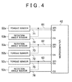
- the main torque sensor 52a and the backup rotation angle sensor 53b are connected to a SPI terminal T SPI1 of the microcomputer 42 via a SPI communication line (SPI bus) 61.
- the SPI communication line 61 has a branch line 61a that branches off from a branch point P1 that is set in an intermediate portion of the SPI communication line 61.
- the rotation angle sensor 53b is connected to the branch point P1 of the SPI communication line 61 via the branch line 61a.
- the two devices (the torque sensor 52a and the rotation angle sensor 53b) and the microcomputer 42 share the single SPI communication line 61 through which digital signals are transferred therebetween.
- the main rotation angle sensor 53a and the backup torque sensor 52b are connected to a SPI terminal T SPI2 of the microcomputer 42 via a SPI communication line 62. More specifically, the SPI communication line 62 has a branch line 62a that branches off from a branch point P2 that is set in an intermediate portion of the SPI communication line 62.
- the torque sensor 52b is connected to the branch point P2 of the SPI communication line 62 via the branch line 62a.
- the two devices (the rotation angle sensor 53a and the torque sensor 52b) and the microcomputer 42 share the single SPI communication line 62 through which digital signals are transferred therebetween.
- each of the SPI communication lines 61, 62 is made up of three communication lines that are an SCK (serial clock) line, a SDI (serial data input) line and a SDO (serial data output) line, the SPI communication lines 61, 62 are each indicated by a single continuous line in the drawings, for ease of explanation.
- the two torque sensors 52a, 52b are connected, via CS (Chip Select) signal lines 71, 72, to CS terminals T CS1 , T CS2 of the microcomputer 42, respectively.
- the two rotation angle sensors 53a, 53b are connected to CS terminals T CS3 , T CS4 of the microcomputer 42 via CS signal lines 73, 74, respectively.
- the CS signal lines 71 to 74 are used when the microcomputer 42 selects (or identifies) its communication target.
- the microcomputer 42 which is a master device in the SPI communication, selects each of the sensors, which are slave devices in the SPI communication, as its communication target, by activating a corresponding one of the CS terminal T CS1 to T CS4 to which the CS signal line 71 to 74 are connected, for example, turning the logic level thereof to a low level.
- the microcomputer 42 controls a selected one of the sensors via a corresponding one of the SPI communication lines 61, 62.
- the microcomputer 42 sends a clock signal to each sensor or takes in the detection results obtained by each sensor via a corresponding one of the SPI communication lines 61, 62.
- the torque sensor 52, the rotation angle sensor 53, the SPI communication lines 61, 62 and the microcomputer 42 described above constitute the actuator control apparatus.
- the microcomputer 42 takes in the detection results obtained by the torque sensor 52a and the rotation angle sensor 53b alternately via the SPI communication line 61 by alternately activating the two CS terminals T CS1 , T CS4 to which the torque sensor 52a and the rotation angle sensor 53b are connected, with a prescribed period.
- the microcomputer 42 takes in the detection results obtained by the rotation angle sensor 53a and the torque sensor 52b alternately via the SPI communication line 62 by alternately activating the two CS terminals T CS3 , T CS2 to which the rotation angle sensor 53a and the torque sensor 52b are connected, with a prescribed period.
- the period with which the CS terminals T CS1 , T CS4 of the SPI communication line 61 are switched is the same as the period with which the CS terminals T CS3 , T CS2 of the SPI communication line 62 are switched.
- the microcomputer 42 simultaneously takes in the detection results obtained by the torque sensor 52a and the rotation angle sensor 53a, and then simultaneously takes in the detection results obtained by the torque sensor 52b and the rotation angle sensor 53b.
- the microcomputer 42 executes malfunction detection on the torque sensor 52 on the basis of the detection results obtained by the torque sensor 52a and the torque sensor 52b.
- the microcomputer 42 executes malfunction detection on the rotation angle sensor 53 on the basis of the detection results obtained by the rotation angle sensor 53a and the rotation angle sensor 53b.
- a concrete detection method a known method is adopted as needed, for example, a method in which the detection results obtained by the two sensors are compared with each other, and if the difference therebetween falls outside an allowable range, it is determined that there is a malfunction.
- the microcomputer 42 When neither the torque sensor 52 nor the rotation angle sensor 53 malfunctions, the microcomputer 42 generates a motor drive signal on the basis of the detection results obtained by the main torque sensor 52a and the main rotation angle sensor 53a.
- the microcomputer 42 is capable of quickly and accurately generating the motor drive signal based on the detection results obtained by the torque sensor 52a and the rotation angle sensor 53a that are simultaneously taken into the microcomputer 42.
- the microcomputer 42 when the microcomputer 42 generates a motor drive signal based on the detection results obtained by the torque sensor 52a and the rotation angle sensor 53b, there occurs a difference between the timings at which the detection results obtained by the two sensors are respectively taken into the microcomputer 42, because the single SPI communication line is used for the communication. Similarly, when the microcomputer 42 generates a motor drive signal based on the detection results obtained by the torque sensor 52b and the rotation angle sensor 53a, there occurs a difference between the timings at which the detection results obtained by the two sensors are respectively taken into the microcomputer 42. Such a timing difference makes it difficult to generate an accurate motor drive signal.
- the microcomputer 42 is able to generate a motor drive signal only after taking in the detection result obtained by the other one of the torque sensor and the rotation angle sensor. This makes it difficult to promptly generate a motor drive signal.
- the microcomputer 42 When a malfunction is detected in the main torque sensor 52a or the rotation angle sensor 53a, the microcomputer 42 generates a motor drive signal based on the detection result obtained by the backup torque sensor 52b or the backup rotation angle sensor 53b instead of the detection result obtained by the sensor in which malfunction is detected.
- the torque sensor 52a and the rotation angle sensor 53b are connected to the single SPI terminal T SPI1 via the SPI communication line 61.
- the torque sensor 52b and the rotation angle sensor 53a are connected to the single SPI terminal T SPI2 via the SPI communication line 62. That is, the communication paths between the two sets of sensors, each set being made up of two kinds of sensors different from each other in function, and the microcomputer 42 form a duplexed system in which the two paths are completely independent of each other.
- the microcomputer 42 uses the remaining communication path to take in the detection results obtained by the torque sensor 52a and the rotation angle sensor 53b or the detection results obtained by the torque sensor 52b and the rotation angle sensor 53a.
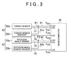
- the torque sensors 52a, 52b, the rotation angle sensors 53a, 53b and the microcomputer 42 may be connected to each other in the following method. As illustrated in FIG. 3 , the two torque sensors 52a, 52b are connected to the single SPI terminal T SPI1 via the single SPI communication line 61. Similarly, the two rotation angle sensors 53a, 53b are connected to the single SPI terminal T SPI2 via the single SPI communication line 62. With this configuration as well, if one of the two torque sensors 52a, 52b malfunctions or one of the two rotation angle sensors 53a, 53b malfunctions, the microcomputer 42 uses the other one of the torque sensors or the other one of the rotation angle sensors to generate a motor drive signal.
- the microcomputer 42 is able to take in only one of the steering torque ⁇ and the rotation angle ⁇ . This makes it difficult to generate an appropriate motor drive signal.
- the connection method described above with reference to FIG. 2 does not cause such a problem.
Landscapes
- Engineering & Computer Science (AREA)
- Mechanical Engineering (AREA)
- Chemical & Material Sciences (AREA)
- Combustion & Propulsion (AREA)
- Transportation (AREA)
- Power Steering Mechanism (AREA)
- Steering Control In Accordance With Driving Conditions (AREA)
- General Engineering & Computer Science (AREA)
- Safety Devices In Control Systems (AREA)
Applications Claiming Priority (1)
| Application Number | Priority Date | Filing Date | Title |
|---|---|---|---|
| JP2013117868A JP6136595B2 (ja) | 2013-06-04 | 2013-06-04 | アクチュエータ制御装置 |
Publications (3)
| Publication Number | Publication Date |
|---|---|
| EP2810853A2 true EP2810853A2 (de) | 2014-12-10 |
| EP2810853A3 EP2810853A3 (de) | 2017-02-22 |
| EP2810853B1 EP2810853B1 (de) | 2019-07-24 |
Family
ID=50932968
Family Applications (1)
| Application Number | Title | Priority Date | Filing Date |
|---|---|---|---|
| EP14170759.6A Active EP2810853B1 (de) | 2013-06-04 | 2014-06-02 | Aktuatorsteuervorrichtung |
Country Status (4)
| Country | Link |
|---|---|
| US (1) | US9043089B2 (de) |
| EP (1) | EP2810853B1 (de) |
| JP (1) | JP6136595B2 (de) |
| CN (1) | CN104210543B (de) |
Cited By (2)
| Publication number | Priority date | Publication date | Assignee | Title |
|---|---|---|---|---|
| WO2019042536A1 (en) * | 2017-08-30 | 2019-03-07 | Thyssenkrupp Presta Ag | MULTICANAL ECU ARCHITECTURE FOR EPS |
| GB2606222A (en) * | 2021-04-30 | 2022-11-02 | Jaguar Land Rover Ltd | A control system |
Families Citing this family (19)
| Publication number | Priority date | Publication date | Assignee | Title |
|---|---|---|---|---|
| US9365238B2 (en) * | 2014-01-17 | 2016-06-14 | Nsk Ltd. | Electric power steering apparatus |
| US20150363714A1 (en) * | 2014-06-17 | 2015-12-17 | Entic, Llc | Business intelligence and analytics of energy consuming systems |
| JP6679861B2 (ja) * | 2015-09-15 | 2020-04-15 | 株式会社デンソー | センサ装置、および、これを用いた電動パワーステアリング装置 |
| JP2017081387A (ja) * | 2015-10-27 | 2017-05-18 | Kyb株式会社 | センサ装置及び電動パワーステアリング装置 |
| JP6642278B2 (ja) * | 2016-05-27 | 2020-02-05 | 株式会社デンソー | 回転電機制御装置、および、これを用いた電動パワーステアリング装置 |
| JP6661483B2 (ja) * | 2016-07-04 | 2020-03-11 | クノールブレムゼステアリングシステムジャパン株式会社 | ステアリング装置用アクチュエータ |
| WO2018008628A1 (ja) * | 2016-07-05 | 2018-01-11 | 日本精工株式会社 | 検出装置及び電動パワーステアリング装置 |
| JP6714088B2 (ja) * | 2016-09-15 | 2020-06-24 | 日立オートモティブシステムズ株式会社 | 車両搭載機器のアクチュエータ及びパワーステアリング装置 |
| JP6770885B2 (ja) * | 2016-12-14 | 2020-10-21 | 株式会社ジェイテクト | 車両制御装置 |
| KR20190028842A (ko) * | 2017-09-11 | 2019-03-20 | 주식회사 만도 | 페일-세이프 전동식 파워 스티어링 장치 및 방법 |
| JP6907857B2 (ja) * | 2017-09-22 | 2021-07-21 | 株式会社アイシン | クラッチ制御装置 |
| JP2019091868A (ja) * | 2017-11-17 | 2019-06-13 | Kyb株式会社 | 制御装置および鉄道車両用制振装置 |
| KR102111303B1 (ko) * | 2018-12-06 | 2020-06-04 | 주식회사 만도 | 조향 장치 및 조향 제어 방법 |
| JP7315364B2 (ja) * | 2019-04-17 | 2023-07-26 | トヨタ自動車株式会社 | 操舵制御システム |
| JP7375357B2 (ja) * | 2019-07-30 | 2023-11-08 | マツダ株式会社 | 車両制御システム |
| JP7284690B2 (ja) * | 2019-11-11 | 2023-05-31 | 株式会社デンソー | モータ駆動システム |
| JP7380294B2 (ja) * | 2020-02-14 | 2023-11-15 | マツダ株式会社 | 移動体の制御システム |
| CN115411764B (zh) * | 2021-05-27 | 2025-03-25 | 华为数字能源技术有限公司 | 一种储能系统、物理位置识别方法及光伏发电系统 |
| CN113954957A (zh) * | 2021-11-22 | 2022-01-21 | 中国第一汽车股份有限公司 | 扭矩传感器冗余控制方法、装置、线控转向系统及车辆 |
Citations (1)
| Publication number | Priority date | Publication date | Assignee | Title |
|---|---|---|---|---|
| JP2000185657A (ja) | 1998-12-22 | 2000-07-04 | Kayaba Ind Co Ltd | 電動式パワーステアリング装置 |
Family Cites Families (24)
| Publication number | Priority date | Publication date | Assignee | Title |
|---|---|---|---|---|
| JPS6382875A (ja) * | 1986-09-29 | 1988-04-13 | Hitachi Ltd | 電動式パワ−ステアリング装置 |
| JP2577902B2 (ja) * | 1987-02-27 | 1997-02-05 | 富士重工業株式会社 | 4輪駆動車のフエイルセ−フ装置 |
| JPH0725278B2 (ja) * | 1988-08-31 | 1995-03-22 | 日産自動車株式会社 | 四輪駆動車の駆動力配分制御装置 |
| EP0556991B1 (de) * | 1992-02-19 | 1996-10-16 | Namco Controls Corporation | Sensorverbindungssystem |
| US20040026158A1 (en) * | 2000-03-27 | 2004-02-12 | Peter Rieth | Vehicle system and axle guide module for a vehicle steering system |
| JP4055519B2 (ja) * | 2002-08-30 | 2008-03-05 | 株式会社ジェイテクト | 車両用操舵装置 |
| JP3847702B2 (ja) * | 2002-12-02 | 2006-11-22 | 株式会社ジェイテクト | 車両の操舵制御装置 |
| JP3867682B2 (ja) * | 2003-05-29 | 2007-01-10 | 日産自動車株式会社 | 車両用操舵装置 |
| JP4188786B2 (ja) * | 2003-09-18 | 2008-11-26 | 株式会社日立製作所 | パワーステアリング装置 |
| DE102004044729A1 (de) * | 2003-09-18 | 2005-04-21 | Hitachi Unisia Automotive Ltd | Hilfskraftlenkungssystem |
| JP4506509B2 (ja) * | 2005-03-01 | 2010-07-21 | 日産自動車株式会社 | 操舵制御装置 |
| US7664584B2 (en) * | 2005-03-01 | 2010-02-16 | Nissan Motor Co., Ltd. | Steering control system |
| JP4794310B2 (ja) * | 2006-02-08 | 2011-10-19 | 士郎 神戸 | 計測信号のためのusb変換器 |
| DE102007024737A1 (de) * | 2007-05-25 | 2008-11-27 | Robert Bosch Gmbh | Datenübertragungsverfahren zwischen Master- und Slave-Einrichtungen |
| JP2010143241A (ja) * | 2008-12-16 | 2010-07-01 | Hitachi Automotive Systems Ltd | 操舵制御装置 |
| DE102009027020A1 (de) * | 2009-06-18 | 2010-12-23 | Robert Bosch Gmbh | Verbindungselement zum Anschluss einer Datenliefereinheit an einen Verbindungsstrang |
| US8723525B2 (en) * | 2009-07-06 | 2014-05-13 | Qualcomm Incorporated | Sensor in battery |
| JP5338544B2 (ja) * | 2009-07-28 | 2013-11-13 | 株式会社ジェイテクト | 電動パワーステアリング装置 |
| JP5531896B2 (ja) * | 2010-02-04 | 2014-06-25 | 日産自動車株式会社 | 電動油圧装置および電動油圧装置の作動油温度制御方法 |
| JP5086385B2 (ja) * | 2010-03-08 | 2012-11-28 | 日立オートモティブシステムズ株式会社 | 電動パワーステアリング制御装置 |
| US20110294096A1 (en) * | 2010-05-26 | 2011-12-01 | The Procter & Gamble Company | Acoustic Monitoring of Oral Care Devices |
| TW201305978A (zh) * | 2011-07-29 | 2013-02-01 | Liang-Tse Lin | 資料儲存系統及其操作方法 |
| TW201350374A (zh) * | 2012-06-07 | 2013-12-16 | Automotive Res & Testing Ct | 激發式轉向感測裝置及其感測方法 |
| CN103010299B (zh) * | 2012-12-14 | 2015-09-23 | 奇瑞汽车股份有限公司 | 汽车电动助力转向系统 |
-
2013
- 2013-06-04 JP JP2013117868A patent/JP6136595B2/ja active Active
-
2014
- 2014-05-29 US US14/290,061 patent/US9043089B2/en active Active
- 2014-05-30 CN CN201410240785.XA patent/CN104210543B/zh active Active
- 2014-06-02 EP EP14170759.6A patent/EP2810853B1/de active Active
Patent Citations (1)
| Publication number | Priority date | Publication date | Assignee | Title |
|---|---|---|---|---|
| JP2000185657A (ja) | 1998-12-22 | 2000-07-04 | Kayaba Ind Co Ltd | 電動式パワーステアリング装置 |
Cited By (5)
| Publication number | Priority date | Publication date | Assignee | Title |
|---|---|---|---|---|
| WO2019042536A1 (en) * | 2017-08-30 | 2019-03-07 | Thyssenkrupp Presta Ag | MULTICANAL ECU ARCHITECTURE FOR EPS |
| US11654957B2 (en) | 2017-08-30 | 2023-05-23 | Thyssenkrupp Presta Ag | Multichannel electronic control unit architecture for electromechanical power steering systems |
| GB2606222A (en) * | 2021-04-30 | 2022-11-02 | Jaguar Land Rover Ltd | A control system |
| WO2022229451A1 (en) * | 2021-04-30 | 2022-11-03 | Jaguar Land Rover Limited | A control system |
| GB2606222B (en) * | 2021-04-30 | 2023-09-27 | Jaguar Land Rover Ltd | A control system |
Also Published As
| Publication number | Publication date |
|---|---|
| US20140358375A1 (en) | 2014-12-04 |
| JP2014234101A (ja) | 2014-12-15 |
| CN104210543B (zh) | 2018-04-03 |
| JP6136595B2 (ja) | 2017-05-31 |
| CN104210543A (zh) | 2014-12-17 |
| EP2810853A3 (de) | 2017-02-22 |
| EP2810853B1 (de) | 2019-07-24 |
| US9043089B2 (en) | 2015-05-26 |
Similar Documents
| Publication | Publication Date | Title |
|---|---|---|
| EP2810853B1 (de) | Aktuatorsteuervorrichtung | |
| US11084523B2 (en) | Vehicle-mounted device actuator and power steering device | |
| US11958546B2 (en) | Steering control device and steering assist system including same | |
| CN108137088B (zh) | 用于运行机动车的转向系统的方法 | |
| US10322748B2 (en) | Motor controller and steering device | |
| EP2586679B1 (de) | Steuervorrichtung für fahrzeugreise | |
| CN111699125B (zh) | 为包括有冗余设计的控制装置的机动车辆的机电转向系统提供转向辅助的方法 | |
| CN106029471B (zh) | 动力转向装置及动力转向装置的控制装置 | |
| CN112351933A (zh) | 具有冗余配置的控制单元的机动车辆转向系统 | |
| EP3196096B1 (de) | Elektrische servolenkvorrichtung | |
| CN111130416B (zh) | 电机控制装置以及电机控制方法 | |
| US11554805B2 (en) | Vehicle control apparatus | |
| EP3369644A1 (de) | Sensorvorrichtung und elektrische servolenkung | |
| US10538265B2 (en) | Rotary electric device control device, and electric power steering device using the same | |
| CN113120071A (zh) | 电动助力转向控制系统 | |
| US11560172B2 (en) | Motor control device | |
| JP4483522B2 (ja) | 電動パワーステアリング装置及び電力供給システム | |
| EP3676157B1 (de) | Mehrkanalige ecu-architektur für eine elektrische servolenkung | |
| JP2009179185A (ja) | ステアバイワイヤシステムの診断装置およびステアバイワイヤシステムの診断方法 | |
| JP5092509B2 (ja) | 電動パワーステアリング装置 | |
| JP2004256018A (ja) | 動力操舵システム | |
| KR102874164B1 (ko) | 조향 제어 장치 | |
| JP2011225176A (ja) | 車両用操舵装置 | |
| JP2014117064A (ja) | モータ制御装置 |
Legal Events
| Date | Code | Title | Description |
|---|---|---|---|
| PUAI | Public reference made under article 153(3) epc to a published international application that has entered the european phase |
Free format text: ORIGINAL CODE: 0009012 |
|
| 17P | Request for examination filed |
Effective date: 20140602 |
|
| AK | Designated contracting states |
Kind code of ref document: A2 Designated state(s): AL AT BE BG CH CY CZ DE DK EE ES FI FR GB GR HR HU IE IS IT LI LT LU LV MC MK MT NL NO PL PT RO RS SE SI SK SM TR |
|
| AX | Request for extension of the european patent |
Extension state: BA ME |
|
| RIC1 | Information provided on ipc code assigned before grant |
Ipc: B60W 50/029 20120101ALI20160817BHEP Ipc: B62D 5/04 20060101AFI20160817BHEP |
|
| STAA | Information on the status of an ep patent application or granted ep patent |
Free format text: STATUS: REQUEST FOR EXAMINATION WAS MADE |
|
| R17P | Request for examination filed (corrected) |
Effective date: 20161028 |
|
| PUAL | Search report despatched |
Free format text: ORIGINAL CODE: 0009013 |
|
| AK | Designated contracting states |
Kind code of ref document: A3 Designated state(s): AL AT BE BG CH CY CZ DE DK EE ES FI FR GB GR HR HU IE IS IT LI LT LU LV MC MK MT NL NO PL PT RO RS SE SI SK SM TR |
|
| AX | Request for extension of the european patent |
Extension state: BA ME |
|
| RIC1 | Information provided on ipc code assigned before grant |
Ipc: B60W 50/029 20120101ALI20170118BHEP Ipc: B62D 5/04 20060101AFI20170118BHEP |
|
| RBV | Designated contracting states (corrected) |
Designated state(s): AL AT BE BG CH CY CZ DE DK EE ES FI FR GB GR HR HU IE IS IT LI LT LU LV MC MK MT NL NO PL PT RO RS SE SI SK SM TR |
|
| STAA | Information on the status of an ep patent application or granted ep patent |
Free format text: STATUS: EXAMINATION IS IN PROGRESS |
|
| 17Q | First examination report despatched |
Effective date: 20180525 |
|
| GRAP | Despatch of communication of intention to grant a patent |
Free format text: ORIGINAL CODE: EPIDOSNIGR1 |
|
| STAA | Information on the status of an ep patent application or granted ep patent |
Free format text: STATUS: GRANT OF PATENT IS INTENDED |
|
| INTG | Intention to grant announced |
Effective date: 20190116 |
|
| RIN1 | Information on inventor provided before grant (corrected) |
Inventor name: MATSUMOTO, TSUTOMU Inventor name: SAKAI, ATSUO Inventor name: SAKAI, KAZUYA Inventor name: ADACHI, TAKEHIDE Inventor name: KOZUKA, KENICHI |
|
| GRAS | Grant fee paid |
Free format text: ORIGINAL CODE: EPIDOSNIGR3 |
|
| GRAA | (expected) grant |
Free format text: ORIGINAL CODE: 0009210 |
|
| STAA | Information on the status of an ep patent application or granted ep patent |
Free format text: STATUS: THE PATENT HAS BEEN GRANTED |
|
| AK | Designated contracting states |
Kind code of ref document: B1 Designated state(s): AL AT BE BG CH CY CZ DE DK EE ES FI FR GB GR HR HU IE IS IT LI LT LU LV MC MK MT NL NO PL PT RO RS SE SI SK SM TR |
|
| REG | Reference to a national code |
Ref country code: GB Ref legal event code: FG4D |
|
| REG | Reference to a national code |
Ref country code: CH Ref legal event code: EP |
|
| REG | Reference to a national code |
Ref country code: DE Ref legal event code: R096 Ref document number: 602014050364 Country of ref document: DE |
|
| REG | Reference to a national code |
Ref country code: AT Ref legal event code: REF Ref document number: 1157823 Country of ref document: AT Kind code of ref document: T Effective date: 20190815 |
|
| REG | Reference to a national code |
Ref country code: IE Ref legal event code: FG4D |
|
| REG | Reference to a national code |
Ref country code: NL Ref legal event code: MP Effective date: 20190724 |
|
| REG | Reference to a national code |
Ref country code: LT Ref legal event code: MG4D |
|
| REG | Reference to a national code |
Ref country code: AT Ref legal event code: MK05 Ref document number: 1157823 Country of ref document: AT Kind code of ref document: T Effective date: 20190724 |
|
| PG25 | Lapsed in a contracting state [announced via postgrant information from national office to epo] |
Ref country code: FI Free format text: LAPSE BECAUSE OF FAILURE TO SUBMIT A TRANSLATION OF THE DESCRIPTION OR TO PAY THE FEE WITHIN THE PRESCRIBED TIME-LIMIT Effective date: 20190724 Ref country code: HR Free format text: LAPSE BECAUSE OF FAILURE TO SUBMIT A TRANSLATION OF THE DESCRIPTION OR TO PAY THE FEE WITHIN THE PRESCRIBED TIME-LIMIT Effective date: 20190724 Ref country code: LT Free format text: LAPSE BECAUSE OF FAILURE TO SUBMIT A TRANSLATION OF THE DESCRIPTION OR TO PAY THE FEE WITHIN THE PRESCRIBED TIME-LIMIT Effective date: 20190724 Ref country code: NO Free format text: LAPSE BECAUSE OF FAILURE TO SUBMIT A TRANSLATION OF THE DESCRIPTION OR TO PAY THE FEE WITHIN THE PRESCRIBED TIME-LIMIT Effective date: 20191024 Ref country code: SE Free format text: LAPSE BECAUSE OF FAILURE TO SUBMIT A TRANSLATION OF THE DESCRIPTION OR TO PAY THE FEE WITHIN THE PRESCRIBED TIME-LIMIT Effective date: 20190724 Ref country code: BG Free format text: LAPSE BECAUSE OF FAILURE TO SUBMIT A TRANSLATION OF THE DESCRIPTION OR TO PAY THE FEE WITHIN THE PRESCRIBED TIME-LIMIT Effective date: 20191024 Ref country code: NL Free format text: LAPSE BECAUSE OF FAILURE TO SUBMIT A TRANSLATION OF THE DESCRIPTION OR TO PAY THE FEE WITHIN THE PRESCRIBED TIME-LIMIT Effective date: 20190724 Ref country code: PT Free format text: LAPSE BECAUSE OF FAILURE TO SUBMIT A TRANSLATION OF THE DESCRIPTION OR TO PAY THE FEE WITHIN THE PRESCRIBED TIME-LIMIT Effective date: 20191125 Ref country code: AT Free format text: LAPSE BECAUSE OF FAILURE TO SUBMIT A TRANSLATION OF THE DESCRIPTION OR TO PAY THE FEE WITHIN THE PRESCRIBED TIME-LIMIT Effective date: 20190724 |
|
| PG25 | Lapsed in a contracting state [announced via postgrant information from national office to epo] |
Ref country code: ES Free format text: LAPSE BECAUSE OF FAILURE TO SUBMIT A TRANSLATION OF THE DESCRIPTION OR TO PAY THE FEE WITHIN THE PRESCRIBED TIME-LIMIT Effective date: 20190724 Ref country code: AL Free format text: LAPSE BECAUSE OF FAILURE TO SUBMIT A TRANSLATION OF THE DESCRIPTION OR TO PAY THE FEE WITHIN THE PRESCRIBED TIME-LIMIT Effective date: 20190724 Ref country code: LV Free format text: LAPSE BECAUSE OF FAILURE TO SUBMIT A TRANSLATION OF THE DESCRIPTION OR TO PAY THE FEE WITHIN THE PRESCRIBED TIME-LIMIT Effective date: 20190724 Ref country code: IS Free format text: LAPSE BECAUSE OF FAILURE TO SUBMIT A TRANSLATION OF THE DESCRIPTION OR TO PAY THE FEE WITHIN THE PRESCRIBED TIME-LIMIT Effective date: 20191124 Ref country code: RS Free format text: LAPSE BECAUSE OF FAILURE TO SUBMIT A TRANSLATION OF THE DESCRIPTION OR TO PAY THE FEE WITHIN THE PRESCRIBED TIME-LIMIT Effective date: 20190724 Ref country code: GR Free format text: LAPSE BECAUSE OF FAILURE TO SUBMIT A TRANSLATION OF THE DESCRIPTION OR TO PAY THE FEE WITHIN THE PRESCRIBED TIME-LIMIT Effective date: 20191025 |
|
| PG25 | Lapsed in a contracting state [announced via postgrant information from national office to epo] |
Ref country code: TR Free format text: LAPSE BECAUSE OF FAILURE TO SUBMIT A TRANSLATION OF THE DESCRIPTION OR TO PAY THE FEE WITHIN THE PRESCRIBED TIME-LIMIT Effective date: 20190724 |
|
| PG25 | Lapsed in a contracting state [announced via postgrant information from national office to epo] |
Ref country code: EE Free format text: LAPSE BECAUSE OF FAILURE TO SUBMIT A TRANSLATION OF THE DESCRIPTION OR TO PAY THE FEE WITHIN THE PRESCRIBED TIME-LIMIT Effective date: 20190724 Ref country code: DK Free format text: LAPSE BECAUSE OF FAILURE TO SUBMIT A TRANSLATION OF THE DESCRIPTION OR TO PAY THE FEE WITHIN THE PRESCRIBED TIME-LIMIT Effective date: 20190724 Ref country code: PL Free format text: LAPSE BECAUSE OF FAILURE TO SUBMIT A TRANSLATION OF THE DESCRIPTION OR TO PAY THE FEE WITHIN THE PRESCRIBED TIME-LIMIT Effective date: 20190724 Ref country code: IT Free format text: LAPSE BECAUSE OF FAILURE TO SUBMIT A TRANSLATION OF THE DESCRIPTION OR TO PAY THE FEE WITHIN THE PRESCRIBED TIME-LIMIT Effective date: 20190724 Ref country code: RO Free format text: LAPSE BECAUSE OF FAILURE TO SUBMIT A TRANSLATION OF THE DESCRIPTION OR TO PAY THE FEE WITHIN THE PRESCRIBED TIME-LIMIT Effective date: 20190724 |
|
| PG25 | Lapsed in a contracting state [announced via postgrant information from national office to epo] |
Ref country code: SK Free format text: LAPSE BECAUSE OF FAILURE TO SUBMIT A TRANSLATION OF THE DESCRIPTION OR TO PAY THE FEE WITHIN THE PRESCRIBED TIME-LIMIT Effective date: 20190724 Ref country code: SM Free format text: LAPSE BECAUSE OF FAILURE TO SUBMIT A TRANSLATION OF THE DESCRIPTION OR TO PAY THE FEE WITHIN THE PRESCRIBED TIME-LIMIT Effective date: 20190724 Ref country code: IS Free format text: LAPSE BECAUSE OF FAILURE TO SUBMIT A TRANSLATION OF THE DESCRIPTION OR TO PAY THE FEE WITHIN THE PRESCRIBED TIME-LIMIT Effective date: 20200224 Ref country code: CZ Free format text: LAPSE BECAUSE OF FAILURE TO SUBMIT A TRANSLATION OF THE DESCRIPTION OR TO PAY THE FEE WITHIN THE PRESCRIBED TIME-LIMIT Effective date: 20190724 |
|
| REG | Reference to a national code |
Ref country code: DE Ref legal event code: R097 Ref document number: 602014050364 Country of ref document: DE |
|
| PLBE | No opposition filed within time limit |
Free format text: ORIGINAL CODE: 0009261 |
|
| STAA | Information on the status of an ep patent application or granted ep patent |
Free format text: STATUS: NO OPPOSITION FILED WITHIN TIME LIMIT |
|
| PG2D | Information on lapse in contracting state deleted |
Ref country code: IS |
|
| 26N | No opposition filed |
Effective date: 20200603 |
|
| PG25 | Lapsed in a contracting state [announced via postgrant information from national office to epo] |
Ref country code: SI Free format text: LAPSE BECAUSE OF FAILURE TO SUBMIT A TRANSLATION OF THE DESCRIPTION OR TO PAY THE FEE WITHIN THE PRESCRIBED TIME-LIMIT Effective date: 20190724 |
|
| PG25 | Lapsed in a contracting state [announced via postgrant information from national office to epo] |
Ref country code: MC Free format text: LAPSE BECAUSE OF FAILURE TO SUBMIT A TRANSLATION OF THE DESCRIPTION OR TO PAY THE FEE WITHIN THE PRESCRIBED TIME-LIMIT Effective date: 20190724 |
|
| REG | Reference to a national code |
Ref country code: CH Ref legal event code: PL |
|
| GBPC | Gb: european patent ceased through non-payment of renewal fee |
Effective date: 20200602 |
|
| PG25 | Lapsed in a contracting state [announced via postgrant information from national office to epo] |
Ref country code: LU Free format text: LAPSE BECAUSE OF NON-PAYMENT OF DUE FEES Effective date: 20200602 |
|
| REG | Reference to a national code |
Ref country code: BE Ref legal event code: MM Effective date: 20200630 |
|
| PG25 | Lapsed in a contracting state [announced via postgrant information from national office to epo] |
Ref country code: CH Free format text: LAPSE BECAUSE OF NON-PAYMENT OF DUE FEES Effective date: 20200630 Ref country code: IE Free format text: LAPSE BECAUSE OF NON-PAYMENT OF DUE FEES Effective date: 20200602 Ref country code: LI Free format text: LAPSE BECAUSE OF NON-PAYMENT OF DUE FEES Effective date: 20200630 Ref country code: GB Free format text: LAPSE BECAUSE OF NON-PAYMENT OF DUE FEES Effective date: 20200602 |
|
| PG25 | Lapsed in a contracting state [announced via postgrant information from national office to epo] |
Ref country code: BE Free format text: LAPSE BECAUSE OF NON-PAYMENT OF DUE FEES Effective date: 20200630 |
|
| PG25 | Lapsed in a contracting state [announced via postgrant information from national office to epo] |
Ref country code: MT Free format text: LAPSE BECAUSE OF FAILURE TO SUBMIT A TRANSLATION OF THE DESCRIPTION OR TO PAY THE FEE WITHIN THE PRESCRIBED TIME-LIMIT Effective date: 20190724 Ref country code: CY Free format text: LAPSE BECAUSE OF FAILURE TO SUBMIT A TRANSLATION OF THE DESCRIPTION OR TO PAY THE FEE WITHIN THE PRESCRIBED TIME-LIMIT Effective date: 20190724 |
|
| PG25 | Lapsed in a contracting state [announced via postgrant information from national office to epo] |
Ref country code: MK Free format text: LAPSE BECAUSE OF FAILURE TO SUBMIT A TRANSLATION OF THE DESCRIPTION OR TO PAY THE FEE WITHIN THE PRESCRIBED TIME-LIMIT Effective date: 20190724 |
|
| PGFP | Annual fee paid to national office [announced via postgrant information from national office to epo] |
Ref country code: DE Payment date: 20250429 Year of fee payment: 12 |
|
| PGFP | Annual fee paid to national office [announced via postgrant information from national office to epo] |
Ref country code: FR Payment date: 20250508 Year of fee payment: 12 |