EP2810876B1 - Viermodulares Antriebssystem für Orbit- und Fluglageregelung eines Satelliten - Google Patents
Viermodulares Antriebssystem für Orbit- und Fluglageregelung eines Satelliten Download PDFInfo
- Publication number
- EP2810876B1 EP2810876B1 EP14171563.1A EP14171563A EP2810876B1 EP 2810876 B1 EP2810876 B1 EP 2810876B1 EP 14171563 A EP14171563 A EP 14171563A EP 2810876 B1 EP2810876 B1 EP 2810876B1
- Authority
- EP
- European Patent Office
- Prior art keywords
- thrust
- satellite
- axis
- propulsion
- modules
- Prior art date
- Legal status (The legal status is an assumption and is not a legal conclusion. Google has not performed a legal analysis and makes no representation as to the accuracy of the status listed.)
- Active
Links
Images


Classifications
-
- B—PERFORMING OPERATIONS; TRANSPORTING
- B64—AIRCRAFT; AVIATION; COSMONAUTICS
- B64G—COSMONAUTICS; VEHICLES OR EQUIPMENT THEREFOR
- B64G1/00—Cosmonautic vehicles
- B64G1/22—Parts of, or equipment specially adapted for fitting in or to, cosmonautic vehicles
- B64G1/24—Guiding or controlling apparatus, e.g. for attitude control
- B64G1/242—Orbits and trajectories
- B64G1/2425—Geosynchronous orbits
-
- B—PERFORMING OPERATIONS; TRANSPORTING
- B64—AIRCRAFT; AVIATION; COSMONAUTICS
- B64G—COSMONAUTICS; VEHICLES OR EQUIPMENT THEREFOR
- B64G1/00—Cosmonautic vehicles
- B64G1/22—Parts of, or equipment specially adapted for fitting in or to, cosmonautic vehicles
- B64G1/24—Guiding or controlling apparatus, e.g. for attitude control
- B64G1/242—Orbits and trajectories
- B64G1/2427—Transfer orbits
-
- B—PERFORMING OPERATIONS; TRANSPORTING
- B64—AIRCRAFT; AVIATION; COSMONAUTICS
- B64G—COSMONAUTICS; VEHICLES OR EQUIPMENT THEREFOR
- B64G1/00—Cosmonautic vehicles
- B64G1/22—Parts of, or equipment specially adapted for fitting in or to, cosmonautic vehicles
- B64G1/24—Guiding or controlling apparatus, e.g. for attitude control
- B64G1/26—Guiding or controlling apparatus, e.g. for attitude control using jets
- B64G1/262—Guiding or controlling apparatus, e.g. for attitude control using jets having adjustable angles, e.g. gimbaled thrusters
-
- B—PERFORMING OPERATIONS; TRANSPORTING
- B64—AIRCRAFT; AVIATION; COSMONAUTICS
- B64G—COSMONAUTICS; VEHICLES OR EQUIPMENT THEREFOR
- B64G1/00—Cosmonautic vehicles
- B64G1/10—Artificial satellites; Systems of such satellites; Interplanetary vehicles
- B64G1/1007—Communications satellites
-
- B—PERFORMING OPERATIONS; TRANSPORTING
- B64—AIRCRAFT; AVIATION; COSMONAUTICS
- B64G—COSMONAUTICS; VEHICLES OR EQUIPMENT THEREFOR
- B64G1/00—Cosmonautic vehicles
- B64G1/10—Artificial satellites; Systems of such satellites; Interplanetary vehicles
- B64G1/1014—Navigation satellites
-
- B—PERFORMING OPERATIONS; TRANSPORTING
- B64—AIRCRAFT; AVIATION; COSMONAUTICS
- B64G—COSMONAUTICS; VEHICLES OR EQUIPMENT THEREFOR
- B64G1/00—Cosmonautic vehicles
- B64G1/10—Artificial satellites; Systems of such satellites; Interplanetary vehicles
- B64G1/1021—Earth observation satellites
Definitions
- the present invention relates to the field of orbit control systems and satellite attitude control, and more particularly the architecture of onboard propulsion systems for the orbit control of geostationary telecommunications satellites.
- the position and orientation of the satellite in orbit should be controlled.
- control systems are implemented to maintain on the one hand the orientation of the satellite relative to the earth is the attitude control, and secondly its position in orbit with respect to a desired ideal position is the orbit control.
- the orbit control seeks to limit the inclination with respect to the equatorial plane, to limit the eccentricity of the orbit, and to limit the drift of the longitudinal position of the satellite relative to Earth.
- thrusters are positioned at various locations on the satellite to correct the trajectory at more or less close interval by applying a force on the satellite.
- a satellite is put into orbit by the combination of a launch vehicle and its own propulsion systems.
- the launcher transports and releases the satellite on a first so-called transfer orbit, whose perigee is generally low; once on this first orbit, a satellite propulsion system takes over to transport the satellite to its final orbit.
- this transfer is carried out by means of a main PSP satellite propellant consuming a chemical fuel of the ergol or propellant type, delivering a high power thrust enabling the final orbit to be reached quickly.
- propellant chemical propellants or electric thrusters can be used.
- an electric propellant of propellant type to plasma, or ion thruster
- xenon atoms are ionized by collision with electrons, creating xenon ions.
- the thrust is generated when the charged xenon ions are accelerated out of the thruster by an electromagnetic field.
- the effectiveness of the thruster, or its capacity to generate force by mass ejection, also called specific impulse is significantly greater than that of chemical thrusters.
- an orbit control system seeks to control the position of the satellite through six orbital parameters.
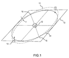
- the figure 1 represents a geostationary satellite 10 in orbit 11 around the earth 12.
- the orbit 11 is inclined at an angle ⁇ with respect to the equatorial plane 13 which contains the ideal geostationary orbit 14.
- the satellite orbit 11 intersects the equatorial plane 13 at two points 15 and 16, commonly referred to as orbital nodes.
- Orbit control involves quantifying these orbital parameters and performing the necessary operations using onboard propulsion systems, to maintain the satellite in a predefined area around an ideal position. For example, for a geostationary satellite, a drift window of plus or minus 0.1 °, representing a width of almost 150km, is assigned around a target position.
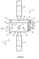
- a current architecture of a satellite 10, as represented on the figure 2 comprises a parallelepiped structure 20 on which are fixed various devices useful for controlling the satellite 10 and its mission.
- Telecommunications instruments 21 are installed on one side 22 whose orientation is maintained in the direction of the earth, commonly referred to as the earth face.
- the main satellite propeller PSP which provides in particular the thrust necessary for the transfer of the low orbit to the final orbit.
- two opposite lateral faces 24 and 25 commonly called North face and South face, because of their orientation relative to the equatorial plane, are positioned two sets of solar panels 26 and 27 for the supply of electrical energy of embedded systems.
- attitude control system capable of detecting and correcting orientation errors.
- the measurement of the orientation of the satellite can be carried out by means of a sensor assembly, comprising for example a sensor directed towards the earth, positioned on the ground face for a measurement on two axes, pitch and roll, with respect to ground and a set of 30 gyroscopes for detection of rotational speeds on three axes. From these measurements, corrections of orientation of the satellite around its center of gravity can be achieved, for example by means of a set of inertia wheels 31 or gyroscopic actuators.
- a satellite equipped with such a system for attitude control is said to be stabilized on three axes.
- Z an axis directed towards the earth, also called yaw axis
- Y an axis perpendicular to the orbit and oriented in the opposite direction to the kinetic moment of the orbit (towards the south for a geostationary), also called pitch axis
- X an axis forming with Y and Z a direct orthogonal reference, also called a rolling axis which is oriented according to the speed in the case of circular orbits.
- a first high power PSP propulsion to ensure the transfer between the initial earth orbit (after release of the launcher) and the final orbit , is positioned on the anti-earth face 23.
- a first set of thrusters comprising for example two thrusters 32 and 33 positioned on the north face and on the south face near the anti-earth face, is used to control the inclination.
- a second set of thrusters such as thrusters 34 and 35, positioned on the east and west faces, is used to control eccentricity and drift. It is also known that tilt control requires about five to ten times more fuel than control of eccentricity and drift. For this reason, the tilt control is generally performed by means of plasma propellant, more low fuel consumption, while the thrusters dedicated to the control of eccentricity and drift are most often chemical propellant.
- a 2500kg dry mass conventional satellite that can carry a payload of 900 kg comprises a main thruster, two plasma thrusters for tilting and eccentricity, and four propellant propellants for the engine. eccentricity and drift.
- 1700kg of propellant is required for the initial orbit transfer, and 220kg of Xenon is required to provide satellite orbit control for a mission duration of approximately 15 years.
- the cost and mass of current propulsion systems limit the ability to carry a high payload.
- the various onboard propellers actually include two propulsion engines positioned side by side, for reasons of safety and reliability of the mission.
- a thruster may consist of one or more propulsive engines forming a propulsion unit, and whose thrust which can be delivered is identical, in orientation or intensity.
- the Figures 3a, 3b and 3c illustrate the principle of orbit control for a satellite according to the state of the art.
- the structure 20 of satellite 10 is shown in side view, the east face being visible.
- the thruster 32 is connected to the north face of the structure 20 by means of a two-axis mechanism 40.
- the two-axis mechanism 40 allows the rotation of the thruster 32 relative to the structure 20 along a first axis parallel to the Y axis and a second axis parallel to the X axis.
- the two-axis mechanism 40 is a universal joint made by means of a first pivot link 41 with an axis parallel to the Y axis and a second pivot lading 42 with an axis parallel to the axis X.
- the center of mass of the satellite, located inside the parallelepipedal structure 20, is referenced CM.
- the orientation of the thruster 32 makes it possible to direct the thrust of the thruster towards the center of mass CM of the satellite.
- a technique known to those skilled in the art is to ignite the thruster 32 a first time near an orbital node, for example 15, then the thruster of the opposite side a second time to near the opposite orbital node, 16 in the example.
- the thrust of the first ignition of the thruster 32 oriented towards the center of mass CM, moves the satellite in a direction having a Z component and a Y component.
- a common satellite comprises four chemical propellant nozzles positioned on the east and west faces of the satellite.
- the thruster systems 32 and 33 are also useful for managing the momentum of attitude control systems, as illustrated in FIGS. Figures 3b and 3c .
- a thrust out of the center of mass CM - in a plane YZ on the figure 3b and out of the YZ plane on the figure 3c we generate a torque of rotation on the satellite - a couple of rolls on the figure 3b and a couple of pitch and yaw on the figure 3c .
- These two couples can be used to load or unload the flywheels along two axes.
- an inertia wheel when the rotational speed of an inertia wheel reaches its limit speed, it will seek to steer the thrust intentionally out of the center of mass CM so as to generate, in addition to the desired movement of the satellite, a torque to desaturate the flywheel, or more generally, the problem will be anticipated by reducing the kinetic momentum to desired values on the occasion of each maneuver.
- desired values can of course be zero, but also a judiciously defined value so as to anticipate the evolution of the kinetic moment between two maneuvers under the effect of the solar radiation pressure in particular.
- center of mass of the satellite varies during the life of the satellite, particularly because of the progressive consumption of onboard fuel.
- algorithms are implemented for the combined management of attitude control and orbit control, and to take into account the position of the center of mass CM throughout the life of the satellite.
- the invention aims to propose an alternative solution for the control of the orbit and the realization of the couples to be exercised on the satellite during the maneuvers by overcoming the implementation difficulties mentioned above.
- each of the two propulsion modules of each of the two sets of propulsion comprises a redundancy propellant disposed on the plate in the vicinity of said propellant, and so that its thrust axis is parallel to that of said thruster.
- At least one of the two propulsion modules of at least one of the two propulsion assemblies comprises a second motorized connection for rotation about an axis T perpendicular to both the V axis. and the propeller thrust axis of said propulsion module.
- the second motorized connection connects the first motorized link to the offset arm of said propulsion module. It is also envisaged that the second motorized connection connects the offset arm and the plate of said propulsion module. It is further envisaged that the second motorized link is connected to the plate by means of a second offset arm of said propulsion module. Finally, it is also envisaged that the second motorized link connects the first motorized link to the satellite.
- the invention also relates to a terrestrial orbiting satellite equipped with a propulsion system having the characteristics described above.
- the Figures 4a and 4b represent a first embodiment of the propulsion system respectively in the storage position and in the operative position.
- a satellite 10 in orbit 11 is stabilized on three axes of a reference trihedron connected to the satellite by means of an attitude control system.
- the reference trihedron comprises a Z axis oriented towards the earth, a Y axis perpendicular to the obite and oriented in the opposite direction to the kinetic momentum of the orbital rotation, and an X axis forming a direct orthogonal coordinate system with the Y and Z axes.
- the X axis is then oriented in the direction of the speed of the satellite in orbit 11 around the earth 12.
- the satellite 10 comprises a parallelepipedal structure 20, two faces 22 and 23, said face and face anti-earth, are perpendicular to the Z axis and respectively oriented towards the earth and towards a direction opposite to the earth, and two opposite opposite faces 24 and 25, said north face and south face, are perpendicular to the Y axis and respectively oriented north and south in the Earth's magnetic field.
- the description of the invention is based on the reference formed by the X, Y and Z axes and on a satellite whose structure 20 is parallelepiped.
- the invention is not limited in any way to a satellite whose structure 20 is parallelepiped, nor to a satellite stabilized on the three axes X, Y and Z. It extends generally to any satellite 10 in Earth orbit 11 having a kinetic momentum accumulation capacity, animated by a tangential displacement speed to the Earth's orbit 11.
- the axis of the speed is referenced V axis; it is confused with the X axis in the particular case represented in the figures of a satellite in circular orbit.
- the propulsion system comprises two sets of propulsion attached to the satellite, and facing one another relative to the plane of the orbit 11.
- the two sets of propulsion are arranged respectively on the north faces 24 and south 25.
- the Figures 4a, 4b and 5a represent a single propulsion assembly 100 attached to the satellite on the north face 24. It is understood however that the propulsion system according to the invention comprises two sets of propulsion facing each other relative to the plane of the orbit 11.
- the propulsion modules 50a and 50b therefore have an identical architecture, they differ in their location on the satellite.
- the two propulsion modules of each propulsion unit are connected to the satellite, on the north face 24, on both sides and substantially at equal distances from a plane P perpendicular to the axis V passing through the center of mass CM of the satellite.
- each propulsion module respectively 50a and 50b, also comprises a redundancy propellant, respectively 55a and 55b, disposed on the plate, respectively 53a and 53b, near the main thruster, respectively 54a and 54b.
- This redundancy thruster, respectively 55a and 55b, is oriented on the plate so that its axis of thrust is parallel to the thrust axis of said main thruster, respectively 54a and 54b.
- the main thruster and the redundancy thruster of each of the propulsion modules are positioned in line along the axis of the speed as shown in FIGS. Figures 4a and 4b . It is also envisaged to have the two thrusters redundant between the two main thrusters, and equidistant from the plane P previously defined.
- the propulsion system comprises two propulsion assemblies whose identical architecture comprises the components described above.
- each of two propulsion modules of the propulsion assembly 100 is disposed opposite to the plane of the orbit, an identical propulsion module of the second propulsion unit (not shown).
- the figure 4a represents the propulsion assembly 100 in a storage position adapted to launch the satellite.
- each of the two propulsion modules, respectively 50a and 50b is in the storage position; the offset arm, respectively 53a and 53b is held against the satellite, against the north face of the satellite structure in the figure.
- the propulsion system has a limited size. It is advantageous to orient the thrust axes of the thrusters of each of the propulsion modules so that, in the storage position, they are parallel to the axis Z.
- the storage position is adapted to the transfer of orbit, the simultaneous ignition of the thrusters of the two sets of propulsion generating a resulting thrust aligned with the Z axis. It is therefore envisaged to solicit the propulsion system, by simultaneous ignition of the main thrusters and / or redundancy of the system. propulsion, to achieve the orbit transfer, either in addition to the PSP thruster or in place of the PSP thruster.
- the thrusters are oriented on their plate so that, in the storage position, their thrust axes are not strictly parallel to the Z axis but are slightly inclined towards the plane of the orbit.
- the figure 4b represents the propulsion assembly 100 in an operational position adapted to the orbit control.
- the offset arm and the plate are moved by means of the motorized connection so that the plane parallel to the axis V containing the thrust axis of the propulsion unit of said propulsion module, passes close to the center of mass CM of the satellite.
- the simultaneous ignition of the thrusters 54a and 54b of the two propulsion modules 50a and 50b results in a thrust on the center of mass CM, having a significant component along the Y axis.
- CM center of mass
- the known systems which have thrusters near the anti-earth face generate a thrust presenting as a weak component along the Y axis. This results in a low efficiency of tilt control.
- the propulsion assembly according to the invention makes it possible, by the displacement of the remote propellers on the plate, and by means of the motorized connection fixed at a distance from the anti-earth face, to generate a thrust having a component along the Y axis. significantly larger. This results in a better efficiency of tilt control, the amount of fuel consumed unnecessarily by the component along the X axis is reduced. Typically, it is envisaged to position the motorized link 51a near the middle of the north face along the Z axis.
- a propulsion module too large, or positioned too close to the solar generators is likely to reduce the efficiency of solar generators by shading, during the transfer of orbit or during station keeping.
- the ignition of thrusters can cause erosion or contamination of equipment (antenna reflectors, solar generators) if they are placed too close to this equipment.
- the propulsion system also allows the control of the torque around three axes.
- the simultaneous ignition of the two thrusters slightly oriented out of the center of mass CM generates in addition to the speed increment of the satellite a rolling torque around the axis X.
- a differential ignition, in intensity or duration, of the two thrusters 54a and 54b generate in addition to the speed increment of the satellite a torque around a perpendicular axis T at a time the V axis and the thrust axes of the thrusters.
- the propulsion assembly 100 advantageously makes it possible to decouple the orientation of each of the two modules of propulsion 50a and 50 about their axis of rotation.
- a limited amplitude reorientation of each of the propulsion modules 50a and 50b by rotation in the opposite direction about their axis of rotation makes it possible to generate a torque around a third perpendicular axis. at both the T axis and the V axis.
- the present invention makes it possible, by means of a simple and inexpensive system, to provide both north-south inclination control and three-axis torque control.
- FIGS. 5a, 5b and 5c represent a second embodiment of the propulsion system in operational position.
- the figures represent only one propulsion unit, but the propulsion system according to this second embodiment comprises two propulsion units facing each other relative to the plane of the orbit.
- the propulsion assembly comprises two propulsion modules 50a and 50b having the same characteristics as previously described. These features are not repeated in detail here.
- This embodiment differs from the first embodiment by adding a degree of freedom in rotation to at least one propulsion module of a propulsion unit.
- a degree of freedom in rotation to one or more other propulsion modules, the same set of propulsion or the opposite set of propulsion, is also envisaged, in particular to improve the robustness of the propulsion system to possible failures.
- this propulsion module 50b comprises a second motorized connection 70b of rotation about an axis T perpendicular to both the axis V and the thrust axis of the propellant 54b of the propulsion module 50b.
- this second motorized link is directly connected to the first motorized link, or in other words the motorized link 51a can be likened to a two-axis link, of the cardan link type, for example.
- This embodiment is however not limiting of the present invention and it is also envisaged to arrange this second connection between the offset arm 52b and the plate 53b; or arranging the second link 70b between the offset arm 52b and a second offset arm itself connected to the plate 53b; or to arrange the second motorized link 70b between the first motorized link 51b and the satellite 10.
- the interest of this second embodiment is illustrated by the Figures 5b and 5c .
- the figure 5b represents the two propulsion modules 50a and 50b in operational position.
- the plane containing the thrust axes of the thrusters 54a and 54b of the two propulsion modules 50a and 50b passes through the center of mass CM of the satellite.
- the second motorized link 70b of the propulsion module 50b is in a centered position; the thrust axis being aligned on the Z axis (as is the case represented on the figure 5a ).
- the propulsion module is shown in the plane containing the thrust axes of the thrusters.
- This plane is perpendicular to the axis T of rotation of the second motorized connection 70b, it contains the axes of rotation R1a and R1b, the first motorized links 51a and 51b of the propulsion modules 50a and 50b.
- the behavior of the propulsion assembly is identical to that described for the first embodiment of the invention.
- the simultaneous ignition of the two thrusters aligned on the center of mass allows a speed increment having a significant component along the Y axis.
- the simultaneous ignition propellers slightly offset from the center of mass can generate a torque in X in addition to the speed increment.
- the differential ignition of the thrusters makes it possible to generate a second torque around the axis T.
- the ignition of the thrusters previously offset from one another by means of the first motorized link (51 a, 51 b) makes it possible to generate a couple around a third axis.
- the figure 5c represents the two propulsion modules 50a and 50b according to the same view in the plane containing the thrust axes of the thrusters, but here the plate 53b and the propulsion unit 54b of the propulsion module 50b have been displaced by rotation about the axis T, by means of the second motorized link 70a.
- the simultaneous ignition of the thrusters 54a and 55a makes it possible to generate a force having a component along the axis V of the speed, in addition to its other components.
- a differential ignition of the two thrusters 54a and 55a in intensity or duration, it is possible to keep this force component along the axis of the speed while controlling the torque generated around the axis T.
- the addition of the second motorized link 70b to one of the propulsion modules, offering a new degree of freedom in rotation around T allows the orbit control along the axis of the speed, in other words the maintenance at station in east-west.
- the invention also relates to a terrestrial orbiting satellite equipped with a propulsion system having the characteristics previously described.
Landscapes
- Engineering & Computer Science (AREA)
- Remote Sensing (AREA)
- Chemical & Material Sciences (AREA)
- Combustion & Propulsion (AREA)
- Aviation & Aerospace Engineering (AREA)
- Radar, Positioning & Navigation (AREA)
- Control Of Position, Course, Altitude, Or Attitude Of Moving Bodies (AREA)
- Physics & Mathematics (AREA)
- Plasma & Fusion (AREA)
Claims (15)
- Antriebssystem zum Steuern der Umlaufbahn eines Satelliten (10) in einer Erdumlaufbahn (11), der sich mit einer Bewegungsgeschwindigkeit entlang einer Achse V tangential zur Umlaufbahn (11) bewegt,
wobei das Antriebssystem zwei am Satelliten (10) angebrachte Antriebsbaugruppen (50a; 50b) umfasst, die einander mit Bezug auf die Ebene der Umlaufbahn (11) zugewandt sind,
dadurch gekennzeichnet, dass jede der Antriebsbaugruppen zwei Antriebsmodule umfasst,
wobei jedes Antriebsmodul (50a) sukzessiv Folgendes umfasst:- eine motorisierte Drehverbindung (51a) um eine Achse (R1a) parallel zur Achse V;- einen Verschiebungsarm (52a); und- eine Platte (53a), die ein Triebwerk (54a) trägt, das einen entlang einer Achse senkrecht zur Achse V orientierten Schub liefern kann,wobei die beiden Antriebsmodule jeder Antriebsbaugruppe mit dem Satelliten auf beiden Seiten verbunden sind und im Wesentlichen den gleichen Abstand von der Ebene P senkrecht zur Achse V haben, die durch einen Massenschwerpunkt CM des Satelliten (10) verläuft. - Antriebssystem nach Anspruch 1, wobei jedes der beiden Antriebsmodule (54a, 55a) jeder der beiden Antriebsbaugruppen (50a) ein redundantes Triebwerk (56a; 57a) umfasst, das auf der Platte (53a) in der Nähe des Triebwerks (54a; 55a) angeordnet ist, so dass seine Schubachse parallel zu der des Triebwerks ist.
- Antriebssystem nach Anspruch 1 oder 2, wobei die motorisierte Verbindung (51a) jedes der beiden Antriebsmodule (50a) jeder der beiden Antriebsbaugruppen (100) eine Rotation der Platte (53a) zulässt zwischen:- einer verstauten Position, die für den Start des Satelliten (10) ausgelegt ist, in der der Verschiebungsarm (52a) des Antriebsmoduls (50a) gegen den Satelliten (10) gehalten wird; und- einer Betriebsposition, die zum Steuern der Umlaufbahn des Satelliten (10) ausgelegt ist, so konfiguriert, dass die Ebene parallel zur Achse V, die die Schubachse des Triebwerks (54a) des Antriebsmoduls (50a) enthält, in der Nähe des Massenschwerpunkts CM des Satelliten passiert.
- Antriebssystem nach einem der vorherigen Ansprüche, wobei wenigstens eines der beiden Antriebsmodule (50b) wenigstens einer der beiden Antriebsbaugruppen (100) eine zweite motorisierte Drehverbindung (70b) um eine Achse T beinhaltet, die senkrecht sowohl zur Achse V als auch zur Schubachse des Triebwerks (54b) des Antriebsmoduls (50b) ist.
- Antriebssystem nach Anspruch 4, wobei die zweite motorisierte Verbindung (70b) die erste motorisierte Verbindung (51b) mit dem Verschiebungsarm (52b) des Antriebsmoduls (50b) verbindet.
- Antriebssystem nach Anspruch 4, wobei die zweite motorisierte Verbindung (70b) den Verschiebungsarm (52b) und die Platte (53b) des Antriebsmoduls (50b) verbindet.
- System nach Anspruch 6, wobei die zweite motorisierte Verbindung (70b) mit der Platte (53b) mittels eines zweiten Verschiebungsarms des Antriebsmoduls (50b) verbunden ist.
- System nach Anspruch 4, wobei die zweite motorisierte Verbindung (70b) die erste motorisierte Verbindung (51b) mit dem Satelliten (10) verbindet.
- Erdumlaufsatellit, der mit einem Antriebssystem nach einem der Ansprüche 1 bis 8 ausgestattet ist.
- Verfahren zum Steuern der Neigung eines Satelliten in einer geostationären Umlaufbahn, umfassend ein Antriebssystem nach einem der Ansprüche 1 bis 8, dadurch gekennzeichnet, dass es die folgenden Schritte beinhaltet:- Bewegen jedes der beiden Antriebsmodule (50a, 50b) einer ersten Antriebsbaugruppe (100) mittels ihrer motorisierten Verbindung (51a, 51b), so dass die Ebene parallel zur Achse V, die die Schubachse ihres Triebwerks (54a, 54b) enthält, in der Nähe des Massenschwerpunkts CM des Satelliten passiert;- gleichzeitiges Aktivieren der Triebwerke (54a, 54b) jedes der beiden Antriebsmodule (50a, 50b) der ersten Antriebsbaugruppe (100) in der Nähe eines ersten Orbitalknotens (15);- Bewegen jedes der beiden Antriebsmodule der zweiten Antriebsbaugruppe mittels ihrer motorisierten Verbindung, so dass die Ebene parallel zu der Achse V, die die Schubachse ihres Triebwerks enthält, in der Nähe des Massenschwerpunkts CM des Satelliten passiert;- gleichzeitiges Aktivieren der Triebwerke jedes der beiden Antriebsmodule der zweiten Antriebsbaugruppe (50b) in der Nähe eines zweiten Orbitalknotens (16) gegenüber dem ersten Orbitalknoten (15).
- Umlaufbahntransferverfahren für einen Satelliten, umfassend ein Antriebssystem nach einem der Ansprüche 1 bis 8, dadurch gekennzeichnet, dass es die folgenden Schritte beinhaltet:- Orientieren, für jedes der beiden Antriebsmodule (50a) jeder der beiden Antriebsbaugruppen (100), des Triebwerks (54a) mittels der motorisierten Verbindung (51a), so dass ihre Schubachse parallel zur Ebene der Umlaufbahn ist;- gleichzeitiges Aktivieren der Triebwerke (54a) der beiden Antriebsmodule (50a) der beiden Antriebsbaugruppen (100).
- Verfahren zum Steuern des kinetischen Moments eines Satelliten, umfassend eine Vorrichtung zum Akkumulieren von kinetischem Moment und ein Antriebssystem nach einem der Ansprüche 1 bis 8, dadurch gekennzeichnet, dass es die folgenden Schritte beinhaltet:- Orientieren der Triebwerke (54a, 54b) der beiden Antriebsmodule (50a, 50b) wenigstens einer Antriebsbaugruppe (100) mittels ihrer motorisierten Verbindung (51a) in derselben Winkelposition;- gleichzeitiges Aktivieren der beiden so orientierten Triebwerke (54a, 54b), um auf dem Satelliten ein Drehmoment um die Achse V zu erzeugen.
- Verfahren zum Steuern des kinetischen Moments eines Satelliten, umfassend eine Vorrichtung zum Akkumulieren von kinetischem Moment und ein Antriebssystem nach einem der Ansprüche 1 bis 8, dadurch gekennzeichnet, dass es die folgenden Schritte beinhaltet:- Orientieren der Triebwerke (54a, 54b) der beiden Antriebsmodule (50a, 50b) wenigstens einer Antriebsbaugruppe (100) mittels ihrer motorisierten Verbindung (51a) in derselben Winkelposition;- differentielles Aktivieren, nach Intensität oder nach Dauer, der beiden so orientierten Triebwerke (54a, 54b), um auf dem Satelliten ein Drehmoment um eine Achse T zu erzeugen, die senkrecht zur Achse V und zu den beiden Antriebsachsen der beiden Triebwerke (54a, 54b) ist.
- Verfahren zum Steuern der Bewegung in der Ebene der Umlaufbahn für einen Satelliten in einer geostationären Umlaufbahn, umfassend ein Antriebssystem nach einem der Ansprüche 4 bis 8, dadurch gekennzeichnet, dass es die folgenden Schritte beinhaltet:- Orientieren wenigstens eines der beiden Antriebsmodule (50b) wenigstens einer der beiden Antriebsbaugruppen (100), die eine zweite motorisierte Verbindung (70b) umfasst;- Aktivieren des Triebwerks (54b) des Antriebsmoduls (50b), umfassend die zweite motorisierte Verbindung (70b), um eine Kraft auf dem Satelliten zu erzeugen, die eine Komponente von ungleich null entlang der Achse V hat.
- Verfahren zum Steuern des kinetischen Moments eines Satelliten, umfassend eine Vorrichtung zum Akkumulieren eines kinetischen Moments und ein Antriebssystem nach einem der Ansprüche 1 bis 8, dadurch gekennzeichnet, dass es die folgenden Schritte beinhaltet:- Orientieren der Triebwerke (54a, 54b) der beiden Antriebsmodule (50a, 50b) wenigstens einer Antriebsbaugruppe (100) mittels ihrer motorisierten Verbindung (51a) in einer erheblich anderen Winkelposition;- Aktivieren der beiden so orientierten Triebwerke (54a, 54b), um auf dem Satelliten ein Drehmoment um eine Achse zu erzeugen, die im Wesentlichen parallel zu den Antriebsachsen der beiden Triebwerke (54a, 54b) ist.
Applications Claiming Priority (1)
| Application Number | Priority Date | Filing Date | Title |
|---|---|---|---|
| FR1301303A FR3006671B1 (fr) | 2013-06-07 | 2013-06-07 | Systeme de propulsion en quatre modules pour controle d'orbite et controle d'attitude de satellite |
Publications (3)
| Publication Number | Publication Date |
|---|---|
| EP2810876A2 EP2810876A2 (de) | 2014-12-10 |
| EP2810876A3 EP2810876A3 (de) | 2015-05-20 |
| EP2810876B1 true EP2810876B1 (de) | 2016-07-20 |
Family
ID=49000988
Family Applications (1)
| Application Number | Title | Priority Date | Filing Date |
|---|---|---|---|
| EP14171563.1A Active EP2810876B1 (de) | 2013-06-07 | 2014-06-06 | Viermodulares Antriebssystem für Orbit- und Fluglageregelung eines Satelliten |
Country Status (4)
| Country | Link |
|---|---|
| US (1) | US9387942B2 (de) |
| EP (1) | EP2810876B1 (de) |
| CA (1) | CA2853545C (de) |
| FR (1) | FR3006671B1 (de) |
Families Citing this family (20)
| Publication number | Priority date | Publication date | Assignee | Title |
|---|---|---|---|---|
| FR3006670B1 (fr) * | 2013-06-07 | 2015-05-29 | Thales Sa | Systeme de propulsion en deux modules pour controle d'orbite et controle d'attitude de satellite |
| FR3014082B1 (fr) * | 2013-11-29 | 2016-01-01 | Thales Sa | Systeme de tuyeres et procede pour le controle d'orbite et d'attitude pour satellite geostationnaire |
| US10183765B2 (en) | 2014-03-12 | 2019-01-22 | Lockheed Martin Corporation | Thruster arrangement for geosynchronous orbit spacecraft |
| FR3022530B1 (fr) * | 2014-06-19 | 2018-03-02 | Airbus Defence And Space Sas | Procede de controle d'orbite d'un satellite en orbite terrestre, satellite et systeme de controle d'orbite d'un tel satellite |
| EP3034412B1 (de) * | 2014-12-16 | 2017-10-11 | Ruag Space GmbH | Stellmechanismus zum verstellen wenigstens eines triebwerks eines raumflugkörpers |
| FR3032427B1 (fr) * | 2015-02-10 | 2017-03-10 | Airbus Defence & Space Sas | Satellite a moyens de propulsion electriques, procede de mise a poste d'un tel satellite et procede de maintien a poste dudit satellite |
| ITUB20152728A1 (it) * | 2015-07-31 | 2017-01-31 | D Orbit S R L | Sistema di propulsione per satelliti artificiali di piccole dimensioni, satellite incorporante detto sistema di propulsione e metodo di gestione di detto sistema di propulsione |
| US10046867B2 (en) * | 2015-09-18 | 2018-08-14 | Orbital Atk, Inc. | Maneuvering system for earth orbiting satellites with electric thrusters |
| US10005568B2 (en) * | 2015-11-13 | 2018-06-26 | The Boeing Company | Energy efficient satellite maneuvering |
| EP3521179B1 (de) * | 2016-09-29 | 2021-05-26 | Mitsubishi Electric Corporation | Ausrichtungsmechanismus |
| US20190300207A1 (en) * | 2016-09-29 | 2019-10-03 | Mitsubishi Electric Corporation | Artificial satellite and satellite propulsion method |
| EP3330189B1 (de) * | 2016-12-05 | 2019-06-19 | Airbus Defence and Space GmbH | Positioniermechanismus zur verwendung in einem elektrischen antriebssystem für ein raumfahrzeug |
| US10464694B1 (en) | 2017-03-23 | 2019-11-05 | Space Systems/Loral, Llc | Asymmetric thruster gimbal configuration |
| CN117262238A (zh) | 2017-07-21 | 2023-12-22 | 诺思路·格鲁曼系统公司 | 航天器服务装置及相关组件、系统和方法 |
| US12214910B2 (en) * | 2019-06-17 | 2025-02-04 | The Board Of Trustees Of The University Of Illinois | Multifunctional structures for attitude control |
| FR3110144A1 (fr) * | 2020-05-12 | 2021-11-19 | Airbus Defence And Space Sas | Procédé de contrôle d’orbite et de désaturation d’un satellite au moyen d’un unique bras articulé portant une unité de propulsion |
| CN111591472B (zh) * | 2020-05-15 | 2021-12-10 | 北京世冠金洋科技发展有限公司 | 一种调整卫星姿态的方法和相关装置 |
| CN112373727A (zh) * | 2020-11-24 | 2021-02-19 | 中国空间技术研究院 | 一种可分离卫星推进系统构型 |
| CN113184220B (zh) * | 2021-04-21 | 2021-11-19 | 中国人民解放军63923部队 | 一种地球同步轨道通信卫星的轨道控制方法及装置 |
| CN119903266B (zh) * | 2024-12-18 | 2025-11-14 | 武汉大学 | 一种推力器在轨最长工作时间确定方法、装置及电子设备 |
Family Cites Families (11)
| Publication number | Priority date | Publication date | Assignee | Title |
|---|---|---|---|---|
| US3314609A (en) * | 1962-09-07 | 1967-04-18 | United Aircraft Corp | Vectorable plug cluster nozzle rocket |
| US4955559A (en) * | 1988-01-26 | 1990-09-11 | Trw Inc. | Thrust vector control system for aerospace vehicles |
| US5349532A (en) * | 1992-04-28 | 1994-09-20 | Space Systems/Loral | Spacecraft attitude control and momentum unloading using gimballed and throttled thrusters |
| US6053455A (en) * | 1997-01-27 | 2000-04-25 | Space Systems/Loral, Inc. | Spacecraft attitude control system using low thrust thrusters |
| US5957411A (en) * | 1997-01-31 | 1999-09-28 | Space Systems/Loral, Inc. | Method using double thruster firings to deadbeat flexible solar array structural oscillations |
| US6032904A (en) * | 1998-02-23 | 2000-03-07 | Space Systems/Loral, Inc. | Multiple usage thruster mounting configuration |
| US6439507B1 (en) * | 2000-05-05 | 2002-08-27 | Space Systems/Loral, Inc. | Closed-loop spacecraft orbit control |
| US6565043B1 (en) * | 2001-12-21 | 2003-05-20 | The Boeing Company | Redundant system for satellite inclination control with electric thrusters |
| US6637701B1 (en) * | 2002-04-03 | 2003-10-28 | Lockheed Martin Corporation | Gimbaled ion thruster arrangement for high efficiency stationkeeping |
| US20090166476A1 (en) * | 2007-12-10 | 2009-07-02 | Spacehab, Inc. | Thruster system |
| FR2975481B1 (fr) | 2011-05-19 | 2017-09-01 | Snecma Propulsion Solide | Systeme pour le pilotage en force et le controle d'attitude en vol d'un vehicule et engin comportant un tel systeme |
-
2013
- 2013-06-07 FR FR1301303A patent/FR3006671B1/fr active Active
-
2014
- 2014-06-06 US US14/298,689 patent/US9387942B2/en active Active
- 2014-06-06 EP EP14171563.1A patent/EP2810876B1/de active Active
- 2014-06-06 CA CA2853545A patent/CA2853545C/en active Active
Also Published As
| Publication number | Publication date |
|---|---|
| CA2853545C (en) | 2021-05-25 |
| CA2853545A1 (en) | 2014-12-07 |
| FR3006671A1 (fr) | 2014-12-12 |
| US20140361124A1 (en) | 2014-12-11 |
| FR3006671B1 (fr) | 2015-05-29 |
| EP2810876A2 (de) | 2014-12-10 |
| US9387942B2 (en) | 2016-07-12 |
| EP2810876A3 (de) | 2015-05-20 |
Similar Documents
| Publication | Publication Date | Title |
|---|---|---|
| EP2810876B1 (de) | Viermodulares Antriebssystem für Orbit- und Fluglageregelung eines Satelliten | |
| EP2810875B1 (de) | Bimodulares Antriebssystem für Orbit- und Fluglageregelung eines Satelliten | |
| EP2660154B1 (de) | Antriebssystem für die Kontrolle der Umlaufbahn und der Lageregelung eines Satelliten | |
| EP2666723B1 (de) | Antriebssystem für die Kontrolle der Umlaufbahn und der Lage von Satelliten | |
| EP0519038B1 (de) | Verfahren zur steuerung des nickwinkels eines satelliten mittels sonnenwinddruck und satellit zur durchführung desselben | |
| EP2690020B1 (de) | Verfahren zur Reduzierung des Drehimpulses und zur Fluglageregelung eines Raumfahrzeugs | |
| EP0799768B1 (de) | System und Verfahren um mit Triebwerken mit hohen spezifischen Impulsen versehen ein Raumfahrzeug in eine Umlaufbahn zu bringen | |
| EP3381813B1 (de) | Satellit, der elektrische antriebsmittel umfasst, die von bewegungsmitteln und zusätzlichen elektrischen antriebsmitteln mit fester ausrichtung getragen werden | |
| EP2878539B1 (de) | Düsensystem und verfahren zur kontrolle der umlaufbahn und des verhaltens für geostationären satelliten | |
| FR2775251A1 (fr) | Configuration du montage du propulseur a usage multiple | |
| FR2655167A1 (fr) | Procede de controle d'attitude en roulis et en lacet d'un satellite. | |
| EP4153490B1 (de) | Verfahren zur optimierung des orbitalen transfers eines elektrisch angetriebenen raumfahrzeugs und das verfahren verwendender satellit | |
| EP2727844B1 (de) | Optimierte Antriebsvorrichtung für die Kontrolle der Umlaufbahn und der Höhe von Satelliten | |
| EP0047211B1 (de) | Verfahren zum Verändern der Umlaufbahn eines Satelliten, insbesondere zur Injektion in eine geostationäre Umlaufbahn, und für dieses Verfahren geeigneter Satellit | |
| EP3959142B1 (de) | Verfahren zur umlaufbahnsteuerung und -desaturation eines satelliten mittels gelenkarmen, die eine antriebseinheit tragen |
Legal Events
| Date | Code | Title | Description |
|---|---|---|---|
| PUAI | Public reference made under article 153(3) epc to a published international application that has entered the european phase |
Free format text: ORIGINAL CODE: 0009012 |
|
| 17P | Request for examination filed |
Effective date: 20140606 |
|
| AK | Designated contracting states |
Kind code of ref document: A2 Designated state(s): AL AT BE BG CH CY CZ DE DK EE ES FI FR GB GR HR HU IE IS IT LI LT LU LV MC MK MT NL NO PL PT RO RS SE SI SK SM TR |
|
| AX | Request for extension of the european patent |
Extension state: BA ME |
|
| PUAL | Search report despatched |
Free format text: ORIGINAL CODE: 0009013 |
|
| AK | Designated contracting states |
Kind code of ref document: A3 Designated state(s): AL AT BE BG CH CY CZ DE DK EE ES FI FR GB GR HR HU IE IS IT LI LT LU LV MC MK MT NL NO PL PT RO RS SE SI SK SM TR |
|
| AX | Request for extension of the european patent |
Extension state: BA ME |
|
| RIC1 | Information provided on ipc code assigned before grant |
Ipc: B64G 1/40 20060101ALI20150413BHEP Ipc: B64G 1/26 20060101AFI20150413BHEP Ipc: B64G 1/24 20060101ALI20150413BHEP Ipc: B64G 1/10 20060101ALI20150413BHEP |
|
| R17P | Request for examination filed (corrected) |
Effective date: 20150703 |
|
| RBV | Designated contracting states (corrected) |
Designated state(s): AL AT BE BG CH CY CZ DE DK EE ES FI FR GB GR HR HU IE IS IT LI LT LU LV MC MK MT NL NO PL PT RO RS SE SI SK SM TR |
|
| GRAP | Despatch of communication of intention to grant a patent |
Free format text: ORIGINAL CODE: EPIDOSNIGR1 |
|
| RIC1 | Information provided on ipc code assigned before grant |
Ipc: B64G 1/40 20060101ALI20160112BHEP Ipc: B64G 1/26 20060101AFI20160112BHEP Ipc: B64G 1/24 20060101ALI20160112BHEP Ipc: B64G 1/10 20060101ALI20160112BHEP |
|
| INTG | Intention to grant announced |
Effective date: 20160210 |
|
| GRAS | Grant fee paid |
Free format text: ORIGINAL CODE: EPIDOSNIGR3 |
|
| GRAR | Information related to intention to grant a patent recorded |
Free format text: ORIGINAL CODE: EPIDOSNIGR71 |
|
| GRAA | (expected) grant |
Free format text: ORIGINAL CODE: 0009210 |
|
| INTG | Intention to grant announced |
Effective date: 20160601 |
|
| AK | Designated contracting states |
Kind code of ref document: B1 Designated state(s): AL AT BE BG CH CY CZ DE DK EE ES FI FR GB GR HR HU IE IS IT LI LT LU LV MC MK MT NL NO PL PT RO RS SE SI SK SM TR |
|
| REG | Reference to a national code |
Ref country code: GB Ref legal event code: FG4D Free format text: NOT ENGLISH |
|
| REG | Reference to a national code |
Ref country code: CH Ref legal event code: EP |
|
| REG | Reference to a national code |
Ref country code: IE Ref legal event code: FG4D Free format text: LANGUAGE OF EP DOCUMENT: FRENCH |
|
| REG | Reference to a national code |
Ref country code: AT Ref legal event code: REF Ref document number: 813833 Country of ref document: AT Kind code of ref document: T Effective date: 20160815 |
|
| REG | Reference to a national code |
Ref country code: DE Ref legal event code: R096 Ref document number: 602014002733 Country of ref document: DE |
|
| REG | Reference to a national code |
Ref country code: LT Ref legal event code: MG4D |
|
| REG | Reference to a national code |
Ref country code: NL Ref legal event code: MP Effective date: 20160720 |
|
| REG | Reference to a national code |
Ref country code: AT Ref legal event code: MK05 Ref document number: 813833 Country of ref document: AT Kind code of ref document: T Effective date: 20160720 |
|
| PG25 | Lapsed in a contracting state [announced via postgrant information from national office to epo] |
Ref country code: NO Free format text: LAPSE BECAUSE OF FAILURE TO SUBMIT A TRANSLATION OF THE DESCRIPTION OR TO PAY THE FEE WITHIN THE PRESCRIBED TIME-LIMIT Effective date: 20161020 Ref country code: NL Free format text: LAPSE BECAUSE OF FAILURE TO SUBMIT A TRANSLATION OF THE DESCRIPTION OR TO PAY THE FEE WITHIN THE PRESCRIBED TIME-LIMIT Effective date: 20160720 Ref country code: IS Free format text: LAPSE BECAUSE OF FAILURE TO SUBMIT A TRANSLATION OF THE DESCRIPTION OR TO PAY THE FEE WITHIN THE PRESCRIBED TIME-LIMIT Effective date: 20161120 Ref country code: RS Free format text: LAPSE BECAUSE OF FAILURE TO SUBMIT A TRANSLATION OF THE DESCRIPTION OR TO PAY THE FEE WITHIN THE PRESCRIBED TIME-LIMIT Effective date: 20160720 Ref country code: FI Free format text: LAPSE BECAUSE OF FAILURE TO SUBMIT A TRANSLATION OF THE DESCRIPTION OR TO PAY THE FEE WITHIN THE PRESCRIBED TIME-LIMIT Effective date: 20160720 Ref country code: HR Free format text: LAPSE BECAUSE OF FAILURE TO SUBMIT A TRANSLATION OF THE DESCRIPTION OR TO PAY THE FEE WITHIN THE PRESCRIBED TIME-LIMIT Effective date: 20160720 Ref country code: LT Free format text: LAPSE BECAUSE OF FAILURE TO SUBMIT A TRANSLATION OF THE DESCRIPTION OR TO PAY THE FEE WITHIN THE PRESCRIBED TIME-LIMIT Effective date: 20160720 |
|
| PG25 | Lapsed in a contracting state [announced via postgrant information from national office to epo] |
Ref country code: LV Free format text: LAPSE BECAUSE OF FAILURE TO SUBMIT A TRANSLATION OF THE DESCRIPTION OR TO PAY THE FEE WITHIN THE PRESCRIBED TIME-LIMIT Effective date: 20160720 Ref country code: PT Free format text: LAPSE BECAUSE OF FAILURE TO SUBMIT A TRANSLATION OF THE DESCRIPTION OR TO PAY THE FEE WITHIN THE PRESCRIBED TIME-LIMIT Effective date: 20161121 Ref country code: AT Free format text: LAPSE BECAUSE OF FAILURE TO SUBMIT A TRANSLATION OF THE DESCRIPTION OR TO PAY THE FEE WITHIN THE PRESCRIBED TIME-LIMIT Effective date: 20160720 Ref country code: PL Free format text: LAPSE BECAUSE OF FAILURE TO SUBMIT A TRANSLATION OF THE DESCRIPTION OR TO PAY THE FEE WITHIN THE PRESCRIBED TIME-LIMIT Effective date: 20160720 Ref country code: SE Free format text: LAPSE BECAUSE OF FAILURE TO SUBMIT A TRANSLATION OF THE DESCRIPTION OR TO PAY THE FEE WITHIN THE PRESCRIBED TIME-LIMIT Effective date: 20160720 Ref country code: ES Free format text: LAPSE BECAUSE OF FAILURE TO SUBMIT A TRANSLATION OF THE DESCRIPTION OR TO PAY THE FEE WITHIN THE PRESCRIBED TIME-LIMIT Effective date: 20160720 Ref country code: GR Free format text: LAPSE BECAUSE OF FAILURE TO SUBMIT A TRANSLATION OF THE DESCRIPTION OR TO PAY THE FEE WITHIN THE PRESCRIBED TIME-LIMIT Effective date: 20161021 |
|
| REG | Reference to a national code |
Ref country code: DE Ref legal event code: R097 Ref document number: 602014002733 Country of ref document: DE |
|
| PG25 | Lapsed in a contracting state [announced via postgrant information from national office to epo] |
Ref country code: EE Free format text: LAPSE BECAUSE OF FAILURE TO SUBMIT A TRANSLATION OF THE DESCRIPTION OR TO PAY THE FEE WITHIN THE PRESCRIBED TIME-LIMIT Effective date: 20160720 Ref country code: RO Free format text: LAPSE BECAUSE OF FAILURE TO SUBMIT A TRANSLATION OF THE DESCRIPTION OR TO PAY THE FEE WITHIN THE PRESCRIBED TIME-LIMIT Effective date: 20160720 |
|
| PLBE | No opposition filed within time limit |
Free format text: ORIGINAL CODE: 0009261 |
|
| STAA | Information on the status of an ep patent application or granted ep patent |
Free format text: STATUS: NO OPPOSITION FILED WITHIN TIME LIMIT |
|
| REG | Reference to a national code |
Ref country code: FR Ref legal event code: PLFP Year of fee payment: 4 |
|
| PG25 | Lapsed in a contracting state [announced via postgrant information from national office to epo] |
Ref country code: BG Free format text: LAPSE BECAUSE OF FAILURE TO SUBMIT A TRANSLATION OF THE DESCRIPTION OR TO PAY THE FEE WITHIN THE PRESCRIBED TIME-LIMIT Effective date: 20161020 Ref country code: CZ Free format text: LAPSE BECAUSE OF FAILURE TO SUBMIT A TRANSLATION OF THE DESCRIPTION OR TO PAY THE FEE WITHIN THE PRESCRIBED TIME-LIMIT Effective date: 20160720 Ref country code: DK Free format text: LAPSE BECAUSE OF FAILURE TO SUBMIT A TRANSLATION OF THE DESCRIPTION OR TO PAY THE FEE WITHIN THE PRESCRIBED TIME-LIMIT Effective date: 20160720 Ref country code: SM Free format text: LAPSE BECAUSE OF FAILURE TO SUBMIT A TRANSLATION OF THE DESCRIPTION OR TO PAY THE FEE WITHIN THE PRESCRIBED TIME-LIMIT Effective date: 20160720 Ref country code: SK Free format text: LAPSE BECAUSE OF FAILURE TO SUBMIT A TRANSLATION OF THE DESCRIPTION OR TO PAY THE FEE WITHIN THE PRESCRIBED TIME-LIMIT Effective date: 20160720 |
|
| 26N | No opposition filed |
Effective date: 20170421 |
|
| PG25 | Lapsed in a contracting state [announced via postgrant information from national office to epo] |
Ref country code: SI Free format text: LAPSE BECAUSE OF FAILURE TO SUBMIT A TRANSLATION OF THE DESCRIPTION OR TO PAY THE FEE WITHIN THE PRESCRIBED TIME-LIMIT Effective date: 20160720 |
|
| PG25 | Lapsed in a contracting state [announced via postgrant information from national office to epo] |
Ref country code: MC Free format text: LAPSE BECAUSE OF FAILURE TO SUBMIT A TRANSLATION OF THE DESCRIPTION OR TO PAY THE FEE WITHIN THE PRESCRIBED TIME-LIMIT Effective date: 20160720 |
|
| REG | Reference to a national code |
Ref country code: CH Ref legal event code: PL |
|
| REG | Reference to a national code |
Ref country code: IE Ref legal event code: MM4A |
|
| PG25 | Lapsed in a contracting state [announced via postgrant information from national office to epo] |
Ref country code: IE Free format text: LAPSE BECAUSE OF NON-PAYMENT OF DUE FEES Effective date: 20170606 Ref country code: CH Free format text: LAPSE BECAUSE OF NON-PAYMENT OF DUE FEES Effective date: 20170630 Ref country code: LU Free format text: LAPSE BECAUSE OF NON-PAYMENT OF DUE FEES Effective date: 20170606 Ref country code: LI Free format text: LAPSE BECAUSE OF NON-PAYMENT OF DUE FEES Effective date: 20170630 |
|
| REG | Reference to a national code |
Ref country code: FR Ref legal event code: PLFP Year of fee payment: 5 |
|
| REG | Reference to a national code |
Ref country code: BE Ref legal event code: MM Effective date: 20170630 |
|
| PG25 | Lapsed in a contracting state [announced via postgrant information from national office to epo] |
Ref country code: BE Free format text: LAPSE BECAUSE OF NON-PAYMENT OF DUE FEES Effective date: 20170630 |
|
| PG25 | Lapsed in a contracting state [announced via postgrant information from national office to epo] |
Ref country code: MT Free format text: LAPSE BECAUSE OF FAILURE TO SUBMIT A TRANSLATION OF THE DESCRIPTION OR TO PAY THE FEE WITHIN THE PRESCRIBED TIME-LIMIT Effective date: 20160720 |
|
| PG25 | Lapsed in a contracting state [announced via postgrant information from national office to epo] |
Ref country code: AL Free format text: LAPSE BECAUSE OF FAILURE TO SUBMIT A TRANSLATION OF THE DESCRIPTION OR TO PAY THE FEE WITHIN THE PRESCRIBED TIME-LIMIT Effective date: 20160720 |
|
| PG25 | Lapsed in a contracting state [announced via postgrant information from national office to epo] |
Ref country code: HU Free format text: LAPSE BECAUSE OF FAILURE TO SUBMIT A TRANSLATION OF THE DESCRIPTION OR TO PAY THE FEE WITHIN THE PRESCRIBED TIME-LIMIT; INVALID AB INITIO Effective date: 20140606 |
|
| PG25 | Lapsed in a contracting state [announced via postgrant information from national office to epo] |
Ref country code: CY Free format text: LAPSE BECAUSE OF FAILURE TO SUBMIT A TRANSLATION OF THE DESCRIPTION OR TO PAY THE FEE WITHIN THE PRESCRIBED TIME-LIMIT Effective date: 20160720 |
|
| PG25 | Lapsed in a contracting state [announced via postgrant information from national office to epo] |
Ref country code: MK Free format text: LAPSE BECAUSE OF FAILURE TO SUBMIT A TRANSLATION OF THE DESCRIPTION OR TO PAY THE FEE WITHIN THE PRESCRIBED TIME-LIMIT Effective date: 20160720 |
|
| PG25 | Lapsed in a contracting state [announced via postgrant information from national office to epo] |
Ref country code: TR Free format text: LAPSE BECAUSE OF FAILURE TO SUBMIT A TRANSLATION OF THE DESCRIPTION OR TO PAY THE FEE WITHIN THE PRESCRIBED TIME-LIMIT Effective date: 20160720 |
|
| PGFP | Annual fee paid to national office [announced via postgrant information from national office to epo] |
Ref country code: DE Payment date: 20250514 Year of fee payment: 12 |
|
| PGFP | Annual fee paid to national office [announced via postgrant information from national office to epo] |
Ref country code: GB Payment date: 20250515 Year of fee payment: 12 |
|
| PGFP | Annual fee paid to national office [announced via postgrant information from national office to epo] |
Ref country code: IT Payment date: 20250528 Year of fee payment: 12 |
|
| PGFP | Annual fee paid to national office [announced via postgrant information from national office to epo] |
Ref country code: FR Payment date: 20250523 Year of fee payment: 12 |