EP2811122A1 - Boîtier de turbine doté d'éléments de renforcement dans une zone de confinement - Google Patents
Boîtier de turbine doté d'éléments de renforcement dans une zone de confinement Download PDFInfo
- Publication number
- EP2811122A1 EP2811122A1 EP14168381.3A EP14168381A EP2811122A1 EP 2811122 A1 EP2811122 A1 EP 2811122A1 EP 14168381 A EP14168381 A EP 14168381A EP 2811122 A1 EP2811122 A1 EP 2811122A1
- Authority
- EP
- European Patent Office
- Prior art keywords
- housing
- reinforcing elements
- turbine
- turbine housing
- reinforcing
- Prior art date
- Legal status (The legal status is an assumption and is not a legal conclusion. Google has not performed a legal analysis and makes no representation as to the accuracy of the status listed.)
- Granted
Links
Images


Classifications
-
- F—MECHANICAL ENGINEERING; LIGHTING; HEATING; WEAPONS; BLASTING
- F01—MACHINES OR ENGINES IN GENERAL; ENGINE PLANTS IN GENERAL; STEAM ENGINES
- F01D—NON-POSITIVE DISPLACEMENT MACHINES OR ENGINES, e.g. STEAM TURBINES
- F01D21/00—Shutting-down of machines or engines, e.g. in emergency; Regulating, controlling, or safety means not otherwise provided for
- F01D21/04—Shutting-down of machines or engines, e.g. in emergency; Regulating, controlling, or safety means not otherwise provided for responsive to undesired position of rotor relative to stator or to breaking-off of a part of the rotor, e.g. indicating such position
- F01D21/045—Shutting-down of machines or engines, e.g. in emergency; Regulating, controlling, or safety means not otherwise provided for responsive to undesired position of rotor relative to stator or to breaking-off of a part of the rotor, e.g. indicating such position special arrangements in stators or in rotors dealing with breaking-off of part of rotor
-
- F—MECHANICAL ENGINEERING; LIGHTING; HEATING; WEAPONS; BLASTING
- F01—MACHINES OR ENGINES IN GENERAL; ENGINE PLANTS IN GENERAL; STEAM ENGINES
- F01D—NON-POSITIVE DISPLACEMENT MACHINES OR ENGINES, e.g. STEAM TURBINES
- F01D25/00—Component parts, details, or accessories, not provided for in, or of interest apart from, other groups
- F01D25/24—Casings; Casing parts, e.g. diaphragms, casing fastenings
-
- F—MECHANICAL ENGINEERING; LIGHTING; HEATING; WEAPONS; BLASTING
- F05—INDEXING SCHEMES RELATING TO ENGINES OR PUMPS IN VARIOUS SUBCLASSES OF CLASSES F01-F04
- F05D—INDEXING SCHEME FOR ASPECTS RELATING TO NON-POSITIVE-DISPLACEMENT MACHINES OR ENGINES, GAS-TURBINES OR JET-PROPULSION PLANTS
- F05D2300/00—Materials; Properties thereof
- F05D2300/70—Treatment or modification of materials
- F05D2300/702—Reinforcement
-
- Y—GENERAL TAGGING OF NEW TECHNOLOGICAL DEVELOPMENTS; GENERAL TAGGING OF CROSS-SECTIONAL TECHNOLOGIES SPANNING OVER SEVERAL SECTIONS OF THE IPC; TECHNICAL SUBJECTS COVERED BY FORMER USPC CROSS-REFERENCE ART COLLECTIONS [XRACs] AND DIGESTS
- Y02—TECHNOLOGIES OR APPLICATIONS FOR MITIGATION OR ADAPTATION AGAINST CLIMATE CHANGE
- Y02T—CLIMATE CHANGE MITIGATION TECHNOLOGIES RELATED TO TRANSPORTATION
- Y02T50/00—Aeronautics or air transport
- Y02T50/60—Efficient propulsion technologies, e.g. for aircraft
Definitions
- the present invention relates to a turbine housing for a gas turbine with a housing section according to the preamble of claim 1.
- turbine housings for gas turbines are to ensure that, in the event of mechanical breakage or partial demolition of a rotor blade, the respective fragments can not leave the turbine housing.
- the turbine housing is thus to ensure that these fragments do not damage, for example, the wings or the fuselage of the aircraft.
- An object of the present invention is to propose a turbine housing for a gas turbine with a containment section.
- a turbine housing for a gas turbine which has a housing section, in particular a low-pressure turbine housing section, abbreviated hereafter as an NDT housing section.
- the NDT housing portion is that housing portion or housing portion that covers or encloses the portion or portion of the turbine having the low pressure area opposite an exterior of the turbine.
- the housing section has a containment section.
- the housing portion may include or include more than one containment portion.
- the containment section can be referred to as containment.
- the containment section has the function of retaining radially outward (ie, in the direction of centrifugal force) protruding blade portions which, in the event of damage, may detach from the blades. Blade parts that detach from the blades in the event of damage can be referred to as blade debris.
- the housing section of the turbine housing according to the invention has a first reinforcing element, the first reinforcing element being in planar contact with the inner and / or radially outer surface of the housing section in planar contact with the radial direction (hereinafter referred to as "radially").
- the housing portion may include or include further reinforcing elements.
- Embodiments of the invention may include one or more of the features mentioned below.
- a containment refers to a containment vessel used herein in the field of gas turbines, particularly in aviation.
- the term is used in the context of safety regulations.
- a containment is to ensure that any debris, for example, if for some reason a turbine blade or part of it separates from the rotor of a turbine, is retained in the housing, more specifically in the turbine housing.
- This is also referred to as a so-called "containment requirement”.
- the containment requirement may indicate that the wall of the housing must be sized to meet the described requirement.
- the turbine housing encloses the rotor in order to prevent inter alia that the fragments damage other parts or lead to a consequential damage.
- the aircraft itself may be damaged, such as the wings or fuselage, or debris entering the runway may damage subsequent aircraft.
- a containment may include one or more containment sections.
- the turbine housing in particular in the NDT housing region, is designed in a multi-shell construction or in a multilayered manner.
- the housing area is designed as a containment area in a multi-shell construction.
- multi-part containment rings eg multipart in the x-axis direction or rotational axis direction
- retaining radially protruding blade portions or blade debris refers to the retention of these portions within the turbine housing of the present invention. By restraining, any radially projecting blade portions or blade debris may be prevented from leaving the turbine housing of the present invention.
- the gas turbine comprises, among other things, all blades, in particular blades, which are arranged in the low-pressure turbine.
- the low pressure turbine section may also include only one or individual blades, for example, without the vanes.
- the term "surface of the housing portion” refers, in some embodiments of the invention, to any surface of the housing portion that is suitable and / or intended for connection to a reinforcing member.
- a surface may be accessible in the assembled or partially assembled state of the housing portion.
- the surface may for example be an undercut or be accessible only after disassembly of further attachments or sections of the housing portion.
- a radially inner surface in some embodiments of the invention, is a surface located within the housing portion and thus located in the radially inner region of the housing portion when viewed from the central axis or rotational axis of the turbine.
- a radially outer surface may thus be referred to a surface which is located on the outside of the housing portion.
- At least one second reinforcing element is connected in a flat manner to the first reinforcing element.
- the two reinforcing elements may be completely or partially, for example, overlapping, interconnected.
- the first reinforcing element may be the radially inner reinforcing element
- the second reinforcing element may be the radially outer reinforcing element.
- At least one second reinforcing element is connected in a planar manner to the first reinforcing element and flat to the radially inner and / or outer surface of the housing section.
- both reinforcing elements may be partially (eg in sections) with the surface or surfaces (radially inner and / or outer surface) of the housing section (for example, again in sections) connected to one another in a flat manner.
- some or all of the reinforcing elements are strip-shaped, band-shaped, annular or partially annular, or lamellar.
- the reinforcing elements are designed in certain embodiments as shells or shell-shaped.
- the reinforcing elements are reversibly or non-reversibly bendable, elastic, rigid, rigid, coated or uncoated.
- the reinforcing elements are made of a metallic material, a plastic or a composite material or comprise such a (composite) material.
- the at least two reinforcing elements contact, wholly or partially, the radially inner and / or outer surface of the housing section.
- the reinforcing elements may for example be connected to the housing section exclusively inside or exclusively on the outside. Some or all of the reinforcing elements may continue to be connected partly inside and partly outside with the housing portion. For example, one or more reinforcing elements may be arranged on the outside, and one or more reinforcing elements on the inside. Some or all of the reinforcing elements may be connected in a shell-like or laminar surface with the surface of the housing section.
- some or all of the reinforcing elements are annular.
- Reference axis is the axis of rotation of the gas turbine.
- the cross-sectional area of the annular formation in the circumferential direction may have a rectangular, square, oval or round or another shape.
- the radius (mean radius with respect to the center line of the cross section in the circumferential direction) of annular reinforcing elements in the axial direction (reference axis) may be constant or change.
- reinforcing elements may have different profiles, such as to conform to the inner and / or outer surface of the housing portion.
- the low-pressure turbine in the low-pressure turbine section has a value of the characteristic parameter AN 2 greater than 8000 (m / s) 2 . This value can be approximated to 4.45 (inch / min) 2 in "inch” and "minutes" units.
- the characteristic parameter AN 2 (synonymous with A * N 2) is the product of the gas channel cross-sectional area A in the gas turbine and the square of the maximum allowable speed of the gas turbine N.
- the characteristic parameters AN 2 is in particular in the last stage (in the flow direction) of the Low pressure turbine measured.
- the characteristic parameter AN 2 can be considered as a measure of the centrifugal load of a blade.
- the reinforcing elements comprise a wound band or are made from a wound band.
- the tape can be wound in multiple layers (in the radial direction).
- a wound tape in some embodiments according to the invention, is a tape having a plurality of layers one above the other in face-to-face contact with each other, the layers belonging to one and the same tape.
- the tape is bent or folded to achieve individual layers.
- the tape may also include a plurality of tapes that are co-wound.
- the wound tape is a metal tape and / or a fabric tape.
- a metal band and a fabric tape can be laid flat on each other and then wound.
- the reinforcing elements comprise one or more wire layers or are made of wire layers.
- the wire layers can be designed as Drahtlagengeflecht.
- the reinforcing elements are arranged stacked relative to each other in the radial direction.
- the reinforcing elements can be arranged completely or partially stacked on each other, that is, the reinforcing elements cover each other completely or only partially.
- the reinforcing elements are fixed to one another and / or to the housing section by means of positive locking.
- the reinforcing elements can be fixed to each other by positive locking.
- the reinforcing elements or individual reinforcing elements fixed to one another in this way can likewise be fixed to the housing section in the axial direction.
- wire layers are used as reinforcing elements by means of free ends of individual wires of the wire layers for fixing to one another or for fixing to the housing section. Such fixations can be used for example for axial attachment.
- the reinforcing elements are connected to each other and / or to the housing section by means of spot and / or tack welding fixed.
- the reinforcing elements can be fixed to each other, individually with the housing portion or the first mutually fixed reinforcing elements with the housing portion.
- one or more turbine housing components are designed to be connectable or connected to the turbine housing by means of the reinforcing elements.
- the turbine housing components may be attached directly to the turbine housing by means of the reinforcing elements.
- Such turbine housing components may be, for example, mounts for run-in pads, which are provided for attachment to the housing, flanges for other turbine housing components or the like.
- Some or all embodiments according to the invention may have one, several or all of the advantages mentioned above and / or below.
- the containment requirement can advantageously be realized more simply than with other constructive, alternative embodiments. This is based on the following consideration of the changing damage mechanism with increasing energy of a potential debris in a mechanical (in the sense of separating) fracture or partial tear of a blade.
- the damage mechanism of buckling (plastic deformation) and subsequent tearing under predominant tensile load at lower energies and thin wall thicknesses shifts to higher energies and thick walls.
- the contaiment capability decreases with increasing wall thickness of the containment.
- the containment requirement can advantageously be realized more simply by combining the shear stress in the damage mechanisms described above by means of the reinforcing elements according to the invention, which are connected in surface contact with the radially inner and / or outer surface of the housing section , better can be collected or adsorbed as the previously conventional containment arrangements according to the prior art.
- the at least one reinforcing element which in certain embodiments is also referred to as a shell, may preferably be fixed or mounted without or only a small distance from the housing wall in the containment case (that is, if, for example, a fragment of a blade has been thrown radially into the containment is) to achieve a mutual support against shear forces and to use in the course of the collection process of the fragment in the containment friction effects between the reinforcing elements for energy reduction advantageous.
- the containment requirement can advantageously be divided over several areas (reinforcing elements, further shells, housing wall, etc.).
- dividing the containment requirement on several shells occurs in the event of damage (containment case) initially advantageous to a predominant tensile load on the shells (plastic deformation).
- the load limit of the material of the shells may be exceeded, causing cracks in one or more shells, up to the complete rupture of the shells.
- Fig. 1 schematically shows a simplified sectional view of a section of a turbine housing 100 according to the invention with a first reinforcing element 1a and a second reinforcing element 1a '.
- the first reinforcing member 1a is disposed on an inner side 3 of a low-pressure turbine casing section 5a (abbreviated to NDT casing section 5a).
- the second reinforcing element 1a ' is arranged flat on the first reinforcing element 1a.
- the NDT housing section 5 a has a containment section 16.
- the two reinforcing elements 1a and 1a 'and the part of the NDT housing section 5a connected to the first reinforcing element 1a are disposed within a containment section 16.
- the gas turbine is flowed through in the x-direction. This is illustrated by means of the arrow of the flow direction 4.
- the two reinforcing elements 1a and 1a ' are arranged one above the other in a planar manner; on the other hand, the first reinforcing element 1a is fixed in a planar manner on the inner side 3 of the NDT housing section 5a.
- the reinforcing elements 1a, 1a 'in this exemplary embodiment are annular around the axis of rotation of the turbine (x-direction) arranged so that the reinforcing elements shown in section 1a, 1a 'extend around the entire circumference of the turbine housing on the inside 3.
- the reinforcing elements 1a, 1a 'as well as the part of the housing section 5a, which is connected in a planar manner to the second reinforcing element 1a', may be referred to as shells, shell elements or as shell-shaped.
- the reinforcing elements 1a, 1a ' are rotationally symmetrical about the axis of rotation of the turbine.
- the second reinforcing element 1a ' may be arranged on the outside of the NDT housing section 5a.
- the detail enlargement A shows a hole 6 shown as a blind hole in the radial direction y, with a bore diameter 8.
- the reinforcing elements 1a, 1a ' fixed in the axial x-direction.
- the reinforcing elements 1a, 1a ' are designed curved at the point which projects into the bore 6.
- This end region 7 can be achieved, for example, in the installed state of the reinforcing elements 1a, 1a 'in the housing section 5a by a plastic deformation.
- a rotationally symmetrical inlet lining arrangement 9 is fixed to a further housing part 11 arranged radially further inwards (ie, further in the negative y direction) relative to the NDT housing section 5a.
- This housing part 11 is fixed with an axially adjacent further housing part 13 and a fixing element 15 in the radial and axial directions.
- the housing part 11, the axially adjacent further housing part 13 and the fixing element 15 are not hatched in the sectional view, that is not cut, shown, but may also be annular or cup-shaped.
- the NDT housing section 5 a can be connected in a flange-like manner to further housing parts (not shown here) by means of a screw connection 17.
- Fig. 2 schematically shows a simplified sectional view of a section of a further turbine housing 100 according to the invention with a first reinforcing element 1b, a second reinforcing element 1b 'and a third reinforcing element 1b ", which are arranged on the outer side 19 of an NDT housing section 5b.
- further reinforcing elements can also be arranged on the inside or on the outside 19 of the NDT housing section 5b.
- the axial fixation of the reinforcing elements 1b is against displacement in the axial direction x by rounded, curved ends 7 of the reinforcing elements 1b, 1b ', 1b "(in Fig. 2 is realized or supported at the left end of the reinforcing elements 1b, 1b ', 1b ".)
- the curved ends 7 are encountered in the example of FIG Fig. 2 to a shoulder 21 of the surface geometry of the NDT housing portion 5b to form fit.
- the axial fixation of the reinforcing elements 1b, 1b ', 1b is realized directly against the displacement in the axial direction x by the geometry of the NDT housing section 5b (in FIG Fig. 2 at the right end of the reinforcing elements 1b, 1b ', 1b ") or supported by this.
- a rotationally symmetrical inlet lining arrangement 9 is fixed to a further housing part 11 arranged radially further inwards relative to the NDT housing section 5b.
- the housing part 11 is fixed in the radial and axial direction by means of an axially adjacent, further housing part 13 on one side and by means of a further housing part 13 'located on the axially opposite side and of a fixing element 15.
- the reinforcing elements 1b, 1b ', 1b "as well as the area of the NDT housing section 5b, which is connected to the first reinforcing elements 1b, are parts or sections of the containment or the containment area 16.
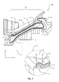
- Fig. 3 schematically shows a simplified sectional view of a section of a further turbine housing 100 according to the invention with a first reinforcing element 1c and a second reinforcing element 1c 'on an NDT housing section 5c, and a further first reinforcing element 1d on another NDT housing section 5d.
- the reinforcing elements 1 c, 1 c 'and the reinforcing element 1 d are arranged within the containment sections 16.
- the further NDT housing section 5d has only a first reinforcing element 1d.
- the further NDT housing section 5d has two shells or shell-shaped elements, the first shell being that part of the NDT housing section 5d which is connected in a planar manner to the reinforcing element 1d, and wherein the second shell is the reinforcing element 1d.
- the reinforcing elements 1c, 1c 'and 1d differ in the shape of, with respect to the view in FIG Fig. 3 , right end areas.
- the two reinforcing elements 1c, 1c ' are made in two layers or two layers, with surface contact with each other.
- the upper of the two reinforcing elements 1c is secured against the front side against a fixing element 15c against axial displacement in the axial direction (x-direction), the lower adjoins the radius of curvature of the fixing element 15d.
- the reinforcing element 1d is designed as a single-layer or single-layer.
- the reinforcing element 1d is curved or bent on the right in the axial direction (x-direction), and secured by means of the fixing element 15d against axial displacement in the axial direction (x-direction).
- Fig. 4 schematically shows a simplified sectional view of a section of a further turbine housing 100 according to the invention with at least one wound strip as the first reinforcing element 1e and second reinforcing element 1e '.
- the first reinforcing member 1e is disposed directly on the outer side 19 of the NDT housing portion 5e.
- the reinforcing members 1e, 1e ' include, for example, a wound wire or a wound composite material wound in the circumferential direction of the NDT housing portion 5e.
- the axial fixation of the reinforcing elements 1e, 1e ' is in an analogous manner to the axial fixation in Fig. 2 realized (see detail enlargement C).
- the geometric shapes, in particular the surface geometry 19 of the NDT housing section 5e are in comparison to the surface geometry 19 of the NDT housing section 5b Fig. 2 differently designed.
- the free ends of the wrapping material (wire, composite material, etc.) of the reinforcing elements 1e, 1e ' may also be used for a suitable fixation.
- the reinforcing elements 1e, 1e ' can be applied by a single winding.
- ⁇ B> LIST OF REFERENCES ⁇ / b> reference numeral description 100 turbine housing x Axial direction, main flow direction y radial direction 1a, 1b, 1c, 1d, 1e first reinforcing element 1a ', 1b' 1c ', 1e' second reinforcing element 1b " third reinforcement element 3 Inside of an NDT housing section 4 Flow direction 5a, 5b, 5c, 5d, 5e NDT housing section 6 drilling 7 end; curved ends of the reinforcing elements 1a and 1a ' 8th Bore diameter 9 Inlet pad assembly 11 housing part 13.13 ' further housing part 15 fixing element 16 Containment section 17 screw 19 Outside of an NDT housing section 21 Paragraph of the surface geometry of the NDT housing section
Landscapes
- Engineering & Computer Science (AREA)
- Mechanical Engineering (AREA)
- General Engineering & Computer Science (AREA)
- Turbine Rotor Nozzle Sealing (AREA)
- Supercharger (AREA)
Applications Claiming Priority (1)
| Application Number | Priority Date | Filing Date | Title |
|---|---|---|---|
| DE102013210602.5A DE102013210602A1 (de) | 2013-06-07 | 2013-06-07 | Turbinengehäuse mit Verstärkungselementen im Containmentbereich |
Publications (2)
| Publication Number | Publication Date |
|---|---|
| EP2811122A1 true EP2811122A1 (fr) | 2014-12-10 |
| EP2811122B1 EP2811122B1 (fr) | 2017-08-30 |
Family
ID=50721628
Family Applications (1)
| Application Number | Title | Priority Date | Filing Date |
|---|---|---|---|
| EP14168381.3A Active EP2811122B1 (fr) | 2013-06-07 | 2014-05-15 | Boîtier de turbine doté d'éléments de renforcement dans une zone de confinement |
Country Status (4)
| Country | Link |
|---|---|
| US (1) | US20140363270A1 (fr) |
| EP (1) | EP2811122B1 (fr) |
| DE (1) | DE102013210602A1 (fr) |
| ES (1) | ES2640101T3 (fr) |
Families Citing this family (7)
| Publication number | Priority date | Publication date | Assignee | Title |
|---|---|---|---|---|
| US11421627B2 (en) * | 2017-02-22 | 2022-08-23 | General Electric Company | Aircraft and direct drive engine under wing installation |
| US10550718B2 (en) | 2017-03-31 | 2020-02-04 | The Boeing Company | Gas turbine engine fan blade containment systems |
| US10487684B2 (en) | 2017-03-31 | 2019-11-26 | The Boeing Company | Gas turbine engine fan blade containment systems |
| US11428160B2 (en) | 2020-12-31 | 2022-08-30 | General Electric Company | Gas turbine engine with interdigitated turbine and gear assembly |
| US20230340890A1 (en) * | 2022-04-21 | 2023-10-26 | Pratt & Whitney Canada Corp. | Multi-layered containment structure for a bladed rotor of a gas turbine engine |
| US12297744B2 (en) | 2023-09-06 | 2025-05-13 | Pratt & Whitney Canada Corp. | Containment engine case with local features and outer surface reinforcement section |
| US12320266B2 (en) | 2023-09-06 | 2025-06-03 | Pratt & Whitney Canada Corp. | Containment engine case with local features and inner surface reinforcement section |
Citations (5)
| Publication number | Priority date | Publication date | Assignee | Title |
|---|---|---|---|---|
| US6059523A (en) * | 1998-04-20 | 2000-05-09 | Pratt & Whitney Canada Inc. | Containment system for containing blade burst |
| EP1001140A2 (fr) * | 1998-11-13 | 2000-05-17 | General Electric Company | Anneau de rétention pour carter de turbomachine |
| EP1503043A2 (fr) * | 2003-07-30 | 2005-02-02 | The Boeing Company | Dispositif de confinement plastiquement déformable et turbine avec un tel dispositif |
| US7334984B1 (en) * | 2003-12-24 | 2008-02-26 | Heico Corporation | Turbine shroud assembly with enhanced blade containment capabilities |
| WO2013095210A1 (fr) * | 2011-12-22 | 2013-06-27 | Volvo Aero Corporation | Ensemble de confinement pour turbine à gaz |
Family Cites Families (11)
| Publication number | Priority date | Publication date | Assignee | Title |
|---|---|---|---|---|
| GB2159886B (en) * | 1984-06-07 | 1988-01-27 | Rolls Royce | Fan duct casing |
| US5163809A (en) * | 1991-04-29 | 1992-11-17 | Pratt & Whitney Canada, Inc. | Spiral wound containment ring |
| GB2262313B (en) * | 1991-12-14 | 1994-09-21 | Rolls Royce Plc | Aerofoil blade containment |
| US6637186B1 (en) * | 1997-11-11 | 2003-10-28 | United Technologies Corporation | Fan case liner |
| GB0116988D0 (en) * | 2000-08-11 | 2001-09-05 | Rolls Royce Plc | A gas turbine engine blade containment assembly |
| DE10122464C1 (de) * | 2001-05-09 | 2002-03-07 | Mtu Aero Engines Gmbh | Mantelring |
| US8016543B2 (en) * | 2007-04-02 | 2011-09-13 | Michael Scott Braley | Composite case armor for jet engine fan case containment |
| US20090110538A1 (en) * | 2007-10-26 | 2009-04-30 | Pratt & Whitney Canada Corp. | Gas turbine engine blade containment using wire wrapping |
| DE102008061398A1 (de) * | 2008-12-10 | 2010-06-17 | Man Diesel Se | Berstschutz für eine Strömungsmaschine |
| US8545167B2 (en) * | 2009-08-26 | 2013-10-01 | Pratt & Whitney Canada Corp. | Composite casing for rotating blades |
| GB201020143D0 (en) * | 2010-11-29 | 2011-01-12 | Rolls Royce Plc | A gas turbine engine blade containment arrangement |
-
2013
- 2013-06-07 DE DE102013210602.5A patent/DE102013210602A1/de not_active Ceased
-
2014
- 2014-05-15 EP EP14168381.3A patent/EP2811122B1/fr active Active
- 2014-05-15 ES ES14168381.3T patent/ES2640101T3/es active Active
- 2014-06-04 US US14/295,959 patent/US20140363270A1/en not_active Abandoned
Patent Citations (5)
| Publication number | Priority date | Publication date | Assignee | Title |
|---|---|---|---|---|
| US6059523A (en) * | 1998-04-20 | 2000-05-09 | Pratt & Whitney Canada Inc. | Containment system for containing blade burst |
| EP1001140A2 (fr) * | 1998-11-13 | 2000-05-17 | General Electric Company | Anneau de rétention pour carter de turbomachine |
| EP1503043A2 (fr) * | 2003-07-30 | 2005-02-02 | The Boeing Company | Dispositif de confinement plastiquement déformable et turbine avec un tel dispositif |
| US7334984B1 (en) * | 2003-12-24 | 2008-02-26 | Heico Corporation | Turbine shroud assembly with enhanced blade containment capabilities |
| WO2013095210A1 (fr) * | 2011-12-22 | 2013-06-27 | Volvo Aero Corporation | Ensemble de confinement pour turbine à gaz |
Also Published As
| Publication number | Publication date |
|---|---|
| EP2811122B1 (fr) | 2017-08-30 |
| ES2640101T3 (es) | 2017-10-31 |
| US20140363270A1 (en) | 2014-12-11 |
| DE102013210602A1 (de) | 2014-12-11 |
Similar Documents
| Publication | Publication Date | Title |
|---|---|---|
| EP2811122B1 (fr) | Boîtier de turbine doté d'éléments de renforcement dans une zone de confinement | |
| EP1357295B1 (fr) | Compresseur axial multi-étages | |
| EP3199758B1 (fr) | Rotor dans une turbine à gaz de type blisk (disque à aubes) ou bling (bague à aubes) | |
| DE102007042767A1 (de) | Mehrschichtiger Abschirmungsring für einen Flugantrieb | |
| DE102010017062B4 (de) | Rotorblatt einer Windkraftanlage | |
| EP2884054A1 (fr) | Aube de guidage variable avec cône tronqué dans un ensemble palier | |
| CH714160B1 (de) | Verschalung für einen Turbolader und Turbolader. | |
| EP2824281B1 (fr) | Turbomachine | |
| EP3043085A1 (fr) | Agencement d'aubes pour une turbo-machine thermique à flux axial et procédé de montage d'un élément amortisseur entre deux aubes d'une couronne d'aube d'une turbo-machine thermique | |
| EP2394028B1 (fr) | Dispositif d'étanchéité sur l'arbre à aubes d'un étage de rotor d'une turbomachine axiale et son utilisation | |
| CH714847B1 (de) | Verschalung für einen Turbolader und Turbolader. | |
| EP3390784B1 (fr) | Turbomachine à plusieurs étages d'aubes directrices et procédé pour démonter en partie une telle turbomachine | |
| DE102017122230A1 (de) | Turbolader | |
| DE60002781T2 (de) | Nabe-Achse Verbindung | |
| CH714607A2 (de) | Verschalung eines Turboladers und Turbolader. | |
| EP0602631B1 (fr) | Procédé pour la construction d'une rangée d'aubes statoriques, en particulier pour un compresseur axial | |
| DE60318852T2 (de) | Apparat und Methode zur Dämpfung von Vibrationen zwischen Kompressorleitschaufeln und dem Gehäuse einer Gasturbine | |
| WO2010081466A1 (fr) | Aube directrice pour un stator d'un turbocompresseur et module correspondant | |
| EP2436878B1 (fr) | Boulons de couplage pour aubes de turbines | |
| EP3312388A1 (fr) | Pultdach dichtfin | |
| EP3392474B1 (fr) | Système de composant pour turbomachines et procédé correspondant | |
| EP3153671A1 (fr) | Dispositif de protection pour turbomachine | |
| EP2455588B1 (fr) | Moyen de fixation pour la fixation axiale d'un pied d'aube de turbomachine | |
| DE102008061398A1 (de) | Berstschutz für eine Strömungsmaschine | |
| CH716177A2 (de) | Verschalung eines Turboladers und Turbolader. |
Legal Events
| Date | Code | Title | Description |
|---|---|---|---|
| PUAI | Public reference made under article 153(3) epc to a published international application that has entered the european phase |
Free format text: ORIGINAL CODE: 0009012 |
|
| 17P | Request for examination filed |
Effective date: 20140515 |
|
| AK | Designated contracting states |
Kind code of ref document: A1 Designated state(s): AL AT BE BG CH CY CZ DE DK EE ES FI FR GB GR HR HU IE IS IT LI LT LU LV MC MK MT NL NO PL PT RO RS SE SI SK SM TR |
|
| AX | Request for extension of the european patent |
Extension state: BA ME |
|
| R17P | Request for examination filed (corrected) |
Effective date: 20150526 |
|
| RBV | Designated contracting states (corrected) |
Designated state(s): AL AT BE BG CH CY CZ DE DK EE ES FI FR GB GR HR HU IE IS IT LI LT LU LV MC MK MT NL NO PL PT RO RS SE SI SK SM TR |
|
| 17Q | First examination report despatched |
Effective date: 20160930 |
|
| GRAP | Despatch of communication of intention to grant a patent |
Free format text: ORIGINAL CODE: EPIDOSNIGR1 |
|
| INTG | Intention to grant announced |
Effective date: 20170531 |
|
| GRAS | Grant fee paid |
Free format text: ORIGINAL CODE: EPIDOSNIGR3 |
|
| GRAA | (expected) grant |
Free format text: ORIGINAL CODE: 0009210 |
|
| AK | Designated contracting states |
Kind code of ref document: B1 Designated state(s): AL AT BE BG CH CY CZ DE DK EE ES FI FR GB GR HR HU IE IS IT LI LT LU LV MC MK MT NL NO PL PT RO RS SE SI SK SM TR |
|
| REG | Reference to a national code |
Ref country code: GB Ref legal event code: FG4D Free format text: NOT ENGLISH |
|
| REG | Reference to a national code |
Ref country code: CH Ref legal event code: EP |
|
| REG | Reference to a national code |
Ref country code: AT Ref legal event code: REF Ref document number: 923775 Country of ref document: AT Kind code of ref document: T Effective date: 20170915 |
|
| REG | Reference to a national code |
Ref country code: IE Ref legal event code: FG4D Free format text: LANGUAGE OF EP DOCUMENT: GERMAN |
|
| REG | Reference to a national code |
Ref country code: DE Ref legal event code: R096 Ref document number: 502014005212 Country of ref document: DE |
|
| REG | Reference to a national code |
Ref country code: ES Ref legal event code: FG2A Ref document number: 2640101 Country of ref document: ES Kind code of ref document: T3 Effective date: 20171031 |
|
| REG | Reference to a national code |
Ref country code: NL Ref legal event code: MP Effective date: 20170830 |
|
| REG | Reference to a national code |
Ref country code: LT Ref legal event code: MG4D |
|
| PG25 | Lapsed in a contracting state [announced via postgrant information from national office to epo] |
Ref country code: HR Free format text: LAPSE BECAUSE OF FAILURE TO SUBMIT A TRANSLATION OF THE DESCRIPTION OR TO PAY THE FEE WITHIN THE PRESCRIBED TIME-LIMIT Effective date: 20170830 Ref country code: FI Free format text: LAPSE BECAUSE OF FAILURE TO SUBMIT A TRANSLATION OF THE DESCRIPTION OR TO PAY THE FEE WITHIN THE PRESCRIBED TIME-LIMIT Effective date: 20170830 Ref country code: NO Free format text: LAPSE BECAUSE OF FAILURE TO SUBMIT A TRANSLATION OF THE DESCRIPTION OR TO PAY THE FEE WITHIN THE PRESCRIBED TIME-LIMIT Effective date: 20171130 Ref country code: LT Free format text: LAPSE BECAUSE OF FAILURE TO SUBMIT A TRANSLATION OF THE DESCRIPTION OR TO PAY THE FEE WITHIN THE PRESCRIBED TIME-LIMIT Effective date: 20170830 Ref country code: SE Free format text: LAPSE BECAUSE OF FAILURE TO SUBMIT A TRANSLATION OF THE DESCRIPTION OR TO PAY THE FEE WITHIN THE PRESCRIBED TIME-LIMIT Effective date: 20170830 |
|
| PG25 | Lapsed in a contracting state [announced via postgrant information from national office to epo] |
Ref country code: LV Free format text: LAPSE BECAUSE OF FAILURE TO SUBMIT A TRANSLATION OF THE DESCRIPTION OR TO PAY THE FEE WITHIN THE PRESCRIBED TIME-LIMIT Effective date: 20170830 Ref country code: RS Free format text: LAPSE BECAUSE OF FAILURE TO SUBMIT A TRANSLATION OF THE DESCRIPTION OR TO PAY THE FEE WITHIN THE PRESCRIBED TIME-LIMIT Effective date: 20170830 Ref country code: IS Free format text: LAPSE BECAUSE OF FAILURE TO SUBMIT A TRANSLATION OF THE DESCRIPTION OR TO PAY THE FEE WITHIN THE PRESCRIBED TIME-LIMIT Effective date: 20171230 Ref country code: GR Free format text: LAPSE BECAUSE OF FAILURE TO SUBMIT A TRANSLATION OF THE DESCRIPTION OR TO PAY THE FEE WITHIN THE PRESCRIBED TIME-LIMIT Effective date: 20171201 Ref country code: BG Free format text: LAPSE BECAUSE OF FAILURE TO SUBMIT A TRANSLATION OF THE DESCRIPTION OR TO PAY THE FEE WITHIN THE PRESCRIBED TIME-LIMIT Effective date: 20171130 |
|
| PG25 | Lapsed in a contracting state [announced via postgrant information from national office to epo] |
Ref country code: NL Free format text: LAPSE BECAUSE OF FAILURE TO SUBMIT A TRANSLATION OF THE DESCRIPTION OR TO PAY THE FEE WITHIN THE PRESCRIBED TIME-LIMIT Effective date: 20170830 |
|
| PG25 | Lapsed in a contracting state [announced via postgrant information from national office to epo] |
Ref country code: RO Free format text: LAPSE BECAUSE OF FAILURE TO SUBMIT A TRANSLATION OF THE DESCRIPTION OR TO PAY THE FEE WITHIN THE PRESCRIBED TIME-LIMIT Effective date: 20170830 Ref country code: PL Free format text: LAPSE BECAUSE OF FAILURE TO SUBMIT A TRANSLATION OF THE DESCRIPTION OR TO PAY THE FEE WITHIN THE PRESCRIBED TIME-LIMIT Effective date: 20170830 Ref country code: CZ Free format text: LAPSE BECAUSE OF FAILURE TO SUBMIT A TRANSLATION OF THE DESCRIPTION OR TO PAY THE FEE WITHIN THE PRESCRIBED TIME-LIMIT Effective date: 20170830 Ref country code: DK Free format text: LAPSE BECAUSE OF FAILURE TO SUBMIT A TRANSLATION OF THE DESCRIPTION OR TO PAY THE FEE WITHIN THE PRESCRIBED TIME-LIMIT Effective date: 20170830 |
|
| REG | Reference to a national code |
Ref country code: FR Ref legal event code: PLFP Year of fee payment: 5 |
|
| PG25 | Lapsed in a contracting state [announced via postgrant information from national office to epo] |
Ref country code: IT Free format text: LAPSE BECAUSE OF FAILURE TO SUBMIT A TRANSLATION OF THE DESCRIPTION OR TO PAY THE FEE WITHIN THE PRESCRIBED TIME-LIMIT Effective date: 20170830 Ref country code: SM Free format text: LAPSE BECAUSE OF FAILURE TO SUBMIT A TRANSLATION OF THE DESCRIPTION OR TO PAY THE FEE WITHIN THE PRESCRIBED TIME-LIMIT Effective date: 20170830 Ref country code: SK Free format text: LAPSE BECAUSE OF FAILURE TO SUBMIT A TRANSLATION OF THE DESCRIPTION OR TO PAY THE FEE WITHIN THE PRESCRIBED TIME-LIMIT Effective date: 20170830 Ref country code: EE Free format text: LAPSE BECAUSE OF FAILURE TO SUBMIT A TRANSLATION OF THE DESCRIPTION OR TO PAY THE FEE WITHIN THE PRESCRIBED TIME-LIMIT Effective date: 20170830 |
|
| REG | Reference to a national code |
Ref country code: DE Ref legal event code: R097 Ref document number: 502014005212 Country of ref document: DE |
|
| PLBE | No opposition filed within time limit |
Free format text: ORIGINAL CODE: 0009261 |
|
| STAA | Information on the status of an ep patent application or granted ep patent |
Free format text: STATUS: NO OPPOSITION FILED WITHIN TIME LIMIT |
|
| 26N | No opposition filed |
Effective date: 20180531 |
|
| PG25 | Lapsed in a contracting state [announced via postgrant information from national office to epo] |
Ref country code: SI Free format text: LAPSE BECAUSE OF FAILURE TO SUBMIT A TRANSLATION OF THE DESCRIPTION OR TO PAY THE FEE WITHIN THE PRESCRIBED TIME-LIMIT Effective date: 20170830 |
|
| PG25 | Lapsed in a contracting state [announced via postgrant information from national office to epo] |
Ref country code: MT Free format text: LAPSE BECAUSE OF FAILURE TO SUBMIT A TRANSLATION OF THE DESCRIPTION OR TO PAY THE FEE WITHIN THE PRESCRIBED TIME-LIMIT Effective date: 20170830 |
|
| REG | Reference to a national code |
Ref country code: CH Ref legal event code: PL |
|
| REG | Reference to a national code |
Ref country code: BE Ref legal event code: MM Effective date: 20180531 |
|
| PG25 | Lapsed in a contracting state [announced via postgrant information from national office to epo] |
Ref country code: MC Free format text: LAPSE BECAUSE OF FAILURE TO SUBMIT A TRANSLATION OF THE DESCRIPTION OR TO PAY THE FEE WITHIN THE PRESCRIBED TIME-LIMIT Effective date: 20170830 |
|
| REG | Reference to a national code |
Ref country code: IE Ref legal event code: MM4A |
|
| PG25 | Lapsed in a contracting state [announced via postgrant information from national office to epo] |
Ref country code: LI Free format text: LAPSE BECAUSE OF NON-PAYMENT OF DUE FEES Effective date: 20180531 Ref country code: CH Free format text: LAPSE BECAUSE OF NON-PAYMENT OF DUE FEES Effective date: 20180531 |
|
| PG25 | Lapsed in a contracting state [announced via postgrant information from national office to epo] |
Ref country code: LU Free format text: LAPSE BECAUSE OF NON-PAYMENT OF DUE FEES Effective date: 20180515 |
|
| PG25 | Lapsed in a contracting state [announced via postgrant information from national office to epo] |
Ref country code: IE Free format text: LAPSE BECAUSE OF NON-PAYMENT OF DUE FEES Effective date: 20180515 |
|
| PG25 | Lapsed in a contracting state [announced via postgrant information from national office to epo] |
Ref country code: BE Free format text: LAPSE BECAUSE OF NON-PAYMENT OF DUE FEES Effective date: 20180531 |
|
| PG25 | Lapsed in a contracting state [announced via postgrant information from national office to epo] |
Ref country code: TR Free format text: LAPSE BECAUSE OF FAILURE TO SUBMIT A TRANSLATION OF THE DESCRIPTION OR TO PAY THE FEE WITHIN THE PRESCRIBED TIME-LIMIT Effective date: 20170830 |
|
| PG25 | Lapsed in a contracting state [announced via postgrant information from national office to epo] |
Ref country code: PT Free format text: LAPSE BECAUSE OF FAILURE TO SUBMIT A TRANSLATION OF THE DESCRIPTION OR TO PAY THE FEE WITHIN THE PRESCRIBED TIME-LIMIT Effective date: 20170830 Ref country code: HU Free format text: LAPSE BECAUSE OF FAILURE TO SUBMIT A TRANSLATION OF THE DESCRIPTION OR TO PAY THE FEE WITHIN THE PRESCRIBED TIME-LIMIT; INVALID AB INITIO Effective date: 20140515 |
|
| PG25 | Lapsed in a contracting state [announced via postgrant information from national office to epo] |
Ref country code: MK Free format text: LAPSE BECAUSE OF NON-PAYMENT OF DUE FEES Effective date: 20170830 Ref country code: CY Free format text: LAPSE BECAUSE OF FAILURE TO SUBMIT A TRANSLATION OF THE DESCRIPTION OR TO PAY THE FEE WITHIN THE PRESCRIBED TIME-LIMIT Effective date: 20170830 |
|
| PG25 | Lapsed in a contracting state [announced via postgrant information from national office to epo] |
Ref country code: AL Free format text: LAPSE BECAUSE OF FAILURE TO SUBMIT A TRANSLATION OF THE DESCRIPTION OR TO PAY THE FEE WITHIN THE PRESCRIBED TIME-LIMIT Effective date: 20170830 |
|
| REG | Reference to a national code |
Ref country code: AT Ref legal event code: MM01 Ref document number: 923775 Country of ref document: AT Kind code of ref document: T Effective date: 20190515 |
|
| PG25 | Lapsed in a contracting state [announced via postgrant information from national office to epo] |
Ref country code: AT Free format text: LAPSE BECAUSE OF NON-PAYMENT OF DUE FEES Effective date: 20190515 |
|
| PGFP | Annual fee paid to national office [announced via postgrant information from national office to epo] |
Ref country code: DE Payment date: 20250519 Year of fee payment: 12 |
|
| PGFP | Annual fee paid to national office [announced via postgrant information from national office to epo] |
Ref country code: GB Payment date: 20250522 Year of fee payment: 12 Ref country code: ES Payment date: 20250616 Year of fee payment: 12 |
|
| PGFP | Annual fee paid to national office [announced via postgrant information from national office to epo] |
Ref country code: FR Payment date: 20250523 Year of fee payment: 12 |