EP2811153A1 - Anlasser - Google Patents
Anlasser Download PDFInfo
- Publication number
- EP2811153A1 EP2811153A1 EP14170553.3A EP14170553A EP2811153A1 EP 2811153 A1 EP2811153 A1 EP 2811153A1 EP 14170553 A EP14170553 A EP 14170553A EP 2811153 A1 EP2811153 A1 EP 2811153A1
- Authority
- EP
- European Patent Office
- Prior art keywords
- output shaft
- housing
- pinion gear
- flat washer
- clutch
- Prior art date
- Legal status (The legal status is an assumption and is not a legal conclusion. Google has not performed a legal analysis and makes no representation as to the accuracy of the status listed.)
- Withdrawn
Links
Images



Classifications
-
- F—MECHANICAL ENGINEERING; LIGHTING; HEATING; WEAPONS; BLASTING
- F02—COMBUSTION ENGINES; HOT-GAS OR COMBUSTION-PRODUCT ENGINE PLANTS
- F02N—STARTING OF COMBUSTION ENGINES; STARTING AIDS FOR SUCH ENGINES, NOT OTHERWISE PROVIDED FOR
- F02N15/00—Other power-operated starting apparatus; Component parts, details, or accessories, not provided for in, or of interest apart from groups F02N5/00 - F02N13/00
- F02N15/02—Gearing between starting-engines and started engines; Engagement or disengagement thereof
- F02N15/04—Gearing between starting-engines and started engines; Engagement or disengagement thereof the gearing including disengaging toothed gears
- F02N15/06—Gearing between starting-engines and started engines; Engagement or disengagement thereof the gearing including disengaging toothed gears the toothed gears being moved by axial displacement
- F02N15/066—Gearing between starting-engines and started engines; Engagement or disengagement thereof the gearing including disengaging toothed gears the toothed gears being moved by axial displacement the starter being of the coaxial type
-
- F—MECHANICAL ENGINEERING; LIGHTING; HEATING; WEAPONS; BLASTING
- F02—COMBUSTION ENGINES; HOT-GAS OR COMBUSTION-PRODUCT ENGINE PLANTS
- F02N—STARTING OF COMBUSTION ENGINES; STARTING AIDS FOR SUCH ENGINES, NOT OTHERWISE PROVIDED FOR
- F02N15/00—Other power-operated starting apparatus; Component parts, details, or accessories, not provided for in, or of interest apart from groups F02N5/00 - F02N13/00
- F02N15/02—Gearing between starting-engines and started engines; Engagement or disengagement thereof
- F02N15/04—Gearing between starting-engines and started engines; Engagement or disengagement thereof the gearing including disengaging toothed gears
- F02N15/06—Gearing between starting-engines and started engines; Engagement or disengagement thereof the gearing including disengaging toothed gears the toothed gears being moved by axial displacement
- F02N15/062—Starter drives
- F02N15/063—Starter drives with resilient shock absorbers
-
- F—MECHANICAL ENGINEERING; LIGHTING; HEATING; WEAPONS; BLASTING
- F02—COMBUSTION ENGINES; HOT-GAS OR COMBUSTION-PRODUCT ENGINE PLANTS
- F02N—STARTING OF COMBUSTION ENGINES; STARTING AIDS FOR SUCH ENGINES, NOT OTHERWISE PROVIDED FOR
- F02N11/00—Starting of engines by means of electric motors
-
- F—MECHANICAL ENGINEERING; LIGHTING; HEATING; WEAPONS; BLASTING
- F02—COMBUSTION ENGINES; HOT-GAS OR COMBUSTION-PRODUCT ENGINE PLANTS
- F02N—STARTING OF COMBUSTION ENGINES; STARTING AIDS FOR SUCH ENGINES, NOT OTHERWISE PROVIDED FOR
- F02N15/00—Other power-operated starting apparatus; Component parts, details, or accessories, not provided for in, or of interest apart from groups F02N5/00 - F02N13/00
- F02N15/02—Gearing between starting-engines and started engines; Engagement or disengagement thereof
- F02N15/022—Gearing between starting-engines and started engines; Engagement or disengagement thereof the starter comprising an intermediate clutch
- F02N15/023—Gearing between starting-engines and started engines; Engagement or disengagement thereof the starter comprising an intermediate clutch of the overrunning type
-
- F—MECHANICAL ENGINEERING; LIGHTING; HEATING; WEAPONS; BLASTING
- F02—COMBUSTION ENGINES; HOT-GAS OR COMBUSTION-PRODUCT ENGINE PLANTS
- F02N—STARTING OF COMBUSTION ENGINES; STARTING AIDS FOR SUCH ENGINES, NOT OTHERWISE PROVIDED FOR
- F02N15/00—Other power-operated starting apparatus; Component parts, details, or accessories, not provided for in, or of interest apart from groups F02N5/00 - F02N13/00
- F02N15/02—Gearing between starting-engines and started engines; Engagement or disengagement thereof
- F02N15/022—Gearing between starting-engines and started engines; Engagement or disengagement thereof the starter comprising an intermediate clutch
- F02N15/026—Gearing between starting-engines and started engines; Engagement or disengagement thereof the starter comprising an intermediate clutch of the centrifugal type
-
- F—MECHANICAL ENGINEERING; LIGHTING; HEATING; WEAPONS; BLASTING
- F02—COMBUSTION ENGINES; HOT-GAS OR COMBUSTION-PRODUCT ENGINE PLANTS
- F02N—STARTING OF COMBUSTION ENGINES; STARTING AIDS FOR SUCH ENGINES, NOT OTHERWISE PROVIDED FOR
- F02N15/00—Other power-operated starting apparatus; Component parts, details, or accessories, not provided for in, or of interest apart from groups F02N5/00 - F02N13/00
- F02N15/02—Gearing between starting-engines and started engines; Engagement or disengagement thereof
- F02N15/04—Gearing between starting-engines and started engines; Engagement or disengagement thereof the gearing including disengaging toothed gears
- F02N15/043—Gearing between starting-engines and started engines; Engagement or disengagement thereof the gearing including disengaging toothed gears the gearing including a speed reducer
- F02N15/046—Gearing between starting-engines and started engines; Engagement or disengagement thereof the gearing including disengaging toothed gears the gearing including a speed reducer of the planetary type
-
- F—MECHANICAL ENGINEERING; LIGHTING; HEATING; WEAPONS; BLASTING
- F02—COMBUSTION ENGINES; HOT-GAS OR COMBUSTION-PRODUCT ENGINE PLANTS
- F02N—STARTING OF COMBUSTION ENGINES; STARTING AIDS FOR SUCH ENGINES, NOT OTHERWISE PROVIDED FOR
- F02N15/00—Other power-operated starting apparatus; Component parts, details, or accessories, not provided for in, or of interest apart from groups F02N5/00 - F02N13/00
- F02N15/02—Gearing between starting-engines and started engines; Engagement or disengagement thereof
- F02N15/04—Gearing between starting-engines and started engines; Engagement or disengagement thereof the gearing including disengaging toothed gears
- F02N15/06—Gearing between starting-engines and started engines; Engagement or disengagement thereof the gearing including disengaging toothed gears the toothed gears being moved by axial displacement
- F02N15/067—Gearing between starting-engines and started engines; Engagement or disengagement thereof the gearing including disengaging toothed gears the toothed gears being moved by axial displacement the starter comprising an electro-magnetically actuated lever
Definitions
- the present invention relates to, for example, a starter mounted on a car.
- a plunging-type starter in which startup of an engine is performed in such a manner that a pinion gear plunges into a ring gear at the time of startup of the engine and engages with the ring gear to drive the ring gear through the pinion gear and rotate a crankshaft is conventionally known as a starter used to startup of a car (e.g., see Japanese Unexamined Patent Application, First Publication No. 2002-130097 ).
- a driving shaft (output shaft) is connected to a rotor shaft of a startup motor through a planetary-gear-style speed reducer. Both end sides in an axial direction of the driving shaft are rotatably supported by a housing of the starter.
- a mover that moves forward and backward in an axial direction by means of a magnet switch (electromagnetic device) through a lever spline-engages with the driving shaft.
- the pinion gear is provided in the driving shaft to be movable forward and backward in the axial direction toward the ring gear.
- the ring gear and the pinion gear include a helical gear, and a torsional direction of the teeth of the ring gear and the pinion gear is set so that a thrust load in a plunging direction is applied to the pinion gear in a state in which the pinion gear drives the ring gear.
- the pinion gear receives the thrust load generated by a torsional angle of the teeth of both of the gears and proceeds by itself in a plunging direction, and engagement of the pinion gear with the ring gear can be improved. Further, an engagement area of the ring gear and the pinion gear increases, and operating noise generated by the engagement can be reduced.
- the thrust load is also applied to the output shaft connected to the mover. Accordingly, since the output shaft slides to the ring gear, an end surface on one side of the output shaft may come in sliding contact with the housing.
- a speed difference between the rotational speed of the ring gear and the rotational speed of the pinion gear is repeatedly reversed when a crankshaft passes through a top dead center and a bottom dead center while the ring gear and the pinion gear engage to start up the engine.
- a direction of the thrust load applied to the output shaft is also repeatedly reversed.
- the present invention provides a starter capable of improving durability of a housing and reducing noise at the time of driving without causing an increase in cost or size.
- a starter includes a motor portion that generates rotational force through application of an electric current; an output shaft that receives the rotational force of the motor portion and rotates; a housing that rotatably supports an end portion on at least one side of the output shaft; a pinion gear that is provided to be slidable on the output shaft, and is capable of helically engaging with a ring gear of the engine; a clutch mechanism that is provided between the output shaft and the pinion gear and transmits the rotational force of the output shaft to the pinion gear; a movement regulation portion that is provided in the output shaft, and regulates sliding of the pinion gear and the clutch mechanism by a predetermined value or more toward the one side; an electromagnetic device that applies and blocks an electric current to the motor portion and biases pressing force directed to the ring gear to the pinion gear through the clutch mechanism.
- a damper means that mitigates shock in an axial direction from the output shaft to the housing is provided between the housing and the end portion on the one side of the output shaft
- the damper means of the starter according to the first aspect includes a load receiving member that abuts the end portion on the one side of the output shaft; and an elastic member provided between the load receiving member and the housing.
- the load receiving member of the starter according to the second aspect is a flat washer, and the elastic member includes an annular rubber material.
- the load receiving member of the starter according to the second aspect is a flat washer, and the elastic member includes a cylindrical rubber material.
- the end portion of at least the one side of the output shaft in the starter according to any one of the second to fourth aspect is rotatably supported on the housing through a radial bearing, movement in a falling-out direction of the load receiving member is regulated by the radial bearing, and the elastic member is arranged between the load receiving member and the housing.
- the load receiving member and the elastic member are attached to the housing easily and reliably, and it is possible to prevent the load receiving member and the elastic member from unexpectedly falling off.
- the flat washer of the starter according to any one of the third to fifth aspect is formed by performing press working on a metal plate
- the housing includes a bottom portion arranged in a state in which one surface of the flat washer is capable of abutting the one side of the output shaft, and an escape portion is formed to be recessed toward the one side in a position corresponding to a peripheral edge portion of the flat washer of the bottom portion.
- the flat washer of the starter according to any one of the third to fifth aspect is formed by performing press working on a metal plate
- the housing includes a step portion arranged in a state in which one surface of the flat washer is capable of abutting the one side of the output shaft, and a recessed portion is formed to be recessed toward the one side in a position corresponding to a peripheral edge portion of the flat washer of the step portion.
- the elastic member is arranged in the escape portion.
- the housing of the starter according to the seventh aspect includes a bottom portion on the one side of the output shaft, and the elastic member is arranged between the bottom portion and the step portion.
- the electromagnetic device is provided coaxially with the output shaft.
- the present invention can preferably be adopted in a so-called one-shaft-type starter in which the electromagnetic device and the output shaft are coaxially provided. Therefore, it is possible to obtain a starter having excellent durability while suppressing an increase in cost or size of the housing even in the one-shaft-type starter. Further, it is possible to reduce noise when the starter is driven.
- the starter described above even when the pinion gear helically engages with the ring gear and moves to the ring gear and the thrust load is applied to the output shaft through the movement regulation portion, it is possible to effectively mitigate shock in the axial direction from the output shaft to the housing while regulating the movement of the output shaft using the damper means. Further, since the end portion on one side of the output shaft and the damper means come in sliding contact at the time of rotation of the output shaft, the end portion on one side of the output shaft and the housing can be prevented from coming in direct sliding contact.
- FIGS. 1 to 8 Next, a first embodiment of the present invention will be described based on FIGS. 1 to 8 .
- FIG. 1 is a cross-sectional view of a starter 1. Further, in FIG. 1 , a stop state of the starter 1 is shown above a center line and an electric current applying state of the starter 1 (a state in a process when a pinion gear 74 and a ring gear 23 engage) is shown therebelow.
- the starter 1 is a device used to generate rotational force necessary for startup of an engine that is not shown, and includes a motor portion 3, an output shaft 4 connected to one side (the left side in FIG. 1 ) of the motor portion 3, a clutch mechanism 5 and a pinion mechanism 70 slidably provided on the output shaft 4, a switch unit 7 which opens or closes a power supply path for the motor portion 3, and an electromagnetic device 9 used to move a movable contact plate 8 of the switch unit 7 and the pinion mechanism 70 in an axial direction, as shown in FIG. 1 .
- the motor portion 3 includes a brush direct current motor 51, and a planetary gear mechanism 2 connected to a rotation shaft 52 of the brush direct current motor 51 used to transmit the rotational force of this rotation shaft 52 to the output shaft 4.
- the brush direct current motor 51 includes a substantially cylindrical motor yoke 53, and an armature 54 arranged on an inner side in a diameter direction of the motor yoke 53 and provided rotatably with respect to the motor yoke 53.
- a plurality (six magnets in this embodiment) of permanent magnets 57 are provided on an inner circumferential surface of the motor yoke 53 so that magnetic poles alternate in a circumferential direction.
- An end plate 55 that closes an opening 53a of the motor yoke 53 is provided in an end on the other side of the motor yoke 53 (on the right side in FIG. 1 ).
- a sliding bearing 56a and a thrust bearing 56b which rotatably supports the other end of the rotation shaft 52 are provided at a center in the diameter direction of the end plate 55.
- the armature 54 includes the rotation shaft 52, an armature core 58 externally fitted and fixed in a position corresponding to the permanent magnet 57 of the rotation shaft 52, and a commutator 61 externally fitted and fixed on the planetary gear mechanism 2 side (the left side in FIG. 1 ) in comparison with the armature core 58 of the rotation shaft 52.
- the armature core 58 includes a plurality of radially formed teeth (not shown), and a plurality of slots (none of which is shown) formed between respective circumferentially adjacent teeth.
- a coil 59 is wound between the respective slots at predetermined circumferential intervals, for example, through wave winding. A terminal portion of the coil 59 is drawn toward the commutator 61.
- a plurality (e.g., twenty six segments in this embodiment) of segments 62 are provided in a circumferential direction and at predetermined intervals to be electrically insulated from each other in the commutator 61.
- a riser 63 that is bent and formed to fold back is provided in an end on the armature core 58 side of each segment 62.
- the terminal portion of the coil 59 wound around the armature core 58 is connected to the riser 63.
- a bottomed cylindrical top plate 12 is provided on a side opposite to the end plate 55 of the motor yoke 53.
- the planetary gear mechanism 2 is provided in an inner surface on the armature core 58 side in the top plate 12.
- the planetary gear mechanism 2 includes a sun gear 13 integrally molded with the rotation shaft 52, a plurality of planetary gears 14 engaging with the sun gear 13 and revolving around the sun gear 13, and an inner tooth ring gear 15 having an annular shape provided on an outer circumferential side of the planetary gear 14.
- the plurality of planetary gears 14 are connected by a carrier plate 16.
- a plurality of support shafts 16a stand in positions corresponding to the respective planetary gears 14 in the carrier plate 16, and the planetary gears 14 are rotatably supported thereon. Further, the output shaft 4 engages through serration engagement at a center part in the diameter direction of the carrier plate 16.
- the inner tooth ring gear 15 is integrally molded in an inner circumferential surface on the armature core 58 side of the top plate 12.
- a sliding bearing 12a is provided at a center in the diameter direction in the inner circumferential surface of the top plate 12.
- the sliding bearing 12a rotatably supports an end portion 104a on the other side (an end on the right side in FIG. 1 ) of the output shaft 4 arranged coaxially with the rotation shaft 52.
- a bottomed cylindrical housing 17 is externally fitted and fixed to the top plate 12.
- the housing 17 is a member formed through aluminum die-casting, and the output shaft 4, the clutch mechanism 5, the pinion mechanism 70, the electromagnetic device 9 or the like are included in the housing 17. Further, the housing 17 has a function to fix the starter 1 to the engine that is not shown.
- a female thread portion 17b is carved in an axial direction in an outer circumferential surface on the opening 17a side of the housing 17. Further, a bolt hole 55a is formed in a position corresponding to the female thread portion 17b in the end plate 55 arranged on the other side (a right end side in FIG. 1 ) of the motor yoke 53. A bolt 95 is inserted into this bolt hole 55a and screwed in the female thread portion 17b such that the motor portion 3 and the housing 17 are integrally formed.
- a ring-shaped stopper 94 regulating displacement to the motor portion 3 of the clutch outer 18 to be described below is provided in an inner wall of the housing 17.
- This stopper 94 is formed of a resin, rubber or the like, and is configured to be able to mitigate shock when abutted by the clutch outer 18.
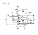
- FIG. 2 is an enlarged view of the bottom portion 17c of the housing 17, and is an illustrative view of a damper portion 50.
- a bearing recessed portion 47 having a section in a substantially circular shape is formed coaxially with the output shaft 4 in the bottom portion 17c of the housing 17.
- a sliding bearing 17d serving as a radial bearing which rotatably supports the end portion 104b on one side (the left side in FIG. 1 ) of the output shaft 4 is pressed and fixed to an inner circumferential surface 47a of the bearing recessed portion 47.
- Lubricant oil including desired base oil is impregnated in the sliding bearing 17d, and the output shaft 4 inserted into the inner circumferential surface can smoothly come in sliding contact therewith.
- a length L1 of the sliding bearing 17d is set to be smaller than a depth H1 of the bearing recessed portion 47. Therefore, a gap S1 is formed between an end portion on one side (the left side in FIG. 2 ) of the sliding bearing 17d and the bottom portion 47b of the bearing recessed portion 47.
- the damper portion 50 is arranged in this gap S1.
- the damper portion 50 is a member used to mitigate shock due to the thrust load applied from the output shaft 4 to the bottom portion 17c of the housing 17.
- the damper portion 50 includes a flat washer 50a serving as a damper means or a load receiving member and a rubber damper 50b serving as an elastic member.
- the flat washer 50a is a member formed in an annular shape by performing press working on a metal plate having excellent abrasion resistance and having a higher hardness than the output shaft 4.
- carbon tool steel such as SK85 is used as a specific material of the flat washer 50a.
- the flat washer 50a is formed with a thickness such that the flat washer 50a can be arranged between the end portion 104b on one side of the output shaft 4 and the bottom portion 47b of the bearing recessed portion 47.
- a diameter D4 of the flat washer 50a is set to be substantially equal to or slightly smaller than the diameter of the inner circumferential surface 47a of the bearing recessed portion 47. Accordingly, the flat washer 50a can be arranged in the gap S 1. Further, the diameter D4 of the flat washer 50a is set to be greater than the inner diameter D5 of the sliding bearing 17d. Accordingly, the flat washer 50a and the rubber damper 50b do not fall off the housing 17 in a state in which the sliding bearing 17d is pressed into the housing 17 (details will be described below).
- the flat washer 50a formed in this way is arranged in a state in which burrs generated when press working is performed are directed to the bottom portion 47b of the bearing recessed portion 47.
- the rubber damper 50b is arranged between the flat washer 50a and the bottom portion 47b of the bearing recessed portion 47.
- the rubber damper 50b is a member formed in a substantial ring shape, and an outer diameter thereof is set to be slightly smaller than the diameter D4 of the flat washer 50a. Accordingly, it is possible to prevent the rubber damper 50b from being damaged by the burrs of the flat washer 50a. It is preferable, for example, for acrylic rubber or nitrile rubber to be used as a material of the rubber damper 50b.
- a first escape groove 47c that is substantially annular when viewed in a plan view is formed in an axial direction on the outer circumferential side in the bottom portion 47b of the bearing recessed portion 47.
- the first escape groove 47c is formed in a position corresponding to the outer peripheral edge portion of the flat washer 50a in the bottom portion 47b of the bearing recessed portion 47.
- This first escape groove 47c functions as an accommodating portion that accommodates the rubber damper 50b. It is possible to prevent a width W1 of the gap S1 from needlessly increasing by forming the first escape groove 47c.
- a depth H2 of the first escape groove 47c is set to a depth of about half the thickness of the rubber damper 50b, and a groove width D6 is set to about 3 times the thickness of the rubber damper 50b.
- an amount of bending when the flat washer 50a receives the thrust load of the output shaft 4 can be regulated using the bottom portion 47b of the bearing recessed portion 47.
- one surface of the flat washer 50a abuts the bottom portion 47b of the bearing recessed portion 47. Accordingly, expansion to an inner side and an outer side in the diameter direction due to compression of the rubber damper 50b is allowed, and it is possible to prevent the flat washer 50a from being unnecessarily bent while regulating the compression amount in an axial direction.
- a second escape groove 47d having a substantially circular shape when viewed in a plan view is formed at substantially a center in the diameter direction in the bottom portion 47b of the bearing recessed portion 47.
- the second escape groove 47d having a substantially circular shape when viewed in a plan view is formed in a position corresponding to an inner peripheral edge portion of the flat washer 50a in the bottom portion 47b of the bearing recessed portion 47.
- a recessed portion 4a into which the end 52a on the one side of the rotation shaft 52 can be inserted is formed in the end portion 104a on the other side of the output shaft 4, as shown in FIG. 1 .
- the sliding bearing 4b is pressed into an inner circumferential surface of the recessed portion 4a, such that the output shaft 4 and the rotation shaft 52 are connected to be relatively rotatable.
- a helical spline 19 is formed at a substantial center in an axial direction of the output shaft 4.
- a clutch outer 18 of the clutch mechanism 5 to be described below helically engages with the helical spline 19.
- FIG. 3 is an exploded perspective view of the clutch mechanism 5 and the pinion mechanism 70.
- FIG. 4 is a cross-sectional view of the clutch mechanism 5 and the pinion mechanism 70.
- FIG. 5 is a plan view of the clutch mechanism 5.
- the clutch mechanism 5 includes a bottomed cylindrical clutch outer 18, a clutch inner 22 formed concentrically with the clutch outer 18, a cylindrical clutch roller 111 arranged between a circumferential wall 18a of the clutch outer 18 and an outer circumferential surface 22a of the clutch inner 22, a coil spring 112, a thrust plate 113 arranged on the opening 18b side of the clutch outer 18, and a clutch cover 114 that covers this thrust plate 113 and the clutch outer 18 from the outside, as shown in FIGS. 3 to 5 .
- the clutch mechanism 5 has a so-called known one-way clutch function used to transmit rotational force from the clutch outer 18 to the clutch inner 22, but not transmitting rotational force from the clutch inner 22 to the clutch outer 18. Accordingly, when a state enters an overrun state in which the clutch inner 22 becomes faster than the clutch outer 18 at the time of engine startup, the rotational force from the ring gear 23 of the engine that is not shown is blocked.
- the clutch mechanism 5 has a so-called torque limiter function used to transmit the rotational force to the clutch outer 18 or the clutch inner 22 when the torque difference and a rotational speed difference generated between the clutch outer 18 and the clutch inner 22 is less than a predetermined value, and to block the transmittance of the rotational force when the torque difference and the rotational speed difference exceeds the predetermined value.
- a sleeve 18d is formed to project toward the motor portion 3 at the center in the diameter direction in the bottom wall 18c of the clutch outer 18.
- the sleeve 18d is formed with a reduced diameter form in comparison with the circumferential wall 18a of the clutch outer 18, and is externally fitted to the output shaft 4.
- a helical spline 18e engaging with the helical spline 19 of the output shaft 4 is formed in an inner circumferential surface of the sleeve 18d.
- an inclination angle of the helical spline 19 of the output shaft 4 and the helical spline 18e of the clutch outer 18 is set, for example, to about 16° with respect to the axial direction.
- a step portion 18f is formed in a connection portion with the sleeve 18d on an inner surface in the bottom wall 18c of the clutch outer 18.
- a movement regulation portion 20 to be described below is configured to abut this step portion 18f.
- a plurality (5 in this embodiment) of recesses 115 are formed at uniform intervals in a circumferential direction on an inner circumferential surface side in the circumferential wall 18a of the clutch outer 18.
- the recessed portion 115 has a shape formed by communication between the roller accommodating portion 115a and the spring accommodating portion 115b.
- the roller accommodating portion 115a is a portion used to accommodate the clutch roller 111 and is formed in such a manner that the depth thereof gradually decreases in a direction opposite to the spring accommodating portion 115b, that is, a counterclockwise direction in FIG. 5 (a direction indicated by an arrow CCW in FIG. 5 ).
- the spring accommodating portion 115b is a portion used to accommodate the coil spring 112, and is formed in such a manner that the coil spring 112 can be arranged in the circumferential direction.
- the coil spring 112 always biases the clutch roller 111 in the counterclockwise direction in FIG. 5 .
- the thrust plate 113 arranged on the opening 18b side of the clutch outer 18 is a member used to receive the thrust load and preventing the clutch roller 111 or the coil spring 112 from falling out when the thrust load in the falling-out direction from the clutch outer 18 is applied to the clutch roller 111 or the coil spring 112.
- the thrust plate 113 is formed in substantially a disk shape, and an insertion hole 113a into which the clutch inner 22 can be inserted is formed at a center in the diameter direction. Further, four anti-rotation grooves 113b are formed at uniform intervals in the circumferential direction in an outer circumferential circle of the thrust plate 113. These anti-rotation grooves 113b are configured to prevent the thrust plate 113 from rotating in the circumferential direction, in cooperation with an anti-rotation projection 116 of the clutch cover 114 to be described below.
- the clutch cover 114 covering the thrust plate 113 and the clutch outer 18 formed in this way from the outside is attached from the opening 18b side of the clutch outer 18.
- the clutch cover 114 is formed in a bottomed cylindrical shape, and is externally fitted to the clutch outer 18 in a state in which the bottom wall 114a is directed to the opening 18b of the clutch outer 18.
- the clutch cover 114 is fixed to the clutch outer 18 by swaging a distal end (the right end in FIG. 4 ) of the circumferential wall 114b of the clutch cover 114.
- anti-rotation projections 114c are formed to project toward the thrust plate 113 in the bottom wall 114a of the clutch cover 114.
- the anti-rotation projections 114c are arranged at uniform intervals in the circumferential direction on the outer circumferential side of the bottom wall 114a.
- the diameter of the anti-rotation projection 114c is set to such a size that the anti-rotation projection 114c can be inserted into the anti-rotation groove 113b of the thrust plate 113. Accordingly, the anti-rotation projection 114c and the anti-rotation groove 113b cooperate to prevent rotation in the circumferential direction of the thrust plate 113.
- an insertion hole 114d into which the clutch inner 22 can be inserted is formed at a center in the diameter direction in the bottom wall 114a of the clutch cover 114.
- a substantially annular rib 114e is formed to stand facing an outer side in an axial direction in a peripheral edge of the insertion hole 114d. Accordingly, rigidity of the bottom wall 114a of the clutch cover 114 is secured.
- the clutch inner 22 is formed with a greater diameter than the sleeve 18d of the clutch outer 18 and is configured in such a manner that a gap K1 is formed between the clutch inner 22 and the output shaft 4, as shown in detail in FIG. 4 .
- a return spring 21 to be described below is inserted in a position corresponding to the gap K1 of the output shaft 4.
- a reduced diameter portion 22b in which a diameter of its outer circumferential surface is reduced due a step is integrally molded from a place corresponding to the thrust plate 113 of the clutch inner 22 to the distal end (one side; the left side in FIG. 4 ).
- the thrust plate 113 abuts a step surface 22c of this reduced diameter portion 22b.
- an end portion on a side opposite to the reduced diameter portion 22b of the clutch inner 22 abuts the bottom wall 18c of the clutch outer 18. Accordingly, the clutch inner 22 is interposed in an axial direction between the thrust plate 113 and the bottom wall 18c of the clutch outer 18. Therefore, a relative position of the clutch outer 18 and the clutch inner 22 is determined.
- substantially ring-shaped movement regulation portion 20 is externally fitted to one side (the left side in FIG. 1 ) relative to the helical spline 19 in a position corresponding to the gap K1 of the output shaft 4.
- the movement regulation portion 20 is in a state in which movement to one side in the axial direction is regulated by a circlip 20a.
- the outer diameter of the movement regulation portion 20 is set to such a size that the movement regulation portion 20 can abut the step portion 18f of the clutch outer 18. Accordingly, when the clutch mechanism 5 slides to one side, interference occurs between the sleeve 18d of the clutch outer 18 and the movement regulation portion 20. Accordingly, an amount of the sliding movement to the one side of the clutch mechanism 5 is regulated.
- the return spring 21 inserted into the output shaft 4 is compressed and deformed between the movement regulation portion 20 and the sleeve 18d of the clutch outer 18. Accordingly, the clutch outer 18 is always biased to be pushed back toward the motor portion 3.
- the pinion mechanism 70 is integrally provided in the distal end of the clutch inner 22.
- the pinion mechanism 70 includes a cylindrical pinion inner 71 which is integrally molded in the distal end of the clutch inner 22.
- Two sliding bearings 72 and 72 which slidably supports the pinion inner 71 to the output shaft 4 are provided on both sides in the axial direction in the inner circumferential surface of the pinion inner 71.
- the outer circumferential surface thereof is formed to gradually increase in diameter due to a step from the pinion inner 71 to the clutch inner 22.
- the pinion inner 71 includes a first cylindrical portion 171 arranged on one side (the left side in FIG. 4 ), and a second cylindrical portion 172 integrally molded on the clutch inner 22 side of this first cylindrical portion 171 and having an outer diameter set to be greater than the outer diameter of the first cylindrical portion 171.
- the outer diameter of the second cylindrical portion 172 is set to be the same as that of the reduced diameter portion 22b of the clutch inner 22. In other words, the outer circumferential surface of the second cylindrical portion 172 and the outer circumferential surface of the reduced diameter portion 22b are smoothly connected.
- a helical spline 73 is formed in the outer circumferential surface of the first cylindrical portion 171.
- the pinion gear 74 that can engage with the ring gear 23 of the engine (not shown) is helically spline-fitted to this helical spline 73.
- FIG. 6 is a partially enlarged view of the pinion gear 74.
- a helical spline 74a engaging with the helical spline 73 is formed on one side (the left side in FIG. 4 ) in the inner circumferential surface of the pinion gear 74, as shown in FIGS. 4 and 6 . Accordingly, the pinion gear 74 is provided to be slidable while slightly rotating on the pinion inner 71.
- the pinion gear 74 includes a plurality of helical teeth 174.
- a first tooth chamfered portion 174a and a second tooth chamfered portion 174b are formed at both ends in a circumferential direction in an end surface on the ring gear 23 side of each helical tooth 174.
- the first tooth chamfered portion 174a is formed forward in the rotational direction (see an arrow Y1) of the pinion gear 74, and the second tooth chamfered portion 174b is formed backward in the rotational direction of the pinion gear 74.
- a chamfering amount of the second tooth chamfered portion 174b is set to be greater than the chamfering amount of the first tooth chamfered portion 174a.
- Tooth grooves 174c are provided between the plurality of helical teeth 174, and each tooth portion of the ring gear 23 is slid into the tooth groove 174c through the second tooth chamfered portion 174b due to rotation in an arrow Y1 direction of the pinion gear 74. Accordingly, when the pinion gear 74 and the ring gear 23 engage with each other, the second tooth chamfered portion 174b serves as a guide and the pinion gear 74 and the ring gear 23 smoothly engage (details will be described below).
- an increased diameter portion 75 whose diameter increases due to a step is formed on the other side (the right side in FIG. 4 ) of the helical spline 74a in the inner circumferential surface of the pinion gear 74.
- An accommodating portion 76 is formed between the first cylindrical portion 171 of the pinion inner 71 and the pinion gear 74 due to this increased diameter portion 75.
- An opening formed on the clutch mechanism 5 side of the accommodating portion 76 is closed by the second cylindrical portion 172 of the pinion inner 71.
- the end portion on one side of the pinion gear 74 is slidably supported on the first cylindrical portion 171, and the end portion on the other side is slidably supported on the second cylindrical portion 172. Accordingly, the pinion gear 74 slides in the axial direction without greatly backlashing with respect to the pinion inner 71.
- a pinion spring 11 formed to surround the outer circumferential surface of the first cylindrical portion 171 is accommodated in the accommodating portion 76.
- the pinion spring 11 is compressed and deformed by a step surface 75a of the increased diameter portion 75 formed in the pinion gear 74 and an end surface 172a of the second cylindrical portion 172 of the pinion inner 71 in a state in which the pinion spring 11 is accommodated in the accommodating portion 76. Accordingly, the pinion gear 74 is biased toward the ring gear 23 against the pinion inner 71.
- a retaining ring 77 is provided in the outer circumferential surface on one side (the left side in FIG. 4 ) of the pinion inner 71. Accordingly, it is prevented to falling out of the pinion gear 74 toward to one side of the output shaft 4 with respect to the pinion inner 71.
- the ring gear 23 includes a plurality of helical teeth 123, similar to the pinion gear 74, too.
- torsional directions of the teeth of the ring gear 23 and the pinion gear 74 are set so that the thrust load is applied in a direction plunging into the pinion gear 74 (the left direction in FIG. 4 ) in a state in which the pinion gear 74 drives the ring gear 23, that is, a state in which the ring gear 23 rotates at higher speed than the pinion gear 74.
- a yoke 25 constituting an electromagnetic device 9 is internally fitted and fixed to the motor portion 3 in comparison with the clutch mechanism 5 in the inner circumferential surface of the housing 17, as shown in FIG. 1 .
- the yoke 25 is formed in a bottomed cylindrical shape formed of a magnetic material, and a center part of a bottom portion 25a in the diameter direction is greatly open. Further, an annular plunger holder 26 formed of a magnetic material is provided in an end opposite to the bottom portion 25a of the yoke 25.
- An excitation coil 24 formed in a substantially cylindrical shape is accommodated in an accommodating recessed portion 25b formed on an inner side in a diameter direction by the yoke 25 and the plunger holder 26.
- the excitation coil 24 is electrically connected to an ignition switch through a connector (none of which is shown).
- a plunger mechanism 37 is provided to be slidable in the axial direction with respect to the excitation coil 24 between the outer circumferential surface of the excitation coil 24 and the inner circumferential surface of the output shaft 4.
- the plunger mechanism 37 includes a substantially cylindrical switch plunger 27 formed of a magnetic material, and a gear plunger 80 arranged between this switch plunger 27 and the outer circumferential surface of the output shaft 4.
- the switch plunger 27 and the gear plunger 80 are provided in a concentric shape and provided to be relatively movable in the axial direction. Further, a switch return spring 27a is provided between the plunger holder 26 and the switch plunger 27. This switch return spring 27a is a member formed of a leaf spring member, and is configured to bias the switch plunger 27 to the motor portion 3 (the right side in FIG. 1 ) with respect to the plunger holder 26.
- An outer flange portion 29 is integrally molded in an end on the motor portion 3 side of the switch plunger 27.
- a switch shaft 30 stands in the axial direction through the holder member 30a on an outer circumferential side of this outer flange portion 29. This switch shaft 30 penetrates the top plate 12 of the motor portion 3 and a brush holder 33 to be described below.
- a movable contact plate 8 of the switch unit 7 arranged to be adjacent to the commutator 61 of the brush direct current motor 51 is connected to an end portion projecting from the top plate 12 of the switch shaft 30.
- the movable contact plate 8 is slidably attached in the axial direction with respect to the switch shaft 30 and is floatingly supported by the switch spring 32.
- the movable contact plate 8 is configured to be movable toward and away from the fixed contact plate 34 of the switch unit 7 fixed to the brush holder 33 to be described below.
- the fixed contact plate 34 is divided into a first fixed contact plate 34a arranged on an inner side in the diameter direction that is a commutator 61 side, and a second fixed contact plate 34b arranged on an outer side in the diameter direction that is a side opposite to the commutator 61, with the switch shaft 30 interposed therebetween.
- the movable contact plate 8 is configured to abut and extend over the first fixed contact plate 34a and the second fixed contact plate 34b. As the first movable contact plate 8 abuts the fixed contact plate 34a and the second fixed contact plate 34b, the first fixed contact plate 34a and the second fixed contact plate 34b are electrically connected.
- a ring member 28 that abuts and separates from a gear plunger 80 to be described below is integrally provided in the inner circumferential surface of the switch plunger 27.
- the ring member 28 is a member used to initially press the gear plunger 80 toward the ring gear 23 when the switch plunger 27 moves toward the ring gear 23.
- the clutch outer 18 of the clutch mechanism 5 is biased toward the gear plunger 80 by the return spring 21. Therefore, in a stop state of the starter 1 (the upper part relative to a center line in FIG. 1 ), the clutch mechanism 5 presses the switch plunger 27 against the other side (the right side in FIG. 1 ) through the gear plunger 80 and the ring member 28. Accordingly, the movable contact plate 8 is pressed to the other side and separated from the fixed contact plate 34.
- the gear plunger 80 arranged on an inner side in a diameter direction of the switch plunger 27 configured in this way includes a plunger inner 81 arranged on an inner side in a diameter direction, a plunger outer 85 arranged on an outer side in the diameter direction, and a plunger spring 91 arranged between the plunger inner 81 and the plunger outer 85.
- the plunger inner 81 is formed of a resin or the like in a substantially cylindrical shape.
- the plunger inner 81 is formed with an inner diameter slightly greater than the outer diameter of the output shaft 4 to be able to be extrapolated to the output shaft 4. Accordingly, the plunger inner 81 is provided to be slidable in the axial direction with respect to the output shaft 4.
- An outer flange portion 82 overhanging on an outer side in the diameter direction is integrally formed in the end portion 81a on the clutch mechanism 5 side of the plunger inner 81.
- a claw portion 83 that projects on an outer side in the diameter direction is provided in a plurality of places in a circumferential direction in the end portion 81b on the motor portion 3 side of the plunger inner 81. Further, a groove portion 84 is formed in the circumferential direction on the clutch mechanism 5 side of the claw portion 83 in the plunger inner 81.
- the plunger outer 85 is formed of a resin or the like in a substantially cylindrical shape, similar to the plunger inner 81.
- An inner diameter of the plunger outer 85 is set to be slightly greater than the outer diameter of the outer flange portion 82 of the plunger inner 81 and is inserted to the plunger inner 81 from the outside.
- An inner flange portion 86 overhanging on an inner side in the diameter direction is integrally formed in the end portion 85a on the motor portion 3 side of the plunger outer 85.
- An inner diameter of the inner flange portion 86 is set to be smaller than the outer diameter of the claw portion 83 of the plunger inner 81 and greater than the outer diameter of the bottom portion of the groove portion 84 of the plunger inner 81.
- the plunger inner 81 and the plunger outer 85 are integrally formed by arranging the inner flange portion 86 of the plunger outer 85 in the groove portion 84 of the plunger inner 81.
- the thickness of the inner flange portion 86 of the plunger outer 85 is set to be smaller than the width of the groove portion 84 of the plunger inner 81. Accordingly, a clearance is provided between the inner flange portion 86 of the plunger outer 85 and the groove portion 84 of the plunger inner 81. Therefore, the plunger inner 81 and the plunger outer 85 are relatively slidable in the axial direction by the clearance between the inner flange portion 86 of the plunger outer 85 and the groove portion 84 of the plunger inner 81.
- an outer flange portion 87 overhanging on an outer side in the diameter direction is integrally formed in the end portion 85a on the motor portion 3 side of the plunger outer 85.
- the outer flange portion 87 functions as an abutment portion abutting the ring member 28 of the switch plunger 27.
- a ring-shaped iron core 88 is provided on the clutch mechanism 5 side of the outer flange portion 87 in the outer circumferential surface of the plunger outer 85.
- the iron core 88 for example, is integrally molded with the plunger outer 85 through a resin mold.
- the iron core 88 is configured to be attracted by a magnetic flux generated when an electric current is applied to the excitation coil 24.
- An accommodating portion 90 is formed between the outer flange portion 82 of the plunger inner 81 and the inner flange portion 86 of the plunger outer 85.
- the plunger spring 91 formed to surround the outer circumferential surface of the plunger inner 81 is accommodated in the accommodating portion 90.
- the plunger spring 91 is compressed and deformed by the outer flange portion 82 of the plunger inner 81 and the inner flange portion 86 of the plunger outer 85 in a state in which the plunger spring 91 is accommodated in the accommodating portion 90.
- the plunger inner 81 is biased toward the clutch mechanism 5 and the plunger outer 85 is in a state in which the plunger outer 85 is biased toward the motor portion 3.
- the end portion 81a on the clutch mechanism 5 side of the plunger inner 81 and the end portion of the sleeve 18d of the clutch outer 18 are configured not to come in contact with each other, as shown in FIG. 1 .
- the clutch outer 18 is pushed against the stopper 94 due to biasing force of the return spring 21. Accordingly, in the stop state of the starter 1, the clutch mechanism 5 is not extruded by the biasing force of the plunger spring 91, that is, the pinion mechanism 70 is not unintentionally extruded.
- the plunger spring 91 is configured to prevent a gap in the axial direction from being formed between the clutch mechanism 5 and the gear plunger 80 and absorb backlashing of the clutch mechanism 5.
- the brush holder 33 is provided on the motor portion 3 side of the planetary gear mechanism 2.
- a cut-and-raised portion 34c integrally molded by being bent in the axial direction is provided on the outer circumferential side of the second fixed contact plate 34b.
- An axial terminal 44a is provided to penetrate an outer wall 33a of the brush holder 33 through an insertion hole 34d formed in this cut-and-raised portion 34c and project to an outer side in the diameter direction of the starter 1.
- a terminal bolt 44b to which a positive electrode of the battery that is not shown is electrically connected is attached to a distal end on a projecting side of the axial terminal 44a.
- a cover 45 protecting a periphery of the fixed contact plate 34 or the switch shaft 30 is mounted on the brush holder 33.
- the brush holder 33 and the cover 45 are fixed in a state in which the brush holder 33 and the cover 45 are interposed between the motor yoke 53 and the housing 17.
- Four brushes 41 are arranged to be movable forward or backward in the diameter direction around the commutator 61 in the brush holder 33.
- a brush spring 42 is provided on a base end side of each brush 41.
- Each brush 41 is biased toward the commutator 61 by this brush spring 42 and a distal end of each brush 41 comes in sliding contact with a segment 62 of the commutator 61.
- the four brushes 41 include two positive electrode-side brushes and two negative electrode-side brushes, and the two positive electrode-side brushes are connected to the first fixed contact plate 34a of the fixed contact plate 34 through a pigtail that is not shown.
- a positive electrode of the battery that is not shown is electrically connected to the second fixed contact plate 34b of the fixed contact plate 34 through the terminal bolt 44b.
- the two negative electrode-side brushes among the four brushes 41 are connected to a ring-shaped center plate through a pigtail that is not shown.
- the two negative electrode-side brushes among the four brushes 41 are electrically connected to a negative electrode of the battery through this center plate, the housing 17, and a car body that is not shown.
- the rubber damper 50b is mounted on the first escape groove in the bearing recessed portion 47 of the housing 17 and grease is applied to the gap S1, as shown in FIGS. 1 and 2 .
- the flat washer 50a is inserted into the bearing recessed portion 47 and the damper portion 50 is assembled.
- the sliding bearing 17d is pressed and fixed to the bearing recessed portion 47 of the housing 17 in a state in which this damper portion 50 is assembled, but the assembled damper portion 50 does not unintentionally fall off since the diameter D4 of the flat washer is set to be greater than the inner diameter D5 of the sliding bearing 17d.
- the sleeve 18d is inserted from the end portion 104b on one side into the end portion 104b on the one side of the output shaft 4 toward the sleeve 18d of the clutch outer 18, as shown in FIGS. 1 and 3 .
- the helical spline 19 formed in the output shaft 4 and the helical spline 18e formed in the sleeve 18d are helically spline-fitted.
- the return spring 21 and the movement regulation portion 20 are inserted in this order from the end portion 104b on the one side of the output shaft 4, and then the circlip 20a is attached to the output shaft 4 to prevent the movement regulation portion 20 from falling out of the output shaft 4.
- the clutch inner 22 is inserted into the end portion 104b on the one side of the output shaft 4 from the end portion 104b on the one side of the output shaft 4 toward the second cylindrical portion 172 of the clutch inner 22.
- the clutch roller 111 is accommodated in the roller accommodating portion 115a of the clutch outer 18, and the coil spring 112 is accommodated in the spring accommodating portion 115b.
- the thrust plate 113 is inserted from the first cylindrical portion 171 of the clutch inner 22, and abuts the step surface 22c of the clutch inner 22.
- the opening 18b of the clutch outer 18 is closed by the thrust plate 113.
- the reduced diameter portion 22b in which the diameter of the outer circumferential surface is reduced due to a step is integrally molded on the distal end side (the one side; the left side in FIG. 1 ) from a place corresponding to the thrust plate 113 of the clutch inner 22.
- the pinion inner 71 integrally molded in the distal end of the clutch inner 22 includes the first cylindrical portion 171 arranged on the one side (the left side in FIG. 1 ), and the second cylindrical portion 172 integrally molded on the clutch inner 22 side of the first cylindrical portion 171 and having an outer diameter set to be greater than the outer diameter of the first cylindrical portion 171.
- the clutch inner 22 and the pinion inner 71 are formed so that the diameter is gradually reduced toward the distal end due to the step. Therefore, the thrust plate 113 can be inserted from the first cylindrical portion 171 side of the clutch inner 22.
- the clutch cover 114 is attached from the opening 18b of the clutch outer 18, and the bottom wall 114a of the clutch cover 114 abuts the thrust plate 113.
- the clutch cover 114 is fixed to the clutch outer 18 by swaging the distal end (the right edge in FIG. 4 ) of the circumferential wall 114b of the clutch cover 114. Accordingly, the assembly of the clutch mechanism 5 is completed.
- the pinion spring 11 and the pinion gear 74 are inserted into the first cylindrical portion 171 of the pinion inner 71 in this order.
- the helical spline 73 formed in the pinion inner 71 and the helical spline 74a formed in the pinion gear 74 are helically spline-fitted.
- the retaining ring 77 is attached to the outer circumferential surface on the one side (the left side in FIG. 4 ) of the pinion inner 71 to prevent the pinion gear 74 from falling out of the pinion inner 71. Accordingly, the assembly of the pinion mechanism 70 is completed.
- the clutch outer 18 biased by the return spring 21 is fully biased toward the motor portion 3 (the right side in FIG. 1 ) in a state in which the clutch inner 22 integrally formed with the pinion gear 74 is pulled.
- the clutch outer 18 of the clutch mechanism 5 stops in a position in which the clutch outer 18 abuts the stopper 94, and the pinion gear 74 and the ring gear 23 disengage.
- the switch plunger 27 is pushed back by the switch return spring 27a and moves to the motor portion 3 (the right side in FIG. 1 ).
- the outer flange portion 29 of the switch plunger 27 stops in a state in which the outer flange portion 29 abuts the top plate 12.
- the movable contact plate 8 of the switch shaft 30 standing on the outer flange portion 29 is spaced from the fixed contact plate 34 and is electrically blocked.
- a gap (an axial clearance) between the switch plunger 27 and the plunger holder 26 is set to be smaller than the gap (the axial clearance) between the iron core 88 of the gear plunger 80 and the plunger holder 26. Therefore, since the attractive force generated in the switch plunger 27 is greater than the attractive force generated in the gear plunger 80, the switch plunger 27 slides ahead of the gear plunger 80.
- the sleeve 18d is helically spline-fitted to the output shaft 4 and abuts the plunger inner 81 of the gear plunger 80.
- an inclination angle of the helical spline 19 of the output shaft 4 and the helical spline 18e of the clutch outer 18 is set, for example, to about 16° with respect to the axial direction.
- the pinion mechanism 70 is extruded to the ring gear 23 in conjunction with the sliding movement of the gear plunger 80 through the clutch mechanism 5. Further, when the switch plunger 27 is attracted and slides toward the ring gear 23, the movable contact plate 8 comes in contact with the fixed contact plate 34. Here, since the movable contact plate 8 is floatingly supported to be able to be displaced in the axial direction with respect to the switch shaft 30, pressing force of the switch spring 32 is applied to the movable contact plate 8 and the fixed contact plate 34.
- FIG. 7 is a cross-sectional view of the starter 1 when the movable contact plate 8 comes in contact with the fixed contact plate 34.
- the distances L2 and L3 are set to satisfy Equation (1) when the distance between the fixed contact plate 34 and the movable contact plate 8 is L2 and the distance between the ring gear 23 and the pinion gear 74 is L3. Therefore, the pinion gear 74 does not engage with the ring gear 23 at a time point at which the movable contact plate 8 comes in contact with the fixed contact plate 34, as shown in FIG. 7 .
- the pinion gear 74 begins to rotate. Further, as the switch plunger 27 and the gear plunger 80 slide toward the ring gear 23, the pinion gear 74 is extruded to the ring gear 23 while rotating.
- the pinion gear 74 even when the pinion gear 74 comes in tooth-contact with the ring gear 23 and fails in engagement, the pinion gear 74 continues to rotate in a state in which the biasing force directed to the ring gear 23 is applied while abutting the ring gear 23.
- the pinion gear 74 plunges into the ring gear 23 in a place at which the engagement phase matches that of the ring gear 23.
- the switch plunger 27 can be extruded to a predetermined position, abrasion of the ring gear 23 and the pinion gear 74 due to the tooth contact can be suppressed, and improvement of durability of the starter 1 can be achieved. Further, since the pinion gear 74 is extruded to the ring gear 23 while rotating, the pinion gear 74 easily engages with the ring gear 23.
- FIG. 8 is a view showing an operation when the pinion gear 74 engages with the ring gear 23. Further, in FIG. 8 , an arrow Y2 indicates a rotational direction of the pinion gear 74. An arrow Y3 indicates a rotational direction of the ring gear 23. Further, the rotational direction (arrow Y2) of the pinion gear 74 shown in FIG. 8 and the rotational direction indicated by an arrow Y1 shown in FIG. 6 correspond to each other.
- first tooth chamfered portion 174a is formed forward in the rotational direction in the helical tooth 174, when the pinion gear 74 plunges into the ring gear 23, it is possible to reduce the load when the distal end portion in the rotational direction of the helical tooth 174 of the pinion gear 74 and the helical tooth 123 of the ring gear 23 collide, and to improve the durability of the respective helical teeth 173 and 174.
- a chamfering amount of the second tooth chamfered portion 174b is set to be greater than a chamfering amount of the first tooth chamfered portion 174a. Therefore, it is possible to cause the second tooth chamfered portion 174b to sufficiently function as the guide and it is possible to improve the durability of the pinion gear 74 itself by making the first tooth chamfered portion 174a small.
- the clutch outer 18 is extruded toward the ring gear 23 (the left side in FIG. 1 ) against the biasing force of the return spring 21 along the helical spline 19 due to the inertial force.
- the ring gear 23 rotates a crankshaft that is not shown and starts up the engine.
- the thrust load applied to the pinion gear 74 is transmitted to the retaining ring 77 provided on one side (the left side in FIG. 1 ) of the pinion gear 74, the thrust load is transmitted to the output shaft 4 through the pinion inner 71, the clutch inner 22, the clutch outer 18, the movement regulation portion 20, and the circlip 20a. Therefore, the thrust load is applied to the output shaft 4 in the plunging direction (the one side) of the pinion gear 74, and the output shaft 4 slides in the plunging direction of the pinion gear 74.
- a speed difference between the rotational speed of the ring gear and the rotational speed of the pinion gear is repeatedly reversed when the crankshaft that is not shown passes through a top dead center and a bottom dead center while the pinion gear 74 engages with the ring gear 23 to start up the engine.
- a direction of the thrust load applied to the output shaft 4 is also repeatedly reversed.
- the thrust load applied to the pinion gear 74 is transmitted to the output shaft 4 through the pinion spring 11, the pinion inner 71, the clutch inner 22 and the clutch outer 18. Therefore, the thrust load is applied to the output shaft 4 in a disengagement direction (the other side) of the pinion gear 74, and the output shaft 4 slides in the disengagement direction of the pinion gear 74. When this is repeated, the thrust load of the output shaft 4 is repeatedly applied to the bottom portion 17c of the housing 17.
- the flat washer 50a receives the thrust load of the output shaft 4 and regulates movement of the output shaft 4. Further, shock when the end portion 104b on the one side of the output shaft 4 abuts the flat washer 50a is mitigated by the rubber damper 50b.
- the damper portion 50 can have a simple structure when the damper portion 50 is formed of the flat washer 50a and the rubber damper 50b.
- the bearing recessed portion 47 is formed in the bottom portion 17c of the housing 17, the sliding bearing 17d is pressed and fixed to the inner circumferential surface 47a of this bearing recessed portion 47, and the damper portion 50 is arranged in the gap S1 formed between the end portion on one side (the left side in FIG. 2 ) of the sliding bearing 17d and the bottom portion 47b of the bearing recessed portion 47.
- the diameter D4 of the flat washer 50a is set to be greater than the inner diameter D5 of the inner circumferential surface 47a of the bearing recessed portion 47. Therefore, it is possible to prevent the flat washer 50a from falling off the bottom portion 17c using the sliding bearing 17d.
- the damper portion 50 to the bottom portion 17c of the housing 17.
- the flat washer 50a It is possible to easily form the flat washer 50a since the flat washer 50a is formed by performing press working on the metal plate. Further, the first escape groove 47c is formed in a position corresponding to the outer peripheral edge portion of the flat washer 50a in the bottom portion 47b of the bearing recessed portion 47. Therefore, it is possible to prevent the width W1 (see FIG. 1 ) of the gap S1 from needlessly increasing. Further, it is possible to prevent one surface of the flat washer 50a from abutting the bottom portion 47b of the bearing recessed portion 47 and the flat washer 50a from being bent unnecessarily when the flat washer 50a is bent under the thrust load of the output shaft 4. It is possible to prevent wear of the bottom portion 47b due to the burrs formed in the outer peripheral edge portion of the flat washer 50a.
- the first escape groove 47c of the bearing recessed portion 47 functions as the accommodating portion that accommodates the rubber damper 50b. Therefore, it is possible to easily attach the rubber damper 50b while positioning the rubber damper 50b. Further, it is possible to prevent the width W1 of the gap S1 from needlessly increasing by forming the first escape groove 47c.
- the second escape groove 47d having a substantially circular shape when viewed in a plan view is formed in the position corresponding to the inner peripheral edge portion of the flat washer 50a in the bottom portion 47b of the bearing recessed portion 47. Therefore, this flat washer 50a and the bottom portion 47b of the bearing recessed portion 47 can come into surface contact when the flat washer 50a is bent. As a result, the thrust load of the output shaft 4 can be reliably received by the flat washer 50a. Further, it is possible to prevent wear of the bottom portion 47b due to burrs formed in the inner peripheral edge portion of the flat washer 50a.
- the distances L2 and L3 are set to satisfy Equation (1) when the distance between the fixed contact plate 34 and the movable contact plate 8 is L2 and the distance between the ring gear 23 and the pinion gear 74 is L3 in the stop state of the starter 1. Therefore, the pinion gear 74 can be rotated before the ring gear 23 and pinion gear 74 engage. Thus, the ring gear 23 and the pinion gear 74 can easily engage.
- the second tooth chamfered portion 174b is formed backward in a rotational direction (see Y1 in FIG. 6 and the arrow Y2 in FIG. 8 ) in the helical tooth 174 of the pinion gear 74, the second tooth chamfered portion 174b serves as a guide and the pinion gear 74 can engage with the ring gear 23 more smoothly.
- the first tooth chamfered portion 174a is formed forward in the rotational direction in the helical tooth 174 of the pinion gear 74.
- FIG. 9 is an enlarged view of a bottom portion 117c of a housing 117 in the second embodiment, and corresponds to FIG. 2 .
- a bearing recessed portion 147 having a substantially circular sectional shape is formed coaxially with an output shaft 4 in the bottom portion 117c of the housing 117, as in the first embodiment described above.
- a second inner circumferential surface 147b having a more reduced diameter due to a step in comparison with a first inner circumferential surface 147a is provided on the bottom portion 117c side in the first inner circumferential surface 147a of the bearing recessed portion 147.
- a first step portion 147c is formed between the first inner circumferential surface 147a and the second inner circumferential surface 147b.
- a sliding bearing 17d is pressed and fixed to the first inner circumferential surface 147a so that one end side abuts the first step portion 147c.
- This sliding bearing 17d is a radial bearing which rotatably supports the end portion 104b on one side (the left side in FIG. 1 ) of the output shaft 4. Further, a configuration or a function of the sliding bearing 17d is common to the first embodiment described above.
- a third inner circumferential surface 147d formed with a more reduced diameter due to a step in comparison with the second inner circumferential surface 147b is formed on the bottom portion 117c side of the housing 117 in the second inner circumferential surface 147b.
- a second step portion 147e including an annular projection is formed between the second inner circumferential surface 147b and the third inner circumferential surface 147d.
- a bottom portion of the third inner circumferential surface 147d (a bottom portion 117c of the housing 117) is configured as a bottom portion 147g of the bearing recessed portion 147.
- a length L1 of the sliding bearing 17d is set to be smaller than a depth H3 of the bearing recessed portion 147.
- a depth (L1) from an opening edge of the bearing recessed portion 147 to the first step portion 147c is set to be smaller than a depth H3 of the bearing recessed portion 147. Therefore, a gap S2 is formed between an end portion on the one side of the sliding bearing 17d (the left side in FIGS. 2 and 9 ) and the bottom portion 147g of the bearing recessed portion 147.
- a damper portion 150 is arranged in this gap S2.
- the damper portion 150 is a member used to reduce shock due to a thrust load applied from the output shaft 4 to the bottom portion 117c of the housing 117.
- the damper portion 150 includes a flat washer 150a functioning as a damper means and a load receiving member, and a rubber damper 150b functioning as an elastic member.
- the flat washer 150a is formed to such a thickness that the flat washer 150a can be arranged between the end portion 104b on one side of the output shaft 4 and the second step portion 147e of the bearing recessed portion 147.
- a diameter D7 of the flat washer 150a is set to be substantially equal to or slightly smaller than the diameter of the second inner circumferential surface 147b of the bearing recessed portion 147. Accordingly, the flat washer 150a can be arranged in the gap S2. Further, the diameter D7 of the flat washer 150a is set to be greater than an inner diameter D5 of the sliding bearing 17d. Accordingly, in a state in which the sliding bearing 17d is pressed against the first inner circumferential surface 147a of the housing 17, the flat washer 150a and the rubber damper 150b do not fall off the housing 17.
- the flat washer 150a formed in this way is arranged in a state in which burrs generated when press working is performed are directed to the second step portion 147e of the bearing recessed portion 147.
- annular recessed portion 147f is formed on an outer diameter side of the second step portion 147e, that is, in a connection portion of the second inner circumferential surface 147b and the second step portion 147e. Therefore, the burrs of the flat washer 50a are accommodated in this annular recessed portion 147f, and thus the bearing recessed portion 147 of the housing 117 can be prevented from being damaged due by the burrs.
- the rubber damper 150b is arranged between the flat washer 150a and the bottom portion 147g of the bearing recessed portion 147.
- the rubber damper 150b is molded by pouring a rubber material into a die and is formed in a substantially cylindrical shape.
- a gate mark generated when a rubber material is poured at the time of molding is present at a substantially center in the diameter direction in the bottom surface 150e of the rubber damper 150b. Further, it is preferable for the material of the rubber damper 150b to be similar to that in the first embodiment described above.
- An outer circumferential surface 150c of the rubber damper 150b is set to be slightly smaller than the inner diameter of the third inner circumferential surface 147d.
- annular projection 150d is formed on the bottom portion 117c side of the housing 117 in the outer circumferential surface 150c of the rubber damper 150b. As this projection 150d is slightly pressed against the third inner circumferential surface 147d, the rubber damper 150b is mounted on the bearing recessed portion 147. As the projection 150d is formed in the outer circumferential surface 150c of the rubber damper 150b, the rubber damper 150b is prevented from falling off at the time of assembly.
- a third escape groove 147h is formed between the third inner circumferential surface 147d of the bearing recessed portion 147 and the outer circumferential surface 150c of the rubber damper 150b.
- This third escape groove 147h functions as an accommodating portion that accommodates the rubber damper 150b. Further, the formation of the third escape groove 147h can make it easy to assemble the rubber damper 150b into the third inner circumferential surface 147d.
- a bending amount when the flat washer 150a receives the thrust load of the output shaft 4 can be reduced by the rubber damper 150b and the second step portion 147e of the bearing recessed portion 147.
- one surface of the flat washer 150a abuts the second step portion 147e of the bearing recessed portion 147, and thus, a space of the third escape groove 147h allows expansion to an outer side in the diameter direction due to compression of the rubber damper 150b, and an amount of compression in the axial direction is regulated. Accordingly, it is possible to prevent the flat washer 150a from being bent unnecessarily.
- a fourth escape groove 147i having a substantially circular shape when viewed in a plan view is formed at substantially a center part in a diameter direction in the bottom portion 147g of the bearing recessed portion 147.
- the fourth escape groove 147i having a substantially circular shape when viewed in a plan view is formed in a position corresponding to the central portion of the rubber damper 150b in the bottom portion 147g of the bearing recessed portion 147.
- the fourth escape groove 147i As the fourth escape groove 147i is formed, grease can be stored, as in the first embodiment described above. Further, the fourth escape groove 147i functions as an accommodating portion that accommodates a gate mark that is in the bottom surface 150e of the rubber damper 150b described above.
- the above-described starter 1 is applicable to a startup purpose of a car, a motorcycle, or the like.
- the damper portion 50 includes the flat washer 50a and the rubber damper 50b has been described in the first embodiment described above. Further, the case in which the damper portion 150 includes the flat washer 150a and the rubber damper 150b has been described in the second embodiment described above.
- the present invention is not limited thereto, and a configuration in which shock in the axial direction from the output shaft 4 to the housing 17 can be mitigated while receiving the thrust load of the output shaft 4 and regulating movement of the output shaft 4 may be adopted.
- a sponge may be used in place of the rubber dampers 50b and 150b.
- the distances L2 and L3 are set such that L2 ⁇ L3 when the distance between the fixed contact plate 34 and the movable contact plate 8 is L2 and the distance between the ring gear 23 and the pinion gear 74 is L3 in the stop state of the starter 1 has been described in the above-described embodiments.
- the present invention is not limited thereto, the distances L2 and L3 may be set such that L2>L3 when the distance between the fixed contact plate 34 and the movable contact plate 8 is L2 and the distance between the ring gear 23 and the pinion gear 74 is L3 in the stop state of the starter 1, and the pinion gear 74 may abut the ring gear and then the pinion gear 74 may rotate.
Landscapes
- Engineering & Computer Science (AREA)
- Chemical & Material Sciences (AREA)
- Combustion & Propulsion (AREA)
- Mechanical Engineering (AREA)
- General Engineering & Computer Science (AREA)
- Connection Of Motors, Electrical Generators, Mechanical Devices, And The Like (AREA)
Applications Claiming Priority (2)
| Application Number | Priority Date | Filing Date | Title |
|---|---|---|---|
| JP2013115484 | 2013-05-31 | ||
| JP2013240935A JP6239351B2 (ja) | 2013-05-31 | 2013-11-21 | スタータ |
Publications (1)
| Publication Number | Publication Date |
|---|---|
| EP2811153A1 true EP2811153A1 (de) | 2014-12-10 |
Family
ID=51178629
Family Applications (1)
| Application Number | Title | Priority Date | Filing Date |
|---|---|---|---|
| EP14170553.3A Withdrawn EP2811153A1 (de) | 2013-05-31 | 2014-05-30 | Anlasser |
Country Status (2)
| Country | Link |
|---|---|
| EP (1) | EP2811153A1 (de) |
| JP (1) | JP6239351B2 (de) |
Cited By (1)
| Publication number | Priority date | Publication date | Assignee | Title |
|---|---|---|---|---|
| RU2624778C1 (ru) * | 2016-04-12 | 2017-07-06 | Федеральное государственное бюджетное образовательное учреждение высшего образования "Тюменский индустриальный университет" (ТИУ) | Пятиступенчатый электростартер |
Citations (5)
| Publication number | Priority date | Publication date | Assignee | Title |
|---|---|---|---|---|
| JPS6247771U (de) * | 1985-09-10 | 1987-03-24 | ||
| JPH09195903A (ja) * | 1996-01-17 | 1997-07-29 | Denso Corp | スタータ |
| JP2002130097A (ja) | 2000-10-20 | 2002-05-09 | Honda Motor Co Ltd | 飛び込み式エンジン始動装置 |
| WO2003029643A1 (fr) * | 2001-09-28 | 2003-04-10 | Valeo Equipements Electriques Moteur | Moteur a rotor decale pour un demarreur de vehicule automobile |
| US20130133479A1 (en) * | 2011-11-29 | 2013-05-30 | Honda Motor Co., Ltd. | Starter |
Family Cites Families (4)
| Publication number | Priority date | Publication date | Assignee | Title |
|---|---|---|---|---|
| JPS6141466Y2 (de) * | 1981-06-18 | 1986-11-26 | ||
| JPS6015980U (ja) * | 1983-07-11 | 1985-02-02 | 三菱電機株式会社 | スタ−タ |
| JP3231193B2 (ja) * | 1994-09-29 | 2001-11-19 | 三菱電機株式会社 | スタータ装置 |
| WO1997043564A2 (fr) * | 1996-05-03 | 1997-11-20 | Meritor Light Vehicle Systems - France | Motoreducteur notamment pour l'entrainement d'equipements de vehicules |
-
2013
- 2013-11-21 JP JP2013240935A patent/JP6239351B2/ja not_active Expired - Fee Related
-
2014
- 2014-05-30 EP EP14170553.3A patent/EP2811153A1/de not_active Withdrawn
Patent Citations (5)
| Publication number | Priority date | Publication date | Assignee | Title |
|---|---|---|---|---|
| JPS6247771U (de) * | 1985-09-10 | 1987-03-24 | ||
| JPH09195903A (ja) * | 1996-01-17 | 1997-07-29 | Denso Corp | スタータ |
| JP2002130097A (ja) | 2000-10-20 | 2002-05-09 | Honda Motor Co Ltd | 飛び込み式エンジン始動装置 |
| WO2003029643A1 (fr) * | 2001-09-28 | 2003-04-10 | Valeo Equipements Electriques Moteur | Moteur a rotor decale pour un demarreur de vehicule automobile |
| US20130133479A1 (en) * | 2011-11-29 | 2013-05-30 | Honda Motor Co., Ltd. | Starter |
Cited By (1)
| Publication number | Priority date | Publication date | Assignee | Title |
|---|---|---|---|---|
| RU2624778C1 (ru) * | 2016-04-12 | 2017-07-06 | Федеральное государственное бюджетное образовательное учреждение высшего образования "Тюменский индустриальный университет" (ТИУ) | Пятиступенчатый электростартер |
Also Published As
| Publication number | Publication date |
|---|---|
| JP6239351B2 (ja) | 2017-11-29 |
| JP2015007418A (ja) | 2015-01-15 |
Similar Documents
| Publication | Publication Date | Title |
|---|---|---|
| JP5373166B2 (ja) | スタータ | |
| CN103946538B (zh) | 起动器 | |
| JP5957071B2 (ja) | スタータ | |
| JP6302719B2 (ja) | スタータ | |
| JP6239351B2 (ja) | スタータ | |
| US8272282B2 (en) | Starter motor having a shock absorber | |
| JP6069110B2 (ja) | スタータ | |
| JP5941277B2 (ja) | スタータ | |
| JP2011196222A (ja) | スタータ | |
| JP6316080B2 (ja) | スタータ | |
| JP2013139764A (ja) | スタータ | |
| JP6154669B2 (ja) | スタータ | |
| EP2055937B1 (de) | Anlasser | |
| JP6047356B2 (ja) | スタータ | |
| JP6027379B2 (ja) | スタータ | |
| JP6251923B2 (ja) | スタータ | |
| JP6239426B2 (ja) | スタータおよびスタータの組み付け方法 | |
| JP6251922B2 (ja) | スタータおよびスタータの組み付け方法 | |
| JP2021014808A (ja) | スタータ | |
| JP6257414B2 (ja) | スタータ | |
| JP2013083175A (ja) | スタータ | |
| WO2019244371A1 (ja) | スタータ | |
| JP2017223200A (ja) | 動力伝達装置およびスタータ | |
| JP4013784B2 (ja) | 緩衝装置 |
Legal Events
| Date | Code | Title | Description |
|---|---|---|---|
| PUAI | Public reference made under article 153(3) epc to a published international application that has entered the european phase |
Free format text: ORIGINAL CODE: 0009012 |
|
| 17P | Request for examination filed |
Effective date: 20140530 |
|
| AK | Designated contracting states |
Kind code of ref document: A1 Designated state(s): AL AT BE BG CH CY CZ DE DK EE ES FI FR GB GR HR HU IE IS IT LI LT LU LV MC MK MT NL NO PL PT RO RS SE SI SK SM TR |
|
| AX | Request for extension of the european patent |
Extension state: BA ME |
|
| R17P | Request for examination filed (corrected) |
Effective date: 20150608 |
|
| RBV | Designated contracting states (corrected) |
Designated state(s): AL AT BE BG CH CY CZ DE DK EE ES FI FR GB GR HR HU IE IS IT LI LT LU LV MC MK MT NL NO PL PT RO RS SE SI SK SM TR |
|
| STAA | Information on the status of an ep patent application or granted ep patent |
Free format text: STATUS: EXAMINATION IS IN PROGRESS |
|
| 17Q | First examination report despatched |
Effective date: 20210423 |
|
| STAA | Information on the status of an ep patent application or granted ep patent |
Free format text: STATUS: THE APPLICATION IS DEEMED TO BE WITHDRAWN |
|
| 18D | Application deemed to be withdrawn |
Effective date: 20210904 |