EP2811176A1 - Insert - Google Patents
Insert Download PDFInfo
- Publication number
- EP2811176A1 EP2811176A1 EP13170304.3A EP13170304A EP2811176A1 EP 2811176 A1 EP2811176 A1 EP 2811176A1 EP 13170304 A EP13170304 A EP 13170304A EP 2811176 A1 EP2811176 A1 EP 2811176A1
- Authority
- EP
- European Patent Office
- Prior art keywords
- connecting device
- insert
- spatial direction
- fastening device
- base body
- Prior art date
- Legal status (The legal status is an assumption and is not a legal conclusion. Google has not performed a legal analysis and makes no representation as to the accuracy of the status listed.)
- Withdrawn
Links
- 239000002131 composite material Substances 0.000 claims description 2
- 239000000463 material Substances 0.000 description 29
- 238000010276 construction Methods 0.000 description 18
- 239000004918 carbon fiber reinforced polymer Substances 0.000 description 16
- 238000006073 displacement reaction Methods 0.000 description 11
- XAGFODPZIPBFFR-UHFFFAOYSA-N aluminium Chemical compound [Al] XAGFODPZIPBFFR-UHFFFAOYSA-N 0.000 description 8
- 229910052782 aluminium Inorganic materials 0.000 description 7
- RTAQQCXQSZGOHL-UHFFFAOYSA-N Titanium Chemical compound [Ti] RTAQQCXQSZGOHL-UHFFFAOYSA-N 0.000 description 3
- 230000002787 reinforcement Effects 0.000 description 3
- 239000010936 titanium Substances 0.000 description 3
- 238000000034 method Methods 0.000 description 2
- 230000003014 reinforcing effect Effects 0.000 description 2
- 229910052719 titanium Inorganic materials 0.000 description 2
- 229910000838 Al alloy Inorganic materials 0.000 description 1
- 229910000851 Alloy steel Inorganic materials 0.000 description 1
- OKTJSMMVPCPJKN-UHFFFAOYSA-N Carbon Chemical compound [C] OKTJSMMVPCPJKN-UHFFFAOYSA-N 0.000 description 1
- 229910001069 Ti alloy Inorganic materials 0.000 description 1
- 238000010521 absorption reaction Methods 0.000 description 1
- 238000005452 bending Methods 0.000 description 1
- 230000005540 biological transmission Effects 0.000 description 1
- 230000015572 biosynthetic process Effects 0.000 description 1
- 230000006378 damage Effects 0.000 description 1
- 238000013016 damping Methods 0.000 description 1
- 230000001419 dependent effect Effects 0.000 description 1
- 239000011888 foil Substances 0.000 description 1
- 229910002804 graphite Inorganic materials 0.000 description 1
- 239000010439 graphite Substances 0.000 description 1
- 230000002093 peripheral effect Effects 0.000 description 1
- 125000006850 spacer group Chemical group 0.000 description 1
Images



Classifications
-
- F—MECHANICAL ENGINEERING; LIGHTING; HEATING; WEAPONS; BLASTING
- F16—ENGINEERING ELEMENTS AND UNITS; GENERAL MEASURES FOR PRODUCING AND MAINTAINING EFFECTIVE FUNCTIONING OF MACHINES OR INSTALLATIONS; THERMAL INSULATION IN GENERAL
- F16B—DEVICES FOR FASTENING OR SECURING CONSTRUCTIONAL ELEMENTS OR MACHINE PARTS TOGETHER, e.g. NAILS, BOLTS, CIRCLIPS, CLAMPS, CLIPS OR WEDGES; JOINTS OR JOINTING
- F16B5/00—Joining sheets or plates, e.g. panels, to one another or to strips or bars parallel to them
- F16B5/01—Joining sheets or plates, e.g. panels, to one another or to strips or bars parallel to them by means of fastening elements specially adapted for honeycomb panels
-
- F—MECHANICAL ENGINEERING; LIGHTING; HEATING; WEAPONS; BLASTING
- F16—ENGINEERING ELEMENTS AND UNITS; GENERAL MEASURES FOR PRODUCING AND MAINTAINING EFFECTIVE FUNCTIONING OF MACHINES OR INSTALLATIONS; THERMAL INSULATION IN GENERAL
- F16B—DEVICES FOR FASTENING OR SECURING CONSTRUCTIONAL ELEMENTS OR MACHINE PARTS TOGETHER, e.g. NAILS, BOLTS, CIRCLIPS, CLAMPS, CLIPS OR WEDGES; JOINTS OR JOINTING
- F16B5/00—Joining sheets or plates, e.g. panels, to one another or to strips or bars parallel to them
- F16B5/02—Joining sheets or plates, e.g. panels, to one another or to strips or bars parallel to them by means of fastening members using screw-thread
- F16B5/0241—Joining sheets or plates, e.g. panels, to one another or to strips or bars parallel to them by means of fastening members using screw-thread with the possibility for the connection to absorb deformation, e.g. thermal or vibrational
-
- B—PERFORMING OPERATIONS; TRANSPORTING
- B64—AIRCRAFT; AVIATION; COSMONAUTICS
- B64G—COSMONAUTICS; VEHICLES OR EQUIPMENT THEREFOR
- B64G1/00—Cosmonautic vehicles
- B64G1/22—Parts of, or equipment specially adapted for fitting in or to, cosmonautic vehicles
-
- B—PERFORMING OPERATIONS; TRANSPORTING
- B64—AIRCRAFT; AVIATION; COSMONAUTICS
- B64G—COSMONAUTICS; VEHICLES OR EQUIPMENT THEREFOR
- B64G1/00—Cosmonautic vehicles
- B64G1/22—Parts of, or equipment specially adapted for fitting in or to, cosmonautic vehicles
- B64G1/66—Arrangements or adaptations of apparatus or instruments, not otherwise provided for
Definitions
- the invention relates to an insert for connections between two bodies having different thermal expansion coefficients with a sleeve-like base body having a central axis in an interior.
- a fastening device for example a thread is provided, which is connected to the base body.
- Satellites In commercial and non-commercial satellite construction, it is known to construct satellites from a basic structure shaped like a large box or cuboid. Inside and outside of this basic structure, the corresponding payloads are attached. For the necessary electronics quasi standardized electronic boxes are used. These boxes are, for example, qualified according to ESA standards (ECSS) for space applications and consist largely of aluminum. Most of them have on one side a flange, which has mounting holes.
- ESA ESA standards
- the basic structure of the satellite is also conventionally constructed of aluminum or titanium.
- the electronics boxes are fastened to the basic structure by means of screws, for example, via the holes in the mounting flange of the electronics boxes and corresponding counterparts in the basic structure.
- a further development in satellite construction is to produce the basic structure or at least parts thereof from sandwich materials and / or CFRP structures. This is to be achieved in particular a weight saving. Individual side surfaces of the basic structure are also called "panels" in English.
- CFRP - carbon fiber reinforced plastic - manufactured panels To attach the known electronic boxes to, for example, CFRP - carbon fiber reinforced plastic - manufactured panels, the CFRP panels have inserts. By means of screws or nuts so the electronics housing can be attached to the panels.
- attachments which can be attached to the CFK panel and to which in turn by means of other adapters, the electronics boxes can be attached.
- these attachments have the disadvantage that thus additional components are needed, which affect the satellite launch as additional weight.
- they also need space on the surface of the satellite, so that overall less space for payload is available.
- the invention is therefore based on the object to provide an insert for the connection between two bodies with different thermal expansion coefficients, which can be used in satellite construction and has both the necessary strength and the necessary flexibility.
- a generic insert is further developed in that the connection between the base body and the fastening device is formed by means of a connection device arranged at least partially within the base body and that the connecting device by means of a defined minimum force can be deflected in a first spatial direction.
- the first spatial direction is substantially perpendicular to the central axis of the body. It is further provided that the fastening device is movable in the first spatial direction when deflecting the connecting device.
- the insert has a base body which is connected to the surrounding material.
- the insert may be glued to a CFRP structure of a panel. So it can be embedded in a panel.
- the insert according to the invention has a fastening device with which an object to be fastened, for example an electronics housing, can be connected to the insert and thus fastened thereto.
- the fastening device is fastened by means of a connecting device to the main body of the insert.
- the connecting device can be designed to be flexible in a defined measure, that is to say deformable or deflectable, for example.
- the fastening device moves due to a change in length of the object attached to it, such as an electronics housing, within the insert in the first spatial direction. Nevertheless, a sufficient stability remains through the connecting device with the main body, so that a sufficient connection of the electronics box with the panel for the starting loads is present.
- the force which acts on the insert by a change in length of one of the fastened objects can be understood by force or minimum force.
- the insert according to the invention in more detail the connecting device, is designed such that it can compensate for the differences in length occurring due to the different thermal expansion coefficients in space operation. This compensation is at least partially realized by a deflection of the connecting device with respect to the base body.
- an insert in the context of the invention may be an insert in a material, in particular a sandwich, multilayer or CFRP material, which is firmly bonded to this material, for example glued or laminated, and an attachment possibility for an object, like an electronics box, can provide.
- the connecting device can be formed, for example, from a flexible material. Depending on the material thickness, it is thus possible to form the connecting device in such a way that it can be deflected in one spatial direction, but essentially rigid in the other.
- the fastening device has a continuous sleeve, an external thread or an internal thread. Furthermore, it is preferred if the corresponding central axis of the sleeve or of the thread is aligned parallel or coaxially to the central axis of the main body.
- other fastening devices are also possible with which an element to be fastened, for example a qualified electronic box, which has a flange, can be fastened to a panel.
- a continuous sleeve which can also be referred to as a through hole
- the flange of an electronics box for example by means of a bolt or a long screw which protrudes through the panel, are fastened by means of two nuts.
- the externally threaded fastener may protrude from the insert such that the flange of an electronics box may be seated over the male thread on a designated hole and in turn may be secured by a nut to the male thread and thus the insert.
- the attachment can be carried out in the formation of the fastening device with a réellegwinde.
- a screw which is enough through a hole in the flange of an electronics box in the female thread, to secure the electronics box to the insert and thus the panel.
- the connecting device is elongated with a first and a second end, and the connecting device is connected with its first end in a lower region of the base body with this. From this lower region, the connecting device can extend up to an upper region in the interior of the basic body, wherein the second end of the connecting device is provided in this upper region of the interior of the basic body. In other words, the connecting device is connected in the lower region of the insert interior with the base body and extends through the interior of the sleeve-like base body upwards.
- the connecting device it is preferable for the connecting device to extend without contact in the interior of the main body from its lower region parallel or coaxially to the central axis. Because there are no contacts between the connecting device and the main body except for the lower fastening, it is possible that the connecting device moves or bends within the interior of the main body. By this movement or bending, which is also referred to as deflection within the scope of the invention, length expansions in both the positive and in the negative direction of a fastened object, for example an electronics box, can be compensated.
- the fastening device is formed at the second end of the connecting device, which is located in the upper region of the interior of the insert.
- This may be, for example, an internal or external thread.
- the fastening device has a sleeve into which an internal thread is cut.
- the fastening device preferably protrudes slightly from the insert and is designed in the manner of a bolt, in which an external thread is cut.
- the connecting device has a plate-like elongated shape.
- the first spatial direction in which the connecting device is deflected approximately perpendicular to the side surfaces of the connecting device itself. So it is possible that the connecting device can bend or deflect in the direction of the normal of the side surfaces.
- the connecting device offers a high stability. As a result, forces in this direction emanating from the fastened object can be well diverted into the panel surrounding the insert. This can be used to transmit forces from an electronics box to the base structure comprising the panel upon launch of a rocket carrying the satellite.
- the connecting device is web-like between the fastening device and an inner surface of the main body of the insert.
- This web-like connecting device can extend in any desired manner from the inner surface of the main body to the fastening device.
- a spiral-like shape, a tortuous shape or even a straight shape is conceivable.
- the choice of the appropriate shape can be selected depending on the expected forces at the start of the satellite as well as the expected forces, which arise through the extension of the fixed object, such as the electronics box.
- the connecting device has two substantially parallel running straight webs, wherein the fastening device is provided between the two webs.
- Such a construction with two straight and substantially parallel webs has the advantage that occurring rotational forces, for example when tightening a fastening screw, can be well received in the fastening device. In principle, however, a version with a web or multiple webs is possible.
- the webs of the connecting device can also extend from one side of the inner surface only to the fastening device. However, it is also possible that the webs of the connecting device extend from one side of the inner surface of the base body to an opposite side. In this case, for example, in the case of two parallel webs, the fastening device can in turn be provided between the two webs.
- This construction provides good strength in terms of rotational movements acting on the fastener. But it also has advantages in terms of the strength of the insert in the direction in which no deflection of the connecting device or movement or displacement of the fastening device should take place.
- the connecting device extends from an inner surface of the main body to the fastening device in a second spatial direction, wherein the second spatial direction is approximately perpendicular to the central axis and the first spatial direction is provided approximately perpendicular to the second spatial direction.
- the fastening device extends substantially at right angles to the first spatial direction and to the spatial direction of the central axis.
- the fastening device should experience no movement or displacement with respect to the main body of the insert.
- the fastening device can be displaced in the first spatial direction in order to absorb the space present in space due to the different expansion coefficients. This shift is realized via the constructed connecting device according to the invention.
- the insert in such a way that the fastening device is movable not only in a first spatial direction, but also in the second spatial direction perpendicular thereto.
- the connecting device has two areas.
- a first region of the connecting device extends from an inner surface of the main body into the inner space in the direction of the second spatial direction.
- the first region of the connection device can be deflected or deflected in the first spatial direction.
- a second region of the connecting device extends from the first region of the connecting device to the fastening device in the direction of the first spatial direction. This is deflectable in the second spatial direction.
- such a construction is used together with inserts which have fastening means which do not allow displacement or movement in at least one spatial direction.
- inserts which have fastening means which do not allow displacement or movement in at least one spatial direction.
- the fastening device is formed protruding from the base body.
- it may be provided in the form of a bolt having, for example, a cut external thread.
- a body to be fastened is fastened to a panel by means of the inserts according to the invention, it is necessary that the body to be fastened, for example an electronics box, not come to rest directly on the panel, since otherwise any thermal expansions in the positive as well as in the negative direction will not can only be transferred to the panel via the inserts or can be picked up by the inserts, but could also be transmitted directly via the two contacting surfaces. This should be prevented because the forces involved are difficult to predict and thus the exact design of a panel at this point is extremely difficult.
- Shims can be used to achieve a minimum distance between the object to be fixed and the panel.
- Another possibility is to provide a step on the fastening device, which forms a stop.
- This stop defines a distance between the upper surface of the main body and the step in the axial direction of the central axis. It is assumed that the surface of the body is flush with the surface of the panel. The step thus defines a minimum distance between a mounted object to be fastened and the surface of the panel. It is preferred that the step is dimensioned such that a flange with a hole on a protruding fastening device can be placed. However, the step prevents the flange and thus the electronics housing from extending to the surface of the main body and of the panel.
- the inserts according to the invention can be used, for example, in CFRP panels or other composite panels for satellite construction. They can also be used in panels in sandwich construction. It is also possible to provide the inserts themselves in monolithically designed panels of, for example, aluminum, if a CFRP box is to be fastened to the panel. It is essential for the field of application of the inserts according to the invention that they are used for fastening an object made of a first material to an object made of a different material, wherein the first and the second material have substantially different coefficients of expansion.
- the interior can also be at least partially filled with a material which is compressible.
- the deflection properties, such as the damping or stiffness properties, of the connection device can be influenced.
- non-contact is to be understood as meaning that, apart from a foot-like fastening, the connecting device essentially has only contact with the filling material and not with the base body.
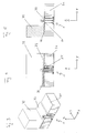
- Fig. 1 shows a connecting device 30 and a fastening device 20 of a first embodiment of an insert 1 according to the invention. This insert 1 is shown in a sectional view in FIG Fig. 2 also shown.
- the connecting device 30 consists of a plate-like elongate central portion 35. At the lower, first end 31 of the connecting device 30, the center piece 35 is in a foot 36 on. At the upper, second end 32 of the connecting device 30 is the fastening device 20, which is designed here as an external thread, wherein the thread is not shown for reasons of clarity.
- the connecting device 30 is connected to a main body 10 of the insert 1 according to the invention.
- the insert 1 according to the invention formed in two pieces. However, it may also be formed in one piece.
- a step 21 is formed in the connecting region between the connecting device 30 and the fastening device 20, a step 21 is formed. This serves to fix a mounted on the fastening device 20, to be fastened object from an upper surface 11 of the base 10 spaced. In the embodiment of the insert 1 according to the invention carried out here, this is realized in such a way that the step 21 is located above the surface 11 of the main body 10. As a result, a distance d between the step 21 and the surface 11 is formed. This distance then defines the distance that the lower surface of the object to be fastened to the surface 11 occupies.
- the insert according to the invention permits a compensation movement in the x-direction, which runs perpendicular to a side face 33 of the middle piece 35.
- the forces acting on the fastening device 20 are transmitted to the connecting device 30, which does not deform in the y-direction. Therefore, the forces are further transmitted to the main body 10 of the insert 1.
- Most inserts 1 according to the invention are embedded or glued into a panel. This means that the forces acting on the main body 10 in the y-direction are accordingly forwarded into the panel.
- the different behavior of the insert according to the invention with forces from the x-direction and the y-direction is achieved by the elongate plate-like design of the middle piece 35 of the connecting device 30.
- the middle piece 35 In the y-direction, the middle piece 35 has a much higher material thickness than in the x-direction. Therefore, it does not deform or only slightly deformed in a force acting on the fastening device 20 in the y-direction.
- the middle piece 35 is deflected in the direction of the force. In other words, by means of the combination of fastening device 20 and connecting device 30, it is possible to at least partially yield the force by avoiding the combination in the direction of the force.
- Fig. 3 is a perspective cut view of a panel 71 is shown, to which a partially shown electronics box 72 is attached by means of the above-described inventive insert 1.
- Many electronics boxes 72 for example, which are qualified by the space authorities, such as ESA or NASA, or other loads to be fastened generally have a fastening flange 73. This has holes to attach the electronics box 72 to a panel 71, which can form, for example, the main body of a satellite.
- the panel 71 and the electronics box 72 are made of the same material or if the two materials used have a similar or identical thermal expansion coefficient, conventional rigid inserts can be used for the attachment. Such inserts are also referred to as threaded inserts.
- the panel 71 is made of a CFRP sandwich structure and the electronics box 72 is made of aluminum or titanium, like most qualified electronic boxes, then these two materials have significant differences in thermal expansion coefficient.
- the electronic box 72 made of aluminum expands much more than the panel 71, which is made of CFRP material.
- average temperature fluctuations of + 180 ° C to -160 ° C are expected.
- CFRP tends to contract at higher temperatures.
- the forces resulting from the different expansions must be suitably absorbed by the connection between the electronics box 72 and the panel 71.
- Rigid inserts are not suitable in this case because they pass on the power, however, depending on the exact design of the panel 71 lead to destruction of the panel.
- FIGS. 4 and 5 are each cuts through the in Fig. 3 shown construction shown.
- the insert 1 with the connecting element 30 which is flexible in the x-direction, but rigid in the y-direction, it is possible to at least partially not transfer the expansion of the electronics box 72 to the panel 71. This is done in such a way that, when force acts on the fastening device 20 in the x-direction, the connecting device 30 is slightly deflected in the direction of this force. Therefore, this is also arranged substantially contactless within an inner space 13 of the base body 10.
- the insert 1 has the step 21, as already explained above.
- the distance d defined by the step 21 and the surface 11 of the main body 10 provides a gap 76 between the underside of the electronics box 72 and the top of the panel 71 FIGS. 3, 4 and 5 can be seen, the attachment means 20, which is provided with an external thread, extends through an opening in the flange 73 of the electronics box 72 and is tightened by a nut.
- the underside of the flange 73 rests on the step 21 formed in the lower region of the fastening device 20.
- the gap 76 can be filled with a heat-conducting medium, for example a flexible graphite foil.
- FIGS. 6 and 7 An alternative embodiment of an insert 100 according to the invention will now be described.
- the insert has a sleeve-like base body 110.
- a fastening device 120 is provided inside the main body 110, which may have an internal thread or a through hole in this embodiment.
- the center axis of the fastening device 120 is coaxial with the central axis of the base body 100.
- the fastening device 120 is fastened to the base body 110 by means of a connecting device 130.
- the connecting device 130 has two substantially parallel webs 131 and 132. These each extend from an inner surface 115 to the opposite inner surface 115 through an inner space 113 of the base body 110. Between the two webs 131 and 132, the fastening device 120 is provided.
- the webs 131 and 132 preferably extend over the entire height of the main body 110, wherein the height is seen in the z-direction.
- the webs 131 and 132 may be formed, for example, as two plate-like elements having the same thickness over their entire height and length. In the embodiment shown here, the webs 131 and 132 have areas of lesser thickness and greater thickness. Of course, it is not absolutely necessary that the webs 131 and 132 are connected to the main body 110 over the entire height.
- connection device 130 Due to the construction according to the invention of the insert 100, it is possible for the connection device 130 to deflect in the x-direction when there is a force acting on the fastening device 120. In other words, the fastening device 120 can move in the x-direction with respect to the main body 110. In contrast, when a force acting on the fastening device 120 in the y-direction, in which the webs 131 and 132 of the connecting device 130 extend, the force is transmitted to the main body 110 of the insert 100. The main body 110 itself transmits the force in turn to the material in which it is embedded.
- the webs 131 and 132 have different thicknesses along their length. This has the consequence that the thinned areas are preweakened as bends and so the deflection is made largely at the thinned areas. In a version with constant Thickness would complete the deflection over the entire length of the webs 131 and 132.
- a force acting in the z-direction on the fastening device 120 is transmitted directly to the webs 131 and 132, which in turn transmit the force to the main body 110 of the insert 100. Analogous to a force in the y direction, this force is then introduced into the material surrounding the insert 100.
- an interior 113 is provided inside the insert 100, in which the fastening device 120 can be displaced and the connection device 130 can be deflected.
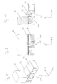
- FIGS. 8, 9 and 10 is now analogous to the FIGS. 3, 4 and 5 the attachment of the electronics box 72 to the panel 71 is shown. Unlike the FIGS. 3, 4 and 5 is this in the FIGS. 8, 9 and 10 realized by means of the insert 100.
- the electronics box 72 in the insert 100 is screwed into the internal thread of the fastening device 120 by means of a screw which has an external thread.
- a spacer 142 may be provided between the underside of the flange 73 and the top of the insert 100.
- the insert 100 Analogous to the use of the insert 1, it is also possible with the insert 100 to compensate for a longitudinal expansion of the electronics box in the x-direction by means of a displacement or movement of the fastening device 120 in the x-direction, which is realized by the connecting device 130. Likewise, forces which act on the fastening device 120 in the y or z direction are forwarded directly into the panel 71 by means of the connection device 130 and the main body 110.
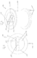
- FIGS. 11 and 12 Another alternative embodiment of an insert 200 according to the invention is shown in FIGS. 11 and 12 shown.
- Fig. 11 turn a supervision
- Fig. 12 a perspective view of the insert 200 according to the invention shown.
- the insert 200 differs from the insert 100 in that, in this embodiment, the fastening device 230 again has two webs 231 and 232, but these do not extend from the inner surface 215 of the main body 210 to the opposite inner surface 215.
- the webs 231 and 232 of the insert 200 are tapered in some area. This has the same result as already described with regard to the insert 100 that a deflection of the connecting device 230 in the x-direction takes place significantly at the tapered or thinned areas. With a design of the webs 231 and 232 with a constant thickness over the entire length, the deflection would take place substantially continuously over the entire length.
- a reinforcement 236 is located in the region of the fastening device 220. This reinforcement increases the absorption of rotational forces which act on the fastening device 220, for example when screwing in and tightening a screw. Such a reinforcement 236 can be dispensed with in the construction of the insert 100, since the webs are connected to the base body in two places.
- the fastening device 220 and the connecting device 230 is provided guideless in the interior 213 except for the attachment of the webs 231 and 232 on the inner surface 215 of the base body 210.
- the insert 200 in turn transmits forces acting on the fastening device 220 in the x-direction, limited only to the base body 210 and thus to the material surrounding the base body 210. A portion of the forces or deflection is absorbed by a displacement of the fastening device 220 and the connecting device 230. Forces acting on the fastening device 220 in the y or z direction are conducted via the connecting device 230 and the main body 210 into the material surrounding the insert 200.
- FIGS. 13 and 14 Another alternative embodiment of an insert 300 according to the invention is shown in FIGS FIGS. 13 and 14 shown. Here is in Fig. 13 turn a supervision and in Fig. 14 a perspective view of the insert 300 according to the invention shown.
- the insert 300 allows movement of a fastener 320 which may be formed as an internal thread or through bore in both the x and y directions.
- a connecting device 330 by means of which the fastening device 320 is fastened to a main body 310 of the insert 300, can be deflected in the x and y directions.
- the connecting device 330 has two partial areas. A first subregion has two webs 331 and 332, which extend in the y direction. The second portion has ridges 333 and 334 extending in the x direction.
- the construction of the webs 331, 332, 333, 334 is similar to that of the webs 131 and 132 of the insert 100.
- the webs 331, 332 extend from an inner surface 315 through the inner space 313 of the main body 310 to the opposite inner surface 315
- the fastening device 320 is not arranged directly on the webs 331, 332, but again a second pair of webs 333, 334, which both extend from the web 331 to the web 332. Only between these further webs 333, 334, the fastening device 320 is provided.
- a reinforcing ring 337 between the first webs 331, 332 and the second webs 333, 334 is provided. But this reinforcing ring 337 is not mandatory.
- the webs 331 and 332 allow movement in this direction.
- a force acting on the fastening device 320 in the y-direction leads to a deflection of the second webs 333, 334. Only a force in the z direction on the fastening device 320 leads to a transmission of force via the connecting device 330 and the base body 320 on the insert 300 surrounding material.
- FIGS. 15 and 16 a further embodiment of an insert 400 according to the invention is shown.
- Fig. 15 turn a supervision
- Fig. 16 a perspective view of the insert 400 according to the invention shown.
- a fastening device 420 In an inner space 413 of the main body 410 is again a fastening device 420. This is fastened by means of a connecting device 430 which extends from the inner surfaces 415 to the fastening device 420.
- the webs which are a part of the connecting device 430, do not run in a straight line here, but form a spiral-like structure. However, they also extend over substantially the entire height of the main body 410.
- the fastening device 420 may in turn be formed as a continuous bore or internal thread. With the construction shown here, a displacement of the fastening device 420 is made possible both in the x-direction and in the y-direction. Forces acting on the fastening device 420 in the z direction can again be conducted via the connecting device 430 and the main body 410 onto the material surrounding the insert 400.
- Fig. 17 a highly simplified view of an electronics box 527 is shown attached to a panel. For reasons of clarity, the panel is not shown here.
- the electronics box 527 has a flange 573. Through holes 573 are provided in the flange 573, by means of which the electronics box 527 with inserts according to the invention is fastened to the panel. In the mounting design shown here inserts are used, which are movable in a spatial direction.
- the insert provided in place 511 is capable of deflection in the direction indicated by the arrows 521, that is, of movement or displacement of the fastening device.
- the insert at location 512 is designed to deflect in the direction 522 and the insert at location 513 to be deflected in the direction 523.
- the inserts are arranged so that the directions 521, 522, 523, in which they are deflected, in a point 551, which is the center of the electronics box 527 in this embodiment meet. But it is not mandatory that this is the center point. It only has to be a point which preferably lies within the peripheral surface of the body to be fastened, for example the electronics box 527.
- the insert is deflected at location 511 in 521 until no further deflection is possible.
- the inserts at locations 512 and 513 readily deflect into their respective deflection directions 522 and 523 and transfer the residual forces into the panel.
- the deflection or movement of the fastening device by the deflection of the connecting device can be understood as the deflection of an insert.
- the expansion as viewed from the central point 551 is uniform in every direction. This means that all inserts at locations 511, 512 and 513 deflect into their respective deflection directions 521, 522 and 523 without completely transferring the forces resulting from the expansion to the panel.
- the insert has been described as being embedded in the panel by default in the above description, it is also possible to provide the insert in the object to be fixed.
Landscapes
- Engineering & Computer Science (AREA)
- General Engineering & Computer Science (AREA)
- Mechanical Engineering (AREA)
- Connection Of Plates (AREA)
Priority Applications (1)
| Application Number | Priority Date | Filing Date | Title |
|---|---|---|---|
| EP13170304.3A EP2811176A1 (fr) | 2013-06-03 | 2013-06-03 | Insert |
Applications Claiming Priority (1)
| Application Number | Priority Date | Filing Date | Title |
|---|---|---|---|
| EP13170304.3A EP2811176A1 (fr) | 2013-06-03 | 2013-06-03 | Insert |
Publications (1)
| Publication Number | Publication Date |
|---|---|
| EP2811176A1 true EP2811176A1 (fr) | 2014-12-10 |
Family
ID=48577540
Family Applications (1)
| Application Number | Title | Priority Date | Filing Date |
|---|---|---|---|
| EP13170304.3A Withdrawn EP2811176A1 (fr) | 2013-06-03 | 2013-06-03 | Insert |
Country Status (1)
| Country | Link |
|---|---|
| EP (1) | EP2811176A1 (fr) |
Cited By (1)
| Publication number | Priority date | Publication date | Assignee | Title |
|---|---|---|---|---|
| US20230400141A1 (en) * | 2022-06-08 | 2023-12-14 | GM Global Technology Operations LLC | System including a thermo-structural spacer for air inlet and compressor interface |
Citations (4)
| Publication number | Priority date | Publication date | Assignee | Title |
|---|---|---|---|---|
| US3416274A (en) * | 1965-10-08 | 1968-12-17 | Nasa | Flexibly connected support and skin |
| EP0547823A1 (fr) * | 1991-12-18 | 1993-06-23 | Raytheon Company | Elément d'assemblage pour compensation des distorsions thermiques |
| JP2002257293A (ja) * | 2001-03-02 | 2002-09-11 | Nec Corp | 1軸拘束型熱応力吸収支持機構 |
| FR2972033A1 (fr) * | 2011-02-24 | 2012-08-31 | Thales Sa | Insert, panneau structural comprenant un tel insert, et procede de montage d'un equipement sur un panneau structural par au moins un insert |
-
2013
- 2013-06-03 EP EP13170304.3A patent/EP2811176A1/fr not_active Withdrawn
Patent Citations (4)
| Publication number | Priority date | Publication date | Assignee | Title |
|---|---|---|---|---|
| US3416274A (en) * | 1965-10-08 | 1968-12-17 | Nasa | Flexibly connected support and skin |
| EP0547823A1 (fr) * | 1991-12-18 | 1993-06-23 | Raytheon Company | Elément d'assemblage pour compensation des distorsions thermiques |
| JP2002257293A (ja) * | 2001-03-02 | 2002-09-11 | Nec Corp | 1軸拘束型熱応力吸収支持機構 |
| FR2972033A1 (fr) * | 2011-02-24 | 2012-08-31 | Thales Sa | Insert, panneau structural comprenant un tel insert, et procede de montage d'un equipement sur un panneau structural par au moins un insert |
Cited By (2)
| Publication number | Priority date | Publication date | Assignee | Title |
|---|---|---|---|---|
| US20230400141A1 (en) * | 2022-06-08 | 2023-12-14 | GM Global Technology Operations LLC | System including a thermo-structural spacer for air inlet and compressor interface |
| US12320465B2 (en) * | 2022-06-08 | 2025-06-03 | GM Global Technology Operations LLC | System including a thermo-structural spacer for air inlet and compressor interface |
Similar Documents
| Publication | Publication Date | Title |
|---|---|---|
| EP2822835B1 (fr) | Colonne de direction pour un véhicule automobile | |
| EP2517282B1 (fr) | Batterie de cellules à production de voltage et un élément en forme de i qu de h interposé | |
| EP2143960B1 (fr) | Dispositif pour maintenir un système de palier | |
| EP3374265B1 (fr) | Dispositif de fixation pour une partie composant à fixer dans une rail dans une structure de plancher d'un avion | |
| EP2888419B1 (fr) | Ensemble de support et construction érigée au moyen dudit ensemble de support | |
| DE2753188A1 (de) | Lasttragkonstruktion fuer einen raumsatelliten | |
| EP2030891A2 (fr) | Avion doté d'un fuselage et d'une structure de sol | |
| EP3464013A1 (fr) | Liaison entre des pièces présentant des coefficients de dilatation thermique différents | |
| EP1730416A1 (fr) | Palier en caoutchouc, notamment pour un organe motopompe de direction assistee | |
| EP1577211A2 (fr) | Dispositif de fixation d'une unité à un aéronef | |
| DE102013205275B3 (de) | Flugzeugrumpfstruktur | |
| DE102014204087A1 (de) | Halter zur Anbindung eines Bauteils an eine Komponente eines Luft- oder Raumfahrzeugs, Anordnung, Luft- oder Raumfahrzeug, sowie Verfahren | |
| DE102013011378A1 (de) | Rahmen für einen Flugkörper | |
| EP2180197A2 (fr) | Ecrou spécial | |
| EP2698295B1 (fr) | Tube télescopique réglable en longueur, béquille télescopique et procédé de montage | |
| DE102018131608A1 (de) | Lenksystem mit einer Justierungsanordnung | |
| DE102013225605A1 (de) | Anordnung von Batteriemodulen in einem Batterietrog | |
| EP2887513A2 (fr) | Système de moteur linéaire et machine-outil dotée d'un système de moteur linéaire | |
| DE60300352T2 (de) | Vorrichtung zur Befestigung eines Landefahrwerks auf eine Flugzeugstruktur | |
| WO2017081128A1 (fr) | Dispositif de fixation pour un élément destiné à être fixé dans des rails d'une structure de plancher d'une cabine d'aéronef | |
| DE102009028529A1 (de) | Tragschienenvorrichtung zum Tragen eines Moduls eines Luft- und Raumfahrzeugs | |
| EP0449001B1 (fr) | Joint universel sans jeu et sans friction | |
| DE102007061804B4 (de) | Verbindungselement zur Verbindung von zwei Bauteilen | |
| DE102015122675A1 (de) | Sicherungsvorrichtung und Linearführungsmechanismus | |
| EP2599944A1 (fr) | Support de cadre de fenêtre |
Legal Events
| Date | Code | Title | Description |
|---|---|---|---|
| PUAI | Public reference made under article 153(3) epc to a published international application that has entered the european phase |
Free format text: ORIGINAL CODE: 0009012 |
|
| 17P | Request for examination filed |
Effective date: 20130603 |
|
| AK | Designated contracting states |
Kind code of ref document: A1 Designated state(s): AL AT BE BG CH CY CZ DE DK EE ES FI FR GB GR HR HU IE IS IT LI LT LU LV MC MK MT NL NO PL PT RO RS SE SI SK SM TR |
|
| AX | Request for extension of the european patent |
Extension state: BA ME |
|
| STAA | Information on the status of an ep patent application or granted ep patent |
Free format text: STATUS: THE APPLICATION IS DEEMED TO BE WITHDRAWN |
|
| 18D | Application deemed to be withdrawn |
Effective date: 20150611 |