EP2811187A1 - Linear guide device - Google Patents
Linear guide device Download PDFInfo
- Publication number
- EP2811187A1 EP2811187A1 EP20120867027 EP12867027A EP2811187A1 EP 2811187 A1 EP2811187 A1 EP 2811187A1 EP 20120867027 EP20120867027 EP 20120867027 EP 12867027 A EP12867027 A EP 12867027A EP 2811187 A1 EP2811187 A1 EP 2811187A1
- Authority
- EP
- European Patent Office
- Prior art keywords
- end cap
- trunk
- face
- plate
- rolling
- Prior art date
- Legal status (The legal status is an assumption and is not a legal conclusion. Google has not performed a legal analysis and makes no representation as to the accuracy of the status listed.)
- Granted
Links
- 238000005096 rolling process Methods 0.000 claims description 59
- 239000000314 lubricant Substances 0.000 claims description 17
- 230000008021 deposition Effects 0.000 claims description 4
- 229920003002 synthetic resin Polymers 0.000 claims description 4
- 239000000057 synthetic resin Substances 0.000 claims description 4
- 230000008878 coupling Effects 0.000 description 4
- 238000010168 coupling process Methods 0.000 description 4
- 238000005859 coupling reaction Methods 0.000 description 4
- 230000000149 penetrating effect Effects 0.000 description 3
- 229920005989 resin Polymers 0.000 description 3
- 239000011347 resin Substances 0.000 description 3
- 230000008602 contraction Effects 0.000 description 2
- 125000006850 spacer group Chemical group 0.000 description 2
- 230000000694 effects Effects 0.000 description 1
- 239000004519 grease Substances 0.000 description 1
- 238000001746 injection moulding Methods 0.000 description 1
- 210000002445 nipple Anatomy 0.000 description 1
- 239000000243 solution Substances 0.000 description 1
Images


Classifications
-
- F—MECHANICAL ENGINEERING; LIGHTING; HEATING; WEAPONS; BLASTING
- F16—ENGINEERING ELEMENTS AND UNITS; GENERAL MEASURES FOR PRODUCING AND MAINTAINING EFFECTIVE FUNCTIONING OF MACHINES OR INSTALLATIONS; THERMAL INSULATION IN GENERAL
- F16C—SHAFTS; FLEXIBLE SHAFTS; ELEMENTS OR CRANKSHAFT MECHANISMS; ROTARY BODIES OTHER THAN GEARING ELEMENTS; BEARINGS
- F16C33/00—Parts of bearings; Special methods for making bearings or parts thereof
- F16C33/30—Parts of ball or roller bearings
- F16C33/66—Special parts or details in view of lubrication
- F16C33/6637—Special parts or details in view of lubrication with liquid lubricant
- F16C33/6659—Details of supply of the liquid to the bearing, e.g. passages or nozzles
-
- F—MECHANICAL ENGINEERING; LIGHTING; HEATING; WEAPONS; BLASTING
- F16—ENGINEERING ELEMENTS AND UNITS; GENERAL MEASURES FOR PRODUCING AND MAINTAINING EFFECTIVE FUNCTIONING OF MACHINES OR INSTALLATIONS; THERMAL INSULATION IN GENERAL
- F16C—SHAFTS; FLEXIBLE SHAFTS; ELEMENTS OR CRANKSHAFT MECHANISMS; ROTARY BODIES OTHER THAN GEARING ELEMENTS; BEARINGS
- F16C29/00—Bearings for parts moving only linearly
- F16C29/04—Ball or roller bearings
- F16C29/06—Ball or roller bearings in which the rolling bodies circulate partly without carrying load
- F16C29/0602—Details of the bearing body or carriage or parts thereof, e.g. methods for manufacturing or assembly
- F16C29/0604—Details of the bearing body or carriage or parts thereof, e.g. methods for manufacturing or assembly of the load bearing section
- F16C29/0607—Details of the bearing body or carriage or parts thereof, e.g. methods for manufacturing or assembly of the load bearing section of parts or members for retaining the rolling elements, i.e. members to prevent the rolling elements from falling out of the bearing body or carriage
-
- F—MECHANICAL ENGINEERING; LIGHTING; HEATING; WEAPONS; BLASTING
- F16—ENGINEERING ELEMENTS AND UNITS; GENERAL MEASURES FOR PRODUCING AND MAINTAINING EFFECTIVE FUNCTIONING OF MACHINES OR INSTALLATIONS; THERMAL INSULATION IN GENERAL
- F16C—SHAFTS; FLEXIBLE SHAFTS; ELEMENTS OR CRANKSHAFT MECHANISMS; ROTARY BODIES OTHER THAN GEARING ELEMENTS; BEARINGS
- F16C29/00—Bearings for parts moving only linearly
- F16C29/04—Ball or roller bearings
- F16C29/06—Ball or roller bearings in which the rolling bodies circulate partly without carrying load
- F16C29/0602—Details of the bearing body or carriage or parts thereof, e.g. methods for manufacturing or assembly
- F16C29/0609—Details of the bearing body or carriage or parts thereof, e.g. methods for manufacturing or assembly of the ends of the bearing body or carriage where the rolling elements change direction, e.g. end caps
-
- F—MECHANICAL ENGINEERING; LIGHTING; HEATING; WEAPONS; BLASTING
- F16—ENGINEERING ELEMENTS AND UNITS; GENERAL MEASURES FOR PRODUCING AND MAINTAINING EFFECTIVE FUNCTIONING OF MACHINES OR INSTALLATIONS; THERMAL INSULATION IN GENERAL
- F16C—SHAFTS; FLEXIBLE SHAFTS; ELEMENTS OR CRANKSHAFT MECHANISMS; ROTARY BODIES OTHER THAN GEARING ELEMENTS; BEARINGS
- F16C29/00—Bearings for parts moving only linearly
- F16C29/04—Ball or roller bearings
- F16C29/06—Ball or roller bearings in which the rolling bodies circulate partly without carrying load
- F16C29/0633—Ball or roller bearings in which the rolling bodies circulate partly without carrying load with a bearing body defining a U-shaped carriage, i.e. surrounding a guide rail or track on three sides
- F16C29/0635—Ball or roller bearings in which the rolling bodies circulate partly without carrying load with a bearing body defining a U-shaped carriage, i.e. surrounding a guide rail or track on three sides whereby the return paths are provided as bores in a main body of the U-shaped carriage, e.g. the main body of the U-shaped carriage is a single part with end caps provided at each end
- F16C29/0638—Ball or roller bearings in which the rolling bodies circulate partly without carrying load with a bearing body defining a U-shaped carriage, i.e. surrounding a guide rail or track on three sides whereby the return paths are provided as bores in a main body of the U-shaped carriage, e.g. the main body of the U-shaped carriage is a single part with end caps provided at each end with balls
- F16C29/0642—Ball or roller bearings in which the rolling bodies circulate partly without carrying load with a bearing body defining a U-shaped carriage, i.e. surrounding a guide rail or track on three sides whereby the return paths are provided as bores in a main body of the U-shaped carriage, e.g. the main body of the U-shaped carriage is a single part with end caps provided at each end with balls with four rows of balls
- F16C29/0647—Ball or roller bearings in which the rolling bodies circulate partly without carrying load with a bearing body defining a U-shaped carriage, i.e. surrounding a guide rail or track on three sides whereby the return paths are provided as bores in a main body of the U-shaped carriage, e.g. the main body of the U-shaped carriage is a single part with end caps provided at each end with balls with four rows of balls with load directions in X-arrangement
-
- F—MECHANICAL ENGINEERING; LIGHTING; HEATING; WEAPONS; BLASTING
- F16—ENGINEERING ELEMENTS AND UNITS; GENERAL MEASURES FOR PRODUCING AND MAINTAINING EFFECTIVE FUNCTIONING OF MACHINES OR INSTALLATIONS; THERMAL INSULATION IN GENERAL
- F16C—SHAFTS; FLEXIBLE SHAFTS; ELEMENTS OR CRANKSHAFT MECHANISMS; ROTARY BODIES OTHER THAN GEARING ELEMENTS; BEARINGS
- F16C29/00—Bearings for parts moving only linearly
- F16C29/08—Arrangements for covering or protecting the ways
- F16C29/084—Arrangements for covering or protecting the ways fixed to the carriage or bearing body movable along the guide rail or track
- F16C29/086—Seals being essentially U-shaped, e.g. for a U-shaped carriage
-
- F—MECHANICAL ENGINEERING; LIGHTING; HEATING; WEAPONS; BLASTING
- F16—ENGINEERING ELEMENTS AND UNITS; GENERAL MEASURES FOR PRODUCING AND MAINTAINING EFFECTIVE FUNCTIONING OF MACHINES OR INSTALLATIONS; THERMAL INSULATION IN GENERAL
- F16C—SHAFTS; FLEXIBLE SHAFTS; ELEMENTS OR CRANKSHAFT MECHANISMS; ROTARY BODIES OTHER THAN GEARING ELEMENTS; BEARINGS
- F16C29/00—Bearings for parts moving only linearly
- F16C29/04—Ball or roller bearings
- F16C29/06—Ball or roller bearings in which the rolling bodies circulate partly without carrying load
- F16C29/0633—Ball or roller bearings in which the rolling bodies circulate partly without carrying load with a bearing body defining a U-shaped carriage, i.e. surrounding a guide rail or track on three sides
- F16C29/0652—Ball or roller bearings in which the rolling bodies circulate partly without carrying load with a bearing body defining a U-shaped carriage, i.e. surrounding a guide rail or track on three sides whereby the return paths are at least partly defined by separate parts, e.g. covers attached to the legs of the main body of the U-shaped carriage
- F16C29/0654—Ball or roller bearings in which the rolling bodies circulate partly without carrying load with a bearing body defining a U-shaped carriage, i.e. surrounding a guide rail or track on three sides whereby the return paths are at least partly defined by separate parts, e.g. covers attached to the legs of the main body of the U-shaped carriage with balls
- F16C29/0659—Ball or roller bearings in which the rolling bodies circulate partly without carrying load with a bearing body defining a U-shaped carriage, i.e. surrounding a guide rail or track on three sides whereby the return paths are at least partly defined by separate parts, e.g. covers attached to the legs of the main body of the U-shaped carriage with balls with four rows of balls
Definitions
- the present invention relates to a linear guide apparatus.
- the linear guide apparatus is provided with a guide rail, a slider, and plural rolling elements.
- the guide rail and the slider include rolling grooves (or rolling faces when the rolling elements are “rollers"), respectively, disposed opposing each other and forming a rolling passage of the rolling elements.
- the slider further includes a return passage of the rolling elements and a direction changing path for communicating the return passage with the rolling passage.
- a circulation path of the rolling elements is configured with the rolling passage, the return passage, and the direction changing path.
- the linear guide apparatus is provided with separators, each of the separator including a spacer disposed between adjacent rolling elements and an arm portion (i.e., guide portion) secured to the spacer and extending in an arrangement direction of the rolling elements, and a guide groove to guide the arm portion is formed in the circulation path of the rolling elements, in some cases.
- the rolling elements move through the circulation path with being held or accommodated in the separators, and the arm portions of the separators moves along the guide groove.
- the slider is configured with a body (i e., block body), a resin circulation path forming body, and an end cap (i.e., side cover).
- the body is configured with leg portions respectively arranged on both sides in a width direction of the guide rail, and a trunk portion to connect both of the leg portions, and the rolling grooves are respectively formed on the inner sides of the leg portions.
- PLT 1 discloses that a member (i.e., resin frame) is provided for each of the leg portions, the member being integrally formed of a retaining portion for retaining the rolling elements on the rolling face (i.e., load ball passage configuring portion extending along both side rims of the rolling groove), an inner circumference guiding portion (i.e., return guide) of the direction changing path, and a plate-shaped portion to be brought into contact with both end faces of each of the leg portions. Additionally, the end cap is secured to the end face of the body via the plate-shaped portion. Further, in the end cap, an accommodating recess portion for accommodating the plate-shaped portion is formed in a uniform depth. PLT 1, however, does not disclose the plate-shaped portion being provided with an oil supply path forming groove for forming an oil path between the plate-shaped portion and the end cap
- PLT 2 discloses a retainer being provided for each of the leg portions of the slider body, the retainer being integrated with the plate-shaped portion to be brought into contact with both end faces of the body (except for a central portion in the width direction of the trunk portion), and a retaining portion disposed on the inner face of each of the leg portions and retaining the rolling elements on the rolling face, and the oil supply path forming groove is provided on an end cap side face of the plate-shaped portion.
- an oil supply opening penetrating through the end cap in a thickness direction at the central portion of the trunk portion of the end cap, and the oil supply path forming groove extending to both sides of the oil supply opening is formed on an abutting face abutting with the slider body.
- a face lower than the abutting face is formed as a disposition face of the plate-shaped portion of the retaining portion. Accordingly, by securing the end cap to the body on which the retainer is attached, the plate-shaped portion of the retainer is disposed on a plate-shaped portion disposition face of the end cap, so that the oil supply path forming groove of the end cap and the oil supply path forming groove of the plate-shaped portion are communicated with each other to form an oil supply path from an oil supply opening to the direction changing path.
- a lubricant is made to hardly leak from between the end cap and the slider body.
- a linear guide apparatus comprising the following configurations (a) to (e):
- a pair of retainers satisfying the above configuration (2) are provided and the plate-shaped portion satisfies the above configurations (c) to (e), so that the lubricant existing in the oil path can be hardly leaked regardless of the relationship of the interval between the plate-shaped portion deposition face and the abutting face (i.e., the face to be brought into contact with the slider body) of the end cap and the thickness of the plate-shaped portion of the retainer. That is, even if the interval between the deposition face and the abutting face of the end cap is smaller than the thickness of the plate-shaped portion, the lubricant existing in the oil path can be hardly leaked.
- the oil supply opening penetrates through the end cap in the thickness direction of the end cap and is connected with the oil groove of the plate-shaped portion
- the opposing or contacting position of the end faces of the adjacent trunk parts i.e., the end faces of the trunk parts of both of the retainers
- the position is set not to overlap the oil supply opening, thereby eliminating such a measure.
- the opposing or contacting position of the end faces of the adjacent trunk parts should be set to the position of not overlapping the oil supply opening.
- the lengths of the trunk parts are made smaller than the length in which the both ends contacts with each other and the widths of the recess portion and the projection portion of the trunk parts (i.e., size in the thickness direction of the trunk portion of the slider body) are made so that the recess portion and the projection portion of the trunk parts are brought into contact with each other or oppose each other with a slight gap.
- the lubricant can be hardly leaked from between both of the end faces. Since the widths of the trunk parts are smaller in size than the lengths of the trunk parts, the contraction quantity of the synthetic resin in the trunk part is smaller in the width direction than that in the length direction" Therefore, the size management becomes easy.
- the lubricant can be hardly leaked from between both end faces more certainly.
- a lubricant can be hardly leaked from between the end cap and the slider body, regardless of a relationship of an interval between a plate-shaped portion disposition face and an abutting face (i.e., a face abutting with the slider body) of the end cap and the thickness of the plate-shaped portion in the retainer.
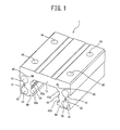
- FIG. 1 is a perspective view illustrative of a body of a slider included in the linear guide apparatus according to the present embodiment.
- FIG. 2 is a perspective view illustrative of one of a pair of retainers included in the linear guide apparatus according to the present embodiment.
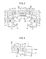
- FIG. 3 is a front view illustrative of a state in which a pair of retainers are attached to the body illustrated in FIG. 1
- FIG. 4 is a partially enlarged view of FIG. 3 .
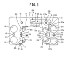
- FIG. 5 is a partial sectional view of FIG. 3 , illustrating with one of the retainers being cut away.
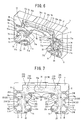
- FIG. 6 is a perspective view illustrative of a body side face of an end cap of the slider included in the linear guide apparatus according to the present embodiment.
- FIG. 7 is a view illustrative of an overlapping state of the end cap of FIG. 6 and the retainer of FIG 2 .
- the slider according to the present embodiment includes a body 1, a pair of retainers 2A and 2B, a return guide 3, and an end cap 7.
- the body 1 of the slider includes leg portions 11 and 12 disposed on both sides in the width direction of the guide rail, respectively, and a trunk portion 13 connecting both of the leg portions 11 and 12.
- Each of the leg portions 11 and 12 has two through holes 41 for two return passages, respectively, a screw hole 42 formed between the two through holes 41 so as to attach an end cap, and two rows of rolling grooves (rolling faces) 43a and 43b each having an arc-shaped cross section on an inner face.
- a groove 44 having an arc-shaped cross section is also formed between both of the rolling grooves 43a and 43b.
- Screw holes 45 are formed on an end face of the trunk portion 13 of the body 1 so as to attach the end cap.
- Screw holes 46 are formed on a top face of the trunk portion 13 so as to attach the slider to another member.
- recess portions 48 are respectively arranged on the lower ends of both of the leg portions 11 and 12 of the body 1, so as to attach an underseal.
- retainers 2A and 2B are respectively provided for the leg portions 11 and 12 of the body 1.
- the retainers 2A and 2B include two plate-shaped portions 21A and two plate-shaped portions 21B, respectively.
- Each of the retainers 2A and 2B include an upper retaining portion 22a, a middle retaining portion 22b, a lower retaining portion 22c, a flange portion 24, a sleeve portion 25, and coupling portions 26, respectively.
- FIG. 2 partially illustrates the left-side retainer 2A and entirely illustrates the right-side retainer 2B, but the left-side retainer 2A is same as the right-side 2B except for the shape of a part of the plate-shaped portion 21A.
- the plate-shaped portions 21A and 21B include leg portions 211 disposed to conform to the leg portions 11 and 12 of the body 1.
- the plate-shaped portions 21A and 21B include trunk parts 212A and 212B disposed to conform to the trunk portions 13, respectively
- An upper recess portion 213 and a lower recess portion 217 are formed on the inner side in the width direction of each of the leg portions 211.
- Two through holes 218 communicating with the two through holes 41 of each of the leg portions 11 and 12 of the body 1 and a through hole 219 communicating with the screw hole 42 of each of the leg portions 11 and 12 of the body 1 are formed on the outer side in the width direction of the leg portions 211.
- Through holes 212a communicating with the screw holes 45 of the trunk portion 13 of the body 1 are formed in the trunk parts 212A and 212B, respectively.
- the trunk part 212A of the retainer 2A for the leg portion 11 is longer than the trunk part 212B of the retainer 2B for the leg portion 12, and extends to the right side of the center (i.e., locations of an oil supply opening 70 and a joint attachment hole 70a of the end cap 7, as will be described later) in the width direction of the trunk portion 13 of the body 1.
- a projection portion 212c is formed on an end face of the trunk part 212A of the retainer 2A.
- a recess portion 212d to be fitted by the projection portion 212c is arranged on an end face of the trunk part 212B of the retainer 2B.
- FIG. 4 is an enlarged view illustrative of this part.
- the lengths of the trunk parts 212A and 212B are made slightly shorter than the length in which both end faces come in contact with each other, and the width of the projection portion 212c of the trunk part 212A and the recess portion 212d of the trunk part 212B (i.e., the size in the thickness direction of the trunk portion 13 of the body 1) are made so that the projection portion 212c of the trunk part 212A and the recess portion 212d of the trunk part 212B are brought into contact with each other.
- an oil groove 23 made to conform to an oil groove 76, to be described later, formed in the end cap 7 is formed on an end cap side face of the plate-shaped portions 21A and 21B.
- the oil groove 23 includes circular grooves 23a on the outer side of the through hole 212a, straight grooves 23b extending inward along the trunk parts 212A and 212B from the circular grooves 23a, angular grooves 23c extending outward from the circular grooves 23a, and long grooves 23d extending to the leg portions from the angular grooves 23c.
- the long grooves 23d respectively extend between the through hole 218 and the upper recess portion 213, and also extend between the through hole 218 and the lower recess portion 217.
- the two plate-shaped portions 21A and the two plate-shaped portions 21B are respectively spaced apart from each other by a distance corresponding to the distance between the end faces of the body 1.
- the flange portion 24, the upper retaining portion 22a, the middle retaining portion 22b, the lower retaining portion 22c, and the sleeve portion 25 are provided from the trunk portion 13 side, and integrated together.
- the sleeve portion 25 and the lower retaining portion 22c are coupled by the coupling portion 26, such that the retainers 2A and 2B respectively have integrated shapes formed by injection molding of a synthetic resign.
- FIG. 5 is a view illustrative of the plate-shaped portion 21A of the left-side retainer 2A in which the leg portion side is cut along a contact plane to be in contact with both end faces of the body 1.
- the upper retaining portions 22a, the middle retaining portions 22b, and the lower retaining portions 22c are arranged on the inner face of the body 1 and serve as members to cause the two rows of rolling grooves 43a and 43b to hold balls (i.e., the rolling elements) in each of the leg portions 11 and 12.
- the flange portion 24 is interposed between the trunk portion 13 and the guide rail and serves as a member to be arranged on the lower face of the trunk portion 13.
- the sleeve portion 25 is a member of forming a recess portion 27, for attaching the underseal, between the sleeve portion 25 and a recess portion 48 of the body 1.
- a separator having an arm portion is arranged between adjacent balls for circulating the balls, the slider is provided with guide slots 5 to guide the arm portions.
- the guide slots 5 are configured with inner faces continuous with the rolling grooves 43a and 43b of the leg portions 11 and 12 of the body 1, and recess portions 221a to 224a, extending entirely in the length direction of the slider, provided in the retaining portions 22a to 22c of each of the retainers 2A and 2B.
- the upper retaining portion 22a is arranged on top of the upper rolling groove 43a, and includes an arc-shaped ball retaining face 221 to conform to the diameters of the balls, and a recess portion 221a continuous with the ball retaining face 221 made to conform to the diameters of the balls.
- the flange portion 24 is integrated with the upper retaining portion 22a.
- the middle retaining portion 22b is arranged at a groove 44 between the upper and lower rolling grooves 43a and 43b, and includes recess portions 222a and 223a continuous with the upper and lower ball retaining faces 222 and 223, respectively.
- the lower retaining portion 22c is arranged at bottom of the lower rolling groove 43b, and includes an arc-shaped ball retaining face 224 made to conform to the diameters of the balls, and a recess portion 224a continuous with the ball retaining face 224.
- the oil supply opening 70 penetrating in the thickness direction of the end cap 7 is formed at the center of the trunk portion of the end cap 7.
- two recess portions 71 forming an outer circumferential guide face of the direction changing path are formed on a body side face of the end cap 7 in each of the leg portions, and through holes 72 for the attachment bolts to penetrate therethrough are arranged between the upper and lower recess portions 71, respectively,
- through holes 73 are also formed at locations conforming to the screw holes 45 of the trunk portion 13 of the body 1, respectively, Furthermore, recess portions 74 to be fitted by edge portions 31 of the return guide 3 and a recess portion 75 to be fitted by a coupling portion 32 of the return guide 3 are formed in the end cap 7.
- a part (i.e., disposition face) 7A in which the plate-shaped portions 21A and 21B of the retainers 2A and 2B are deposited is lower than an abutting face (i.e., contact face to be brought into contact with an end face of the body 1) 7B by the thickness of the plate-shaped portion 21A or 21B.
- edge portions 71a and 71b protruding at a height equal to or higher than the abutting face 7B from the disposition face 7A are provided around the recess portions 71, respectively, End faces in the length direction of the upper retaining portion 22a and the lower retaining portion 22c of the retainers 2A and 2B are arranged on a protruding face (flush with the abutting face 7B) of the edge portion 71b.
- a face 71c on which the intermediate retaining portion 22b is arranged is as high as the disposition face 7A.
- the disposition face 7A of the end cap 7 is provided with the oil groove 76 extending from the oil supply opening 70 to the recess portions 71 on both sides.
- the oil groove 76 is configured with circular grooves 76a on the outer side of the through holes 73, straight grooves 76b extending in a linear shape leftward and rightward (outward in the width direction) from the oil supply opening 70 to reach the circular grooves 76a, respectively, angular grooves 76c extending outward from the circular grooves 76a, and longitudinal grooves 76d extending toward the recess portions 71 from the angular grooves 76c.
- the oil groove 76 is formed at the location where the trunk parts 212A and 212B of the plate-shaped portion 21 are to be arranged.
- grooves 33 continuous with the oil grooves 76d are formed in the return guide 3.
- Oil supply holes 34 penetrating through the return guide 3 are formed at locations respectively conforming to the recess portions 71 of the groove 33.
- FIG. 7 is a view illustrative of the slider after the slider is assembled, in which the body 1 is omitted and the retainers 2A and 2B are cut just before the plate-shaped portions 21A and 21B, and the end cap 7 side is viewed.
- a joint attachment hole 70a is arranged at a location of the oil supply opening 70 of the end cap 7.
- the joint attachment hole 70a extends to a partway in the thickness direction from a face opposing the disposition face 7A of the end cap 7, and communicates with the oil supply opening 70.
- the retainers 2A and 2B are firstly attached to the body 1 of the slider from the inner side of each of the leg portions 11 and 12, and the plate-shaped portions 21A and 21B are arranged on both end faces of the body 1.
- the return guide 3 and the end cap 7 are deposited at one end face of the body 1.
- the screw holes 42 of the body 1, the through holes 219 of the plate-shaped portions 21A and 21B, and the through holes 72 of the end cap 7 are respectively aligned with each other, and the screw holes 45 of the body 1, the through holes 212a of the plate-shaped portions 21A and 21B, and the through hole 73 of the end cap 7 are respectively aligned with each other.
- the end cap 7 is attached to the body 1 by bolts or small screws.
- the plate-shaped portions 21A and 21B of the retainers 2A and 2B are disposed on the disposition face 7A of the end cap 7, as illustrated in FIG. 7 .
- An oil path is configured with the oil groove 76 of the end cap 7, the oil groove 33 of the return guide 3, and the oil groove 23 of the plate-shaped portions 21A and 21B overlapping the oil groove 33.
- the upper and lower direction changing paths are configured with the upper and lower recess portions 71 in the return guide 3 and the end cap 7.
- the guide slots 5 are respectively formed in the direction changing path by the return guide 3 and the edge portions 71a of the recess portions 71.
- a return passage is formed in the body 1 by inserting a sleeve or the like having the guide slot or guide face to guide the arm portion of the separator having the arm portion, into the through hole 41 of the body 1.
- Both leg portions of the slider are disposed on both sides in the width direction of the guide rail by sliding and moving the slider assembled in this manner from an end portion of the guide rail
- the balls are arranged in the rolling passage configured with the rolling grooves 43a and 43b of the slider and the rolling groove of the guide rail.
- the lubricant introduced from the oil supply opening 70 passes through the oil path configured with the oil grooves 23 formed in the plate-shaped portions 21A and 21B of the retainers 2A and 2B, and the oil grooves 76 and 33 of the end cap 7 and return guide 3, so as to be supplied to the direction changing path from the oil supply hole 34 of the return guide 3.
- a grease nipple or the like i.e., lubricant supplying pipe
- trunk parts 212A and 212B of the retainers 2A and 2B cover a central portion in the width direction of the trunk portion 13 on each end face of the body 1, in the whole width direction. Furthermore, end faces of both trunk parts 212A and 212B are fitted to each other at the projection portion 212c and the recess portion 212d to be brought into contact with each other in the width direction of the projection portion 212c and the recess portion 212d (i.e., in the thickness direction of the trunk portion 13 of the body 1), and a slight gap is made in the length direction of the retainers 2A and 2B (i.e., in the width direction of the slider)
- the end faces of the trunk parts 212A and 212B of the retainers 2A and 2B oppose each other at a central portion in the width direction of the trunk portion 13 on each end face of the body 1.
- the end faces of the adjacent trunk parts 212A and 212B oppose each other at a location of not overlapping the oil supply opening 70
- the lubricant in the oil path can be hardly leaked.
- the interval between the disposition face 7A and the abutting face 7B of the end cap 7 is smaller than the thickness of the plate-shaped portions 21A and 21B of the retainers 2A and 2B, the lubricant in the oil path can be hardly leaked.
- the oil grooves of the plate-shaped portions 21A and 21B of the retainers 2A and 2B are formed to overlap the oil grooves formed in the end cap 7 and the return guide 3.
- the retainers 2A and 2B illustrated in FIG. 9 are used.
- the recess portion 74 to be fitted by edge portions 31 of the return guide 3 and the recess portion 75 to be fitted by the coupling portion 32 of the return guide 3 are formed in the end cap 7 of FIG. 8 , in a similar manner to FIG. 6 .
- the oil grooves 77 and 78 are formed to vertically interpose the oil supply opening 70.
- the upper oil groove 77 linearly extends leftward and rightward above the oil supply opening 70, forms arc shapes on the upper side of the through hole 73, and then turns downward at right angle to reach oil reservoirs 77a, respectively.
- the lower oil groove 78 linearly extends leftward and rightward below the oil supply opening 70, forms arc shapes on the lower side of the through hole 73, extends laterally a little, and then turns downward at right angle to reach the recess portions 71, respectively. Also in the end cap 7 of FIG. 8 , the return guides 3 configured in a similar manner to FIG. 6 are fitted into the recess portions 74 and 75 for use, respectively, so that the groove 33 of the return guide 3 continues with the lower oil groove 78.
- an oil groove 28 to overlap the oil grooves 77 and 78 of the end cap 7, the oil supply opening 70, and the groove 33 of the return guide 3 is formed in the plate-shaped portions 21A and 21B of the retainers 2A and 2B.
- the oil groove 28 includes a part 28a to overlap the oil supply opening 70, a part 28b to overlap the upper oil groove 77, a part 28c to overlap the lower oil groove 78, and a part 28d to overlap the groove 33 of the return guide 3
- the parts 28b and 28c to respectively overlap the upper and lower oil grooves 77 and 78 are coupled with the part 28a to overlap the oil supply opening 70.
- the trunk part 212A of the retainer 2A for the leg portion 11 is longer than the trunk part 212B of the retainer 2B for the leg portion 12, and extends to the right side of the center (i.e., the locations of the oil supply opening 70 and the joint attachment hole 70a of the end cap 7) in the width direction of the trunk portion 13 of the body 1.
- Recess portions 212e are formed at locations of the respective oil grooves 28b and 28c on the end face of the trunk part 212A of the retainer 2A.
- Projection portions 212f to be fitted into the respective recess portions 212e are formed on the end face of the trunk part 212B of the retainer 2B
- FIG. 10 is an enlarged view illustrative of this part.
- the lengths of the trunk parts 212A and 212B are slightly made shorter than a size with which both end faces are brought into contact, and the widths of the recess portions 212e of the trunk part 212A and the proj ection portions 212f of the trunk part 212B (i.e., the size in the thickness direction of the trunk portion 13 of the body 1) are made to have the sizes to contact with each other
- a projection is provided on one of the end faces to project from the one of the end face, whereas the other of the end faces of the trunk portion is made flat, so that the projection may be elastically deformed by contacting with the flat face at the time of attachment, As compared with the case where such a projection is not provided, even if the dimensional tolerance is not strict very much, the lubricant can be hardly leaked from between both end faces.
- FIG. 11 is a partially enlarged view of a front view illustrative of a state where the retainers 2A and 2B are attached to the body.
- FIG. 12 is a view illustrative of an end face of the trunk part 212A of the retainer 2A.
- protrusions 212g protruding from the end faces of the trunk part 212A are provided at end faces of the trunk part 212A, whereas an end face 212h of the trunk part 212B is made flat.
- the protrusions 212g are formed on the end faces of the trunk part 212A at both ends in the width direction.
- the protrusions 212g become an elastically deformed state by contacting with the flat face 212h at the time of attachment.
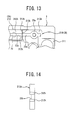
- FIG. 13 is a partially enlarged view of a front view illustrative of a state where the retainers 2A and 2B are attached to the body.
- FIG. 14 is a view illustrative of an end face of the trunk part 212A of the retainer 2A.
- projections 212k projecting from the end faces of the trunk part 212A are provided at the trunk part 212A, whereas the end face 212h of the trunk part 212B is made flat.
- the projections 212k are formed on both end faces of an oil groove 23b of the trunk part 212A.
- the projections 212k become an elastically deformed state by contacting with the flat face 212h at the time of attachment.
- each of the above embodiments has been described is an example in which the end faces of adjacent trunk parts 212A and 212B oppose each other or contact with each other at a location of not overlapping the oil supply opening 70.
- the lubricant can be hardly leaked as compared to the configuration of the PLT 2.
- the end faces of adjacent trunk parts 212A and 212B are both flat faces, the lubricant can be hardly leaked as compared to the configuration of the PLT 2.
Landscapes
- Engineering & Computer Science (AREA)
- General Engineering & Computer Science (AREA)
- Mechanical Engineering (AREA)
- Bearings For Parts Moving Linearly (AREA)
Abstract
Description
- The present invention relates to a linear guide apparatus.
- The linear guide apparatus is provided with a guide rail, a slider, and plural rolling elements. The guide rail and the slider include rolling grooves (or rolling faces when the rolling elements are "rollers"), respectively, disposed opposing each other and forming a rolling passage of the rolling elements. The slider further includes a return passage of the rolling elements and a direction changing path for communicating the return passage with the rolling passage Then, a circulation path of the rolling elements is configured with the rolling passage, the return passage, and the direction changing path. By circulation of the rolling elements through the circulation path, one of the guide rail and the slider is relatively and linearly moved to the other thereof.
- In addition, the linear guide apparatus is provided with separators, each of the separator including a spacer disposed between adjacent rolling elements and an arm portion (i.e., guide portion) secured to the spacer and extending in an arrangement direction of the rolling elements, and a guide groove to guide the arm portion is formed in the circulation path of the rolling elements, in some cases. In such cases, the rolling elements move through the circulation path with being held or accommodated in the separators, and the arm portions of the separators moves along the guide groove.
-
PLT 1 discloses that the slider is configured with a body (i e., block body), a resin circulation path forming body, and an end cap (i.e., side cover). The body is configured with leg portions respectively arranged on both sides in a width direction of the guide rail, and a trunk portion to connect both of the leg portions, and the rolling grooves are respectively formed on the inner sides of the leg portions. - As the resin circulation path forming body,
PLT 1 discloses that a member (i.e., resin frame) is provided for each of the leg portions, the member being integrally formed of a retaining portion for retaining the rolling elements on the rolling face (i.e., load ball passage configuring portion extending along both side rims of the rolling groove), an inner circumference guiding portion (i.e., return guide) of the direction changing path, and a plate-shaped portion to be brought into contact with both end faces of each of the leg portions. Additionally, the end cap is secured to the end face of the body via the plate-shaped portion. Further, in the end cap, an accommodating recess portion for accommodating the plate-shaped portion is formed in a uniform depth.PLT 1, however, does not disclose the plate-shaped portion being provided with an oil supply path forming groove for forming an oil path between the plate-shaped portion and the end cap - PLT 2 discloses a retainer being provided for each of the leg portions of the slider body, the retainer being integrated with the plate-shaped portion to be brought into contact with both end faces of the body (except for a central portion in the width direction of the trunk portion), and a retaining portion disposed on the inner face of each of the leg portions and retaining the rolling elements on the rolling face, and the oil supply path forming groove is provided on an end cap side face of the plate-shaped portion. In addition, an oil supply opening penetrating through the end cap in a thickness direction at the central portion of the trunk portion of the end cap, and the oil supply path forming groove extending to both sides of the oil supply opening is formed on an abutting face abutting with the slider body.
- Furthermore, on a body side face of the end cap, a face lower than the abutting face is formed as a disposition face of the plate-shaped portion of the retaining portion. Accordingly, by securing the end cap to the body on which the retainer is attached, the plate-shaped portion of the retainer is disposed on a plate-shaped portion disposition face of the end cap, so that the oil supply path forming groove of the end cap and the oil supply path forming groove of the plate-shaped portion are communicated with each other to form an oil supply path from an oil supply opening to the direction changing path.
- In the configuration of PLT 2, however, when an interval between the plate-shaped portion disposition face of the end cap and the abutting face is smaller than the thickness of the plate-shaped portion of the retainer, a gap is generated at a location where the plate-shaped portion is not present between the end cap and the trunk portion of the body. Hence, the lubricant easily leaks.
-
- PLT 1: FIG. 40 to FIG. 44 of
JP Patent No. 3,571,911 - PLT 2:
JP 2008-138748 A - It is an object of the present invention to provide a linear guide apparatus in which a plate-shaped portion having an oil supply groove and being in contact with an end face of the slider body is integrally formed with a retainer, and the plate-shaped portion is disposed between the end face of the slider body and an end cap. In the linear guide apparatus, regardless of a relationship of an interval between a plate-shaped portion disposition face and an abutting face of the end cap (i.e., a face abutting with the slider body) and the thickness of the plate-shaped portion of the retainer, a lubricant is made to hardly leak from between the end cap and the slider body.
- In order to address the above object, there is provided a linear guide apparatus, comprising the following configurations (a) to (e):
- (a) a guide rail; a slider; and a plurality of rolling elements, wherein the guide rail and the slider are configured to form rolling faces disposed to oppose each other for forming a rolling passage of the plurality of rolling elements, the slider includes a return passage of the plurality of rolling elements, and a direction changing path for communicating the return passage and the rolling passage, a circulation path of the plurality of rolling elements is configured with the rolling passage, the return passage, and the direction changing path, the guide rail or the slider are configured to relatively move linearly with respect to each other, by the plurality of rolling elements circulating in the circulation path,
- (b) the slider comprises: (1) a body including a pair of leg portions arranged on both sides in a width direction of the guide rail and a trunk portion connecting the pair of leg portions, the rolling faces being respectively formed on inner sides of the pair of leg portions, (2) a pair of retainers made of a synthetic resin and respectively arranged for the pair of leg portions, the pair of retainers being integrally formed with plate-shaped portions to be in contact with both of end faces of the body and a holding portion arranged on an inner face of each of the pair of leg portions and holding the plurality of rolling elements on the rolling faces, (3) an end cap including an oil supply opening to be connected with a lubricant supplying pipe, a recess portion forming an outer circumference of the direction changing path on a body side face of the end cap, and a deposition face of the plate-shaped portion lower than an abutting face to be in contact with the body, the end cap being secured to either of both of the end faces of the body, and (4) a return guide of forming an inner circumference of the direction changing path.
- (c) an oil groove configured to form an oil path from the oil supply opening to the recess portion between the plate-shaped portion and the end cap, the oil groove being arranged on an end cap side face of the plate-shaped portion.
- (d) the plate-shaped portion includes a leg part to be in contact with one of the pair of leg portions and a trunk part to be in contact with a part of the trunk portion.
- (e) end faces of the trunk parts of the pair of retainers oppose each other or contact with each other at a central portion in a width direction of the trunk portion of each of the end faces of the body.
- According to the linear guide apparatus in one aspect of the present invention, a pair of retainers satisfying the above configuration (2) are provided and the plate-shaped portion satisfies the above configurations (c) to (e), so that the lubricant existing in the oil path can be hardly leaked regardless of the relationship of the interval between the plate-shaped portion deposition face and the abutting face (i.e., the face to be brought into contact with the slider body) of the end cap and the thickness of the plate-shaped portion of the retainer. That is, even if the interval between the deposition face and the abutting face of the end cap is smaller than the thickness of the plate-shaped portion, the lubricant existing in the oil path can be hardly leaked.
- In a case where the oil supply opening penetrates through the end cap in the thickness direction of the end cap and is connected with the oil groove of the plate-shaped portion, when the opposing or contacting position of the end faces of the adjacent trunk parts (i.e., the end faces of the trunk parts of both of the retainers) is set to the position of overlapping the oil supply opening, a measure should be taken for changing the size or the like of the oil supply opening so that the lubricant can be hardly leaked. However, the position is set not to overlap the oil supply opening, thereby eliminating such a measure.
- Accordingly, in the case where the oil supply opening penetrates through the end cap in the thickness direction of the end cap and is connected with the oil groove of the plate-shaped portion of the retainer, it is desirable that the opposing or contacting position of the end faces of the adjacent trunk parts should be set to the position of not overlapping the oil supply opening.
- In addition, in a case where the end faces of the adjacent trunk parts are both flat, even if the retainer is produced with the dimensional tolerance being strict for contact between both of the end faces, it may be difficult to obtain the retainer with a gap between both of the end faces being completely zero because of contraction or the like of a synthetic resin. In particular, in a case where the sizes of the adjacent trunk part (i.e., size in the width direction of the slider) both deviate to a larger one, it may be impossible not only to contact the end faces, but also to attach the retainer correctly.
- In contrast, in a case where the end faces of the adjacent trunk parts have the recess portion and the projection portion to fit with each other, the lengths of the trunk parts are made smaller than the length in which the both ends contacts with each other and the widths of the recess portion and the projection portion of the trunk parts (i.e., size in the thickness direction of the trunk portion of the slider body) are made so that the recess portion and the projection portion of the trunk parts are brought into contact with each other or oppose each other with a slight gap. Hence, the lubricant can be hardly leaked from between both of the end faces. Since the widths of the trunk parts are smaller in size than the lengths of the trunk parts, the contraction quantity of the synthetic resin in the trunk part is smaller in the width direction than that in the length direction" Therefore, the size management becomes easy.
- Accordingly, in the case where the end faces of the adjacent trunk parts have the recess portion and the projection portion to fit with each other, as compared to a case where the end faces are both flat, the lubricant can be hardly leaked from between both end faces more certainly.
- According to the linear guide apparatus of the present invention, a lubricant can be hardly leaked from between the end cap and the slider body, regardless of a relationship of an interval between a plate-shaped portion disposition face and an abutting face (i.e., a face abutting with the slider body) of the end cap and the thickness of the plate-shaped portion in the retainer.
-
-
FIG. 1 is a perspective view illustrative of a body included in a slider according to an embodiment of the present invention; -
FIG.. 2 is a perspective view illustrative of a retainer according to an embodiment of the present invention; -
FIG. 3 is a front view illustrative of a state in which a pair of retainers are attached to the body of the slider; -
FIG. 4 is a partially enlarged view ofFIG. 3 ; -
FIG. 5 is a partial sectional view ofFIG 3 , illustrating with one of the retainers being cut away; -
FIG. 6 is a perspective view illustrative of an end cap included in the slider according to an embodiment of the present invention; -
FIG. 7 is a view illustrative of an overlapping state of the end cap and a pair of retainers; -
FIG. 8 is a front view illustrative of the end cap with another oil path pattern; -
FIG. 9 is a front view illustrative of a state in which a retainer for the end cap ofFIG. 8 is attached to the slider body; -
FIG. 10 is a partially enlarged view ofFIG. 9 ; -
FIG 11 is a view illustrative of an example of a relationship between end faces of adjacent trunk portions; -
FIG. 12 is a view illustrative of an end face of a trunk part on the left side ofFIG. 11 ; -
FIG. 13 is a view illustrative of an example of a relationship between end faces of adjacent trunk parts; and -
FIG. 14 is a view illustrative of an end face of the trunk part on the left side ofFIG. 13 . - Hereinafter, embodiments of the present invention will be described, but the present invention is not limited to the embodiments.
-
FIG. 1 is a perspective view illustrative of a body of a slider included in the linear guide apparatus according to the present embodiment.FIG. 2 is a perspective view illustrative of one of a pair of retainers included in the linear guide apparatus according to the present embodiment.FIG. 3 is a front view illustrative of a state in which a pair of retainers are attached to the body illustrated inFIG. 1 , andFIG. 4 is a partially enlarged view ofFIG. 3 .FIG. 5 is a partial sectional view ofFIG. 3 , illustrating with one of the retainers being cut away. -
FIG. 6 is a perspective view illustrative of a body side face of an end cap of the slider included in the linear guide apparatus according to the present embodiment.FIG. 7 is a view illustrative of an overlapping state of the end cap ofFIG. 6 and the retainer ofFIG 2 . - As illustrated in these figures, the slider according to the present embodiment includes a
body 1, a pair ofretainers return guide 3, and anend cap 7. - Referring to
FIG. 1 , thebody 1 of the slider includesleg portions trunk portion 13 connecting both of theleg portions leg portions holes 41 for two return passages, respectively, ascrew hole 42 formed between the two throughholes 41 so as to attach an end cap, and two rows of rolling grooves (rolling faces) 43a and 43b each having an arc-shaped cross section on an inner face. Agroove 44 having an arc-shaped cross section is also formed between both of the rollinggrooves - Screw holes 45 are formed on an end face of the
trunk portion 13 of thebody 1 so as to attach the end cap. Screw holes 46 are formed on a top face of thetrunk portion 13 so as to attach the slider to another member. In addition,recess portions 48 are respectively arranged on the lower ends of both of theleg portions body 1, so as to attach an underseal. - As illustrated in
FIG. 3 ,retainers leg portions body 1. Theretainers FIG. 2 andFIG. 3 , include two plate-shapedportions 21A and two plate-shapedportions 21B, respectively. Each of theretainers upper retaining portion 22a, amiddle retaining portion 22b, alower retaining portion 22c, aflange portion 24, asleeve portion 25, andcoupling portions 26, respectively.FIG. 2 partially illustrates the left-side retainer 2A and entirely illustrates the right-side retainer 2B, but the left-side retainer 2A is same as the right-side 2B except for the shape of a part of the plate-shapedportion 21A. - The plate-shaped
portions leg portions 211 disposed to conform to theleg portions body 1. The plate-shapedportions trunk parts trunk portions 13, respectively Anupper recess portion 213 and alower recess portion 217 are formed on the inner side in the width direction of each of theleg portions 211. Two throughholes 218 communicating with the two throughholes 41 of each of theleg portions body 1 and a throughhole 219 communicating with thescrew hole 42 of each of theleg portions body 1 are formed on the outer side in the width direction of theleg portions 211. Throughholes 212a communicating with the screw holes 45 of thetrunk portion 13 of thebody 1 are formed in thetrunk parts - In addition, the
trunk part 212A of theretainer 2A for the leg portion 11 (left side ofFIG. 3 ) is longer than thetrunk part 212B of theretainer 2B for theleg portion 12, and extends to the right side of the center (i.e., locations of anoil supply opening 70 and ajoint attachment hole 70a of theend cap 7, as will be described later) in the width direction of thetrunk portion 13 of thebody 1. Aprojection portion 212c is formed on an end face of thetrunk part 212A of theretainer 2A. Arecess portion 212d to be fitted by theprojection portion 212c is arranged on an end face of thetrunk part 212B of theretainer 2B.FIG. 4 is an enlarged view illustrative of this part. - As illustrated in
FIG. 4 , the lengths of thetrunk parts projection portion 212c of thetrunk part 212A and therecess portion 212d of thetrunk part 212B (i.e., the size in the thickness direction of thetrunk portion 13 of the body 1) are made so that theprojection portion 212c of thetrunk part 212A and therecess portion 212d of thetrunk part 212B are brought into contact with each other. - Further, an
oil groove 23 made to conform to anoil groove 76, to be described later, formed in theend cap 7 is formed on an end cap side face of the plate-shapedportions oil groove 23 includescircular grooves 23a on the outer side of the throughhole 212a,straight grooves 23b extending inward along thetrunk parts circular grooves 23a,angular grooves 23c extending outward from thecircular grooves 23a, andlong grooves 23d extending to the leg portions from theangular grooves 23c. Thelong grooves 23d respectively extend between the throughhole 218 and theupper recess portion 213, and also extend between the throughhole 218 and thelower recess portion 217. - Regarding the
retainers portions 21A and the two plate-shapedportions 21B are respectively spaced apart from each other by a distance corresponding to the distance between the end faces of thebody 1. Between the two plate-shapedportions flange portion 24, theupper retaining portion 22a, themiddle retaining portion 22b, thelower retaining portion 22c, and thesleeve portion 25 are provided from thetrunk portion 13 side, and integrated together. Moreover, thesleeve portion 25 and thelower retaining portion 22c are coupled by thecoupling portion 26, such that theretainers -
FIG. 5 is a view illustrative of the plate-shapedportion 21A of the left-side retainer 2A in which the leg portion side is cut along a contact plane to be in contact with both end faces of thebody 1. - As can be seen from
FIG. 5 , theupper retaining portions 22a, themiddle retaining portions 22b, and thelower retaining portions 22c are arranged on the inner face of thebody 1 and serve as members to cause the two rows of rollinggrooves leg portions flange portion 24 is interposed between thetrunk portion 13 and the guide rail and serves as a member to be arranged on the lower face of thetrunk portion 13. Thesleeve portion 25 is a member of forming arecess portion 27, for attaching the underseal, between thesleeve portion 25 and arecess portion 48 of thebody 1. - According to the linear guide apparatus of the present embodiment, a separator having an arm portion is arranged between adjacent balls for circulating the balls, the slider is provided with
guide slots 5 to guide the arm portions. In other words, as illustrated inFIG. 5 , theguide slots 5 are configured with inner faces continuous with the rollinggrooves leg portions body 1, andrecess portions 221a to 224a, extending entirely in the length direction of the slider, provided in the retainingportions 22a to 22c of each of theretainers - The
upper retaining portion 22a is arranged on top of theupper rolling groove 43a, and includes an arc-shapedball retaining face 221 to conform to the diameters of the balls, and arecess portion 221a continuous with theball retaining face 221 made to conform to the diameters of the balls. Theflange portion 24 is integrated with theupper retaining portion 22a. Themiddle retaining portion 22b is arranged at agroove 44 between the upper and lower rollinggrooves recess portions lower retaining portion 22c is arranged at bottom of thelower rolling groove 43b, and includes an arc-shapedball retaining face 224 made to conform to the diameters of the balls, and arecess portion 224a continuous with theball retaining face 224. - As illustrated in
FIG. 6 , theoil supply opening 70 penetrating in the thickness direction of theend cap 7 is formed at the center of the trunk portion of theend cap 7. In addition, tworecess portions 71 forming an outer circumferential guide face of the direction changing path are formed on a body side face of theend cap 7 in each of the leg portions, and throughholes 72 for the attachment bolts to penetrate therethrough are arranged between the upper andlower recess portions 71, respectively, - In the
end cap 7, throughholes 73 are also formed at locations conforming to the screw holes 45 of thetrunk portion 13 of thebody 1, respectively, Furthermore,recess portions 74 to be fitted byedge portions 31 of thereturn guide 3 and arecess portion 75 to be fitted by acoupling portion 32 of thereturn guide 3 are formed in theend cap 7. - On the body side face of the
end cap 7, a part (i.e., disposition face) 7A in which the plate-shapedportions retainers portion - Therefore,
edge portions abutting face 7B from thedisposition face 7A are provided around therecess portions 71, respectively, End faces in the length direction of theupper retaining portion 22a and thelower retaining portion 22c of theretainers abutting face 7B) of theedge portion 71b. Aface 71c on which theintermediate retaining portion 22b is arranged is as high as thedisposition face 7A. - Furthermore, the
disposition face 7A of theend cap 7 is provided with theoil groove 76 extending from theoil supply opening 70 to therecess portions 71 on both sides. Theoil groove 76 is configured withcircular grooves 76a on the outer side of the throughholes 73,straight grooves 76b extending in a linear shape leftward and rightward (outward in the width direction) from theoil supply opening 70 to reach thecircular grooves 76a, respectively, angular grooves 76c extending outward from thecircular grooves 76a, andlongitudinal grooves 76d extending toward therecess portions 71 from the angular grooves 76c. - In other words, the
oil groove 76 is formed at the location where thetrunk parts grooves 33 continuous with theoil grooves 76d are formed in thereturn guide 3. Oil supply holes 34 penetrating through thereturn guide 3 are formed at locations respectively conforming to therecess portions 71 of thegroove 33. -
FIG. 7 is a view illustrative of the slider after the slider is assembled, in which thebody 1 is omitted and theretainers portions end cap 7 side is viewed. As illustrated inFIG. 7 , ajoint attachment hole 70a is arranged at a location of theoil supply opening 70 of theend cap 7. Thejoint attachment hole 70a extends to a partway in the thickness direction from a face opposing thedisposition face 7A of theend cap 7, and communicates with theoil supply opening 70. - When the linear guide apparatus according to the present embodiment is assembled, the
retainers body 1 of the slider from the inner side of each of theleg portions portions body 1. - Subsequently, the
return guide 3 and theend cap 7 are deposited at one end face of thebody 1. The screw holes 42 of thebody 1, the throughholes 219 of the plate-shapedportions holes 72 of theend cap 7 are respectively aligned with each other, and the screw holes 45 of thebody 1, the throughholes 212a of the plate-shapedportions hole 73 of theend cap 7 are respectively aligned with each other. Then, theend cap 7 is attached to thebody 1 by bolts or small screws. - By such attachment, the plate-shaped
portions retainers disposition face 7A of theend cap 7, as illustrated inFIG. 7 . An oil path is configured with theoil groove 76 of theend cap 7, theoil groove 33 of thereturn guide 3, and theoil groove 23 of the plate-shapedportions oil groove 33. In addition, the upper and lower direction changing paths are configured with the upper andlower recess portions 71 in thereturn guide 3 and theend cap 7. Furthermore, theguide slots 5 are respectively formed in the direction changing path by thereturn guide 3 and theedge portions 71a of therecess portions 71. - Next, although not illustrated, a return passage is formed in the
body 1 by inserting a sleeve or the like having the guide slot or guide face to guide the arm portion of the separator having the arm portion, into the throughhole 41 of thebody 1. - After that, from an end (the other end face side) to which the
end cap 7 of thebody 1 is not attached, balls and the separators having the arm portions are alternately entered in the direction changing path configured with the rolling passage, the return passage, and theend cap 7 and thereturn guide 3 attached to thebody 1. Then, the balls and separators having the arm portions are alternately entered in the direction changing path configured with theother end cap 7 and thereturn guide 3, and theend cap 7, and then thereturn guide 3 are secured to the other end face of thebody 1 in the similar manner as described above. In this manner, an oil path configured with theoil grooves oil groove 23 is formed at the other end part of the slider. - Both leg portions of the slider are disposed on both sides in the width direction of the guide rail by sliding and moving the slider assembled in this manner from an end portion of the guide rail Thus, the balls are arranged in the rolling passage configured with the rolling
grooves - In the linear guide apparatus according to the present embodiment, by connecting a grease nipple or the like (i.e., lubricant supplying pipe) with the
joint attachment hole 70a, the lubricant introduced from theoil supply opening 70 passes through the oil path configured with theoil grooves 23 formed in the plate-shapedportions retainers oil grooves end cap 7 and returnguide 3, so as to be supplied to the direction changing path from theoil supply hole 34 of thereturn guide 3. - Additionally, the
trunk parts retainers trunk portion 13 on each end face of thebody 1, in the whole width direction. Furthermore, end faces of bothtrunk parts projection portion 212c and therecess portion 212d to be brought into contact with each other in the width direction of theprojection portion 212c and therecess portion 212d (i.e., in the thickness direction of thetrunk portion 13 of the body 1), and a slight gap is made in the length direction of theretainers trunk parts retainers trunk portion 13 on each end face of thebody 1. Moreover, the end faces of theadjacent trunk parts oil supply opening 70. - Accordingly, regardless of the relationship of the interval between the
disposition face 7A and theabutting face 7B of theend cap 7 and the thickness of the plate-shapedportions retainers disposition face 7A and theabutting face 7B of theend cap 7 is smaller than the thickness of the plate-shapedportions retainers - The oil grooves of the plate-shaped
portions retainers end cap 7 and thereturn guide 3. When theend cap 7 ofFIG. 8 is used, for example, theretainers FIG. 9 are used. - The
recess portion 74 to be fitted byedge portions 31 of thereturn guide 3 and therecess portion 75 to be fitted by thecoupling portion 32 of thereturn guide 3 are formed in theend cap 7 ofFIG. 8 , in a similar manner toFIG. 6 . In addition, theoil grooves oil supply opening 70. Theupper oil groove 77 linearly extends leftward and rightward above theoil supply opening 70, forms arc shapes on the upper side of the throughhole 73, and then turns downward at right angle to reachoil reservoirs 77a, respectively. - The
lower oil groove 78 linearly extends leftward and rightward below theoil supply opening 70, forms arc shapes on the lower side of the throughhole 73, extends laterally a little, and then turns downward at right angle to reach therecess portions 71, respectively. Also in theend cap 7 ofFIG. 8 , the return guides 3 configured in a similar manner toFIG. 6 are fitted into therecess portions groove 33 of thereturn guide 3 continues with thelower oil groove 78. - As illustrated in
FIG. 9 , anoil groove 28 to overlap theoil grooves end cap 7, theoil supply opening 70, and thegroove 33 of thereturn guide 3 is formed in the plate-shapedportions retainers oil groove 28 includes apart 28a to overlap theoil supply opening 70, apart 28b to overlap theupper oil groove 77, apart 28c to overlap thelower oil groove 78, and apart 28d to overlap thegroove 33 of thereturn guide 3 Theparts lower oil grooves part 28a to overlap theoil supply opening 70. - In addition, the
trunk part 212A of theretainer 2A for the leg portion 11 (illustrated on the left side inFIG. 9 ) is longer than thetrunk part 212B of theretainer 2B for theleg portion 12, and extends to the right side of the center (i.e., the locations of theoil supply opening 70 and thejoint attachment hole 70a of the end cap 7) in the width direction of thetrunk portion 13 of thebody 1.Recess portions 212e are formed at locations of therespective oil grooves trunk part 212A of theretainer 2A.Projection portions 212f to be fitted into therespective recess portions 212e are formed on the end face of thetrunk part 212B of theretainer 2BFIG. 10 is an enlarged view illustrative of this part. - As illustrated in
FIG. 10 , the lengths of thetrunk parts recess portions 212e of thetrunk part 212A and the proj ectionportions 212f of thetrunk part 212B (i.e., the size in the thickness direction of thetrunk portion 13 of the body 1) are made to have the sizes to contact with each other - As to the end faces of both
trunk parts retainers -
FIG. 11 is a partially enlarged view of a front view illustrative of a state where theretainers FIG. 12 is a view illustrative of an end face of thetrunk part 212A of theretainer 2A. - In this example,
protrusions 212g protruding from the end faces of thetrunk part 212A are provided at end faces of thetrunk part 212A, whereas anend face 212h of thetrunk part 212B is made flat. Theprotrusions 212g are formed on the end faces of thetrunk part 212A at both ends in the width direction. Theprotrusions 212g become an elastically deformed state by contacting with theflat face 212h at the time of attachment. -
FIG. 13 is a partially enlarged view of a front view illustrative of a state where theretainers FIG. 14 is a view illustrative of an end face of thetrunk part 212A of theretainer 2A. - In this example,
projections 212k projecting from the end faces of thetrunk part 212A are provided at thetrunk part 212A, whereas theend face 212h of thetrunk part 212B is made flat. Theprojections 212k are formed on both end faces of anoil groove 23b of thetrunk part 212A. Theprojections 212k become an elastically deformed state by contacting with theflat face 212h at the time of attachment. - It is to be noted that each of the above embodiments has been described is an example in which the end faces of
adjacent trunk parts oil supply opening 70. However, even if the end faces ofadjacent trunk parts oil supply opening 70, the lubricant can be hardly leaked as compared to the configuration of the PLT 2. In addition, even if the end faces ofadjacent trunk parts -
- 1
- body of slider
- 11, 12
- leg portion of body
- 13
- trunk portion of body
- 2A, 2B
- retainer
- 21A, 21B
- plate-shaped portion of retainer
- 211
- leg part of plate-shaped portion
- 212A, 212B
- trunk part of plate-shaped portion
- 212c
- projection portion arranged on end face of trunk part
- 212d
- recess portion arranged on end face of trunk part
- 212e
- recess portion arranged on end face of trunk part
- 212f
- projection portion arranged on end face of trunk part
- 22a
- upper retaining portion of retainer
- 22b
- middle retaining portion of retainer
- 22c
- lower retaining portion of retainer
- 23
- oil groove of plate-shaped portion
- 28
- oil groove of plate-shaped portion
- 3
- return guide
- 33
- oil groove of return guide
- 43a, 43b
- rolling groove
- 7
- end cap
- 7A
- part on which plate-shaped portion is disposed (disposition face)
- 7B
- abutting face (face to brought into contact with end face of body)
- 70
- oil supply opening
- 71
- recess portion forming outer circumference of direction changing path
- 76
- oil groove of end cap
- 77
- oil groove of end cap
- 78
- oil groove of end cap
Claims (3)
- A linear guide apparatus, comprising:a guide rail;a slider; anda plurality of rolling elements, whereinthe guide rail and the slider are configured to form rolling faces disposed to oppose each other for forming a rolling passage of the plurality of rolling elements,the slider includes a return passage of the plurality of rolling elements, and a direction changing path for communicating the return passage and the rolling passage,a circulation path of the plurality of rolling elements is configured with the rolling passage, the return passage, and the direction changing path,the guide rail or the slider are configured to relatively move linearly with respect to each other, by the plurality of rolling elements circulating in the circulation path,the slider comprises:(1) a body including a pair of leg portions arranged on both sides in a width direction of the guide rail and a trunk portion connecting the pair of leg portions, the rolling faces being respectively formed on inner sides of the pair of leg portions,(2) a pair of retainers made of a synthetic resin and respectively arranged for the pair of leg portions, the pair of retainers being integrally formed with plate-shaped portions to be in contact with both of end faces of the body and a holding portion arranged on an inner face of each of the pair of leg portions and holding the plurality of rolling elements on the rolling faces,(3) an end cap including an oil supply opening to be connected with a lubricant supplying pipe, a recess portion forming an outer circumference of the direction changing path on a body side face of the end cap, and a deposition face of the plate-shaped portion lower than an abutting face to be in contact with the body, the end cap being secured to either of both of the end faces of the body, and(4) a return guide of forming an inner circumference of the direction changing path,an oil groove configured to form an oil path from the oil supply opening to the recess portion between the plate-shaped portion and the end cap, the oil groove being arranged on an end cap side face of the plate-shaped portion,the plate-shaped portion includes a leg part to be in contact with one of the pair of leg portions and a trunk part to be in contact with a part of the trunk portion, andend faces of the trunk parts of the pair of retainers oppose each other or contact with each other at a central portion in a width direction of the trunk portion of each of the end faces of the body.
- The linear guide apparatus according to claim 1, wherein
the oil supply opening is configured to penetrate through the end cap in a thickness direction of the end cap and to be connected to an oil groove of the plate-shaped portion of the retainer, and
the end faces of adjacent trunk parts oppose each other or contact with each other at a position of not overlapping the oil supply opening. - The linear guide apparatus according to claim 1, further comprising a recess portion and a projection portion to fit the end faces of adjacent trunk parts with each other.
Applications Claiming Priority (2)
| Application Number | Priority Date | Filing Date | Title |
|---|---|---|---|
| JP2012018404A JP5724894B2 (en) | 2012-01-31 | 2012-01-31 | Linear guide device |
| PCT/JP2012/005108 WO2013114475A1 (en) | 2012-01-31 | 2012-08-10 | Linear guide device |
Publications (3)
| Publication Number | Publication Date |
|---|---|
| EP2811187A1 true EP2811187A1 (en) | 2014-12-10 |
| EP2811187A4 EP2811187A4 (en) | 2016-02-24 |
| EP2811187B1 EP2811187B1 (en) | 2019-03-20 |
Family
ID=48904565
Family Applications (1)
| Application Number | Title | Priority Date | Filing Date |
|---|---|---|---|
| EP12867027.0A Not-in-force EP2811187B1 (en) | 2012-01-31 | 2012-08-10 | Linear guide device |
Country Status (6)
| Country | Link |
|---|---|
| US (1) | US9068601B2 (en) |
| EP (1) | EP2811187B1 (en) |
| JP (1) | JP5724894B2 (en) |
| CN (1) | CN104081069B (en) |
| TW (1) | TWI518260B (en) |
| WO (1) | WO2013114475A1 (en) |
Cited By (1)
| Publication number | Priority date | Publication date | Assignee | Title |
|---|---|---|---|---|
| EP3351814A4 (en) * | 2015-09-18 | 2018-09-05 | NSK Ltd. | Linear motion guide device and end cap for linear motion guide device |
Families Citing this family (19)
| Publication number | Priority date | Publication date | Assignee | Title |
|---|---|---|---|---|
| JP6424383B2 (en) * | 2014-04-23 | 2018-11-21 | Thk株式会社 | Exercise equipment |
| JP6162641B2 (en) * | 2014-05-15 | 2017-07-12 | Thk株式会社 | Exercise equipment |
| DE102014210171A1 (en) * | 2014-05-28 | 2015-12-17 | Robert Bosch Gmbh | Carriage with mounting hole, which is part of a lubricant flow path |
| USD748705S1 (en) * | 2014-06-30 | 2016-02-02 | Nsk Ltd. | Linear guide |
| JP6030690B1 (en) * | 2015-04-09 | 2016-11-24 | Thk株式会社 | Exercise guidance device |
| CN106812796B (en) * | 2015-11-27 | 2019-11-12 | Thk株式会社 | Motion guide device |
| JP6945980B2 (en) * | 2016-08-31 | 2021-10-06 | 日本トムソン株式会社 | How to load the rolling element into the bending rolling guide unit and its slider |
| JP6494692B2 (en) | 2017-05-31 | 2019-04-03 | Thk株式会社 | Exercise guidance device |
| JP6895811B2 (en) * | 2017-06-02 | 2021-06-30 | 日本トムソン株式会社 | Linear guidance unit |
| AU201817738S (en) * | 2018-06-25 | 2019-01-30 | Radia S R L | Linear guide |
| CN113187814B (en) * | 2021-03-19 | 2023-07-21 | 丽水市杰祥科技有限公司 | Sliding block with smooth roller sliding and assembling method thereof |
| CN113202868B (en) * | 2021-03-19 | 2023-07-21 | 丽水市杰祥科技有限公司 | Sliding block adapting to short stroke |
| TWI769806B (en) * | 2021-05-03 | 2022-07-01 | 東佑達自動化科技股份有限公司 | Compound screw slide table |
| CN113187824B (en) * | 2021-05-08 | 2023-05-16 | 丽水市杰祥科技有限公司 | Linear slider convenient to automatic ball |
| CN113202867B (en) * | 2021-05-08 | 2023-04-14 | 丽水市杰祥科技有限公司 | Integrated retainer for linear module |
| CN113864332B (en) * | 2021-09-18 | 2025-10-17 | 宁波海迈克精密机械制造有限公司 | Rolling linear guide rail pair with integrated ball circulation retaining structure |
| TWI806551B (en) * | 2022-04-15 | 2023-06-21 | 精浚科技股份有限公司 | Linear guideway, sliding module thereof, and circulation seat thereof |
| US11933359B1 (en) * | 2022-08-30 | 2024-03-19 | Hiwin Technologies Corp. | Miniature linear guideway |
| CN117189777B (en) * | 2023-11-06 | 2024-02-20 | 江苏恒立精密工业有限公司 | Precise roller linear guide rail |
Family Cites Families (15)
| Publication number | Priority date | Publication date | Assignee | Title |
|---|---|---|---|---|
| JP3571911B2 (en) * | 1997-06-16 | 2004-09-29 | Thk株式会社 | Linear motion guide device |
| US6132093A (en) * | 1997-06-16 | 2000-10-17 | Thk, Co., Ltd. | Linear motion guiding apparatus |
| US6170986B1 (en) * | 1999-04-07 | 2001-01-09 | Chieftech Precision Co., Ltd. | Linear motion rolling guide device |
| JP4304087B2 (en) * | 2004-01-21 | 2009-07-29 | 上銀科技股▲分▼有限公司 | Linear guideway lubrication system |
| JP4565545B2 (en) * | 2004-03-24 | 2010-10-20 | 日本トムソン株式会社 | Linear motion guidance unit |
| JP4609180B2 (en) * | 2005-05-12 | 2011-01-12 | 日本精工株式会社 | Linear motion guide device |
| JP2007239829A (en) * | 2006-03-07 | 2007-09-20 | Nsk Ltd | Linear guide device |
| JP2008002660A (en) * | 2006-06-26 | 2008-01-10 | Nsk Ltd | Linear guide |
| TWI290984B (en) | 2006-07-04 | 2007-12-11 | Advanced Motion Technologies C | Slide device of linear guide |
| JP4584888B2 (en) * | 2006-09-27 | 2010-11-24 | 日本トムソン株式会社 | Linear motion guidance unit |
| US20080103028A1 (en) * | 2006-11-01 | 2008-05-01 | Advanced Motion Technologies Corp. | Slider for a linear slide system |
| JP2008138748A (en) * | 2006-11-30 | 2008-06-19 | Nsk Ltd | Linear motion guide device |
| DE102006062105B4 (en) * | 2006-12-23 | 2010-12-02 | Precision Motion Industries Inc., Shen Kang Hsiang | Slider for a sliding system |
| JP5272350B2 (en) * | 2007-08-21 | 2013-08-28 | 日本精工株式会社 | Linear motion guide device |
| JP5853581B2 (en) * | 2011-10-21 | 2016-02-09 | 日本精工株式会社 | Linear motion device |
-
2012
- 2012-01-31 JP JP2012018404A patent/JP5724894B2/en active Active
- 2012-08-10 WO PCT/JP2012/005108 patent/WO2013114475A1/en not_active Ceased
- 2012-08-10 US US14/375,642 patent/US9068601B2/en active Active
- 2012-08-10 EP EP12867027.0A patent/EP2811187B1/en not_active Not-in-force
- 2012-08-10 CN CN201280068630.1A patent/CN104081069B/en active Active
- 2012-08-20 TW TW101130112A patent/TWI518260B/en not_active IP Right Cessation
Cited By (2)
| Publication number | Priority date | Publication date | Assignee | Title |
|---|---|---|---|---|
| EP3351814A4 (en) * | 2015-09-18 | 2018-09-05 | NSK Ltd. | Linear motion guide device and end cap for linear motion guide device |
| US10364841B2 (en) | 2015-09-18 | 2019-07-30 | Nsk Ltd. | Linear motion guide device and end cap for linear motion guide device |
Also Published As
| Publication number | Publication date |
|---|---|
| US9068601B2 (en) | 2015-06-30 |
| TW201331488A (en) | 2013-08-01 |
| JP5724894B2 (en) | 2015-05-27 |
| EP2811187A4 (en) | 2016-02-24 |
| EP2811187B1 (en) | 2019-03-20 |
| US20150023618A1 (en) | 2015-01-22 |
| WO2013114475A1 (en) | 2013-08-08 |
| JP2013155832A (en) | 2013-08-15 |
| TWI518260B (en) | 2016-01-21 |
| CN104081069B (en) | 2016-11-02 |
| CN104081069A (en) | 2014-10-01 |
Similar Documents
| Publication | Publication Date | Title |
|---|---|---|
| EP2811187B1 (en) | Linear guide device | |
| KR100713041B1 (en) | Linear motion guidance device | |
| US9284988B2 (en) | Guide device | |
| US8858082B2 (en) | Circulation maintaining device for linear slide assembly | |
| JP3203235U (en) | Linear slide rail and its end cap module | |
| JP6077585B2 (en) | Motion guide device and manufacturing method thereof | |
| KR102671499B1 (en) | Linear motion device | |
| US6550969B1 (en) | Carriage for linear guiding device | |
| TWI731156B (en) | Direct Acting Device | |
| JP6329364B2 (en) | Linear motion guide unit with separators between rolling elements | |
| JP4285286B2 (en) | Linear motion guide bearing device | |
| US9581194B2 (en) | Motion guide device | |
| US10393244B2 (en) | Rolling device | |
| JP5721769B2 (en) | Rolling guide device | |
| US9249828B2 (en) | Rolling guidance device | |
| CN108194512A (en) | Plastic bearing retainer, bearing and bearing assembling method | |
| CN106133351B (en) | Motion guide device and its manufacturing method | |
| US6899462B2 (en) | Linear antifriction bearing | |
| JP2009108968A (en) | Linear guide device | |
| JP6528580B2 (en) | End cap and linear guide apparatus provided with the same | |
| JP5803238B2 (en) | Guide rail for linear guide device | |
| JP2014105810A (en) | Linear guide device | |
| KR101790969B1 (en) | A linear guide having closed circuit type seal | |
| CN116696941A (en) | Linear guide rail slider | |
| JP2013231466A (en) | Linear guide device |
Legal Events
| Date | Code | Title | Description |
|---|---|---|---|
| PUAI | Public reference made under article 153(3) epc to a published international application that has entered the european phase |
Free format text: ORIGINAL CODE: 0009012 |
|
| 17P | Request for examination filed |
Effective date: 20140716 |
|
| AK | Designated contracting states |
Kind code of ref document: A1 Designated state(s): AL AT BE BG CH CY CZ DE DK EE ES FI FR GB GR HR HU IE IS IT LI LT LU LV MC MK MT NL NO PL PT RO RS SE SI SK SM TR |
|
| AX | Request for extension of the european patent |
Extension state: BA ME |
|
| DAX | Request for extension of the european patent (deleted) | ||
| RA4 | Supplementary search report drawn up and despatched (corrected) |
Effective date: 20160122 |
|
| RIC1 | Information provided on ipc code assigned before grant |
Ipc: F16C 29/06 20060101AFI20160118BHEP |
|
| STAA | Information on the status of an ep patent application or granted ep patent |
Free format text: STATUS: EXAMINATION IS IN PROGRESS |
|
| 17Q | First examination report despatched |
Effective date: 20171103 |
|
| GRAP | Despatch of communication of intention to grant a patent |
Free format text: ORIGINAL CODE: EPIDOSNIGR1 |
|
| STAA | Information on the status of an ep patent application or granted ep patent |
Free format text: STATUS: GRANT OF PATENT IS INTENDED |
|
| INTG | Intention to grant announced |
Effective date: 20181002 |
|
| GRAS | Grant fee paid |
Free format text: ORIGINAL CODE: EPIDOSNIGR3 |
|
| GRAA | (expected) grant |
Free format text: ORIGINAL CODE: 0009210 |
|
| STAA | Information on the status of an ep patent application or granted ep patent |
Free format text: STATUS: THE PATENT HAS BEEN GRANTED |
|
| AK | Designated contracting states |
Kind code of ref document: B1 Designated state(s): AL AT BE BG CH CY CZ DE DK EE ES FI FR GB GR HR HU IE IS IT LI LT LU LV MC MK MT NL NO PL PT RO RS SE SI SK SM TR |
|
| REG | Reference to a national code |
Ref country code: GB Ref legal event code: FG4D |
|
| REG | Reference to a national code |
Ref country code: CH Ref legal event code: EP |
|
| REG | Reference to a national code |
Ref country code: DE Ref legal event code: R096 Ref document number: 602012058149 Country of ref document: DE |
|
| REG | Reference to a national code |
Ref country code: AT Ref legal event code: REF Ref document number: 1110861 Country of ref document: AT Kind code of ref document: T Effective date: 20190415 |
|
| REG | Reference to a national code |
Ref country code: IE Ref legal event code: FG4D |
|
| REG | Reference to a national code |
Ref country code: NL Ref legal event code: MP Effective date: 20190320 |
|
| PG25 | Lapsed in a contracting state [announced via postgrant information from national office to epo] |
Ref country code: NO Free format text: LAPSE BECAUSE OF FAILURE TO SUBMIT A TRANSLATION OF THE DESCRIPTION OR TO PAY THE FEE WITHIN THE PRESCRIBED TIME-LIMIT Effective date: 20190620 Ref country code: FI Free format text: LAPSE BECAUSE OF FAILURE TO SUBMIT A TRANSLATION OF THE DESCRIPTION OR TO PAY THE FEE WITHIN THE PRESCRIBED TIME-LIMIT Effective date: 20190320 Ref country code: SE Free format text: LAPSE BECAUSE OF FAILURE TO SUBMIT A TRANSLATION OF THE DESCRIPTION OR TO PAY THE FEE WITHIN THE PRESCRIBED TIME-LIMIT Effective date: 20190320 Ref country code: LT Free format text: LAPSE BECAUSE OF FAILURE TO SUBMIT A TRANSLATION OF THE DESCRIPTION OR TO PAY THE FEE WITHIN THE PRESCRIBED TIME-LIMIT Effective date: 20190320 |
|
| REG | Reference to a national code |
Ref country code: LT Ref legal event code: MG4D |
|
| PG25 | Lapsed in a contracting state [announced via postgrant information from national office to epo] |
Ref country code: RS Free format text: LAPSE BECAUSE OF FAILURE TO SUBMIT A TRANSLATION OF THE DESCRIPTION OR TO PAY THE FEE WITHIN THE PRESCRIBED TIME-LIMIT Effective date: 20190320 Ref country code: HR Free format text: LAPSE BECAUSE OF FAILURE TO SUBMIT A TRANSLATION OF THE DESCRIPTION OR TO PAY THE FEE WITHIN THE PRESCRIBED TIME-LIMIT Effective date: 20190320 Ref country code: NL Free format text: LAPSE BECAUSE OF FAILURE TO SUBMIT A TRANSLATION OF THE DESCRIPTION OR TO PAY THE FEE WITHIN THE PRESCRIBED TIME-LIMIT Effective date: 20190320 Ref country code: BG Free format text: LAPSE BECAUSE OF FAILURE TO SUBMIT A TRANSLATION OF THE DESCRIPTION OR TO PAY THE FEE WITHIN THE PRESCRIBED TIME-LIMIT Effective date: 20190620 Ref country code: GR Free format text: LAPSE BECAUSE OF FAILURE TO SUBMIT A TRANSLATION OF THE DESCRIPTION OR TO PAY THE FEE WITHIN THE PRESCRIBED TIME-LIMIT Effective date: 20190621 Ref country code: LV Free format text: LAPSE BECAUSE OF FAILURE TO SUBMIT A TRANSLATION OF THE DESCRIPTION OR TO PAY THE FEE WITHIN THE PRESCRIBED TIME-LIMIT Effective date: 20190320 |
|
| REG | Reference to a national code |
Ref country code: AT Ref legal event code: MK05 Ref document number: 1110861 Country of ref document: AT Kind code of ref document: T Effective date: 20190320 |
|
| REG | Reference to a national code |
Ref country code: DE Ref legal event code: R082 Ref document number: 602012058149 Country of ref document: DE |
|
| PG25 | Lapsed in a contracting state [announced via postgrant information from national office to epo] |
Ref country code: EE Free format text: LAPSE BECAUSE OF FAILURE TO SUBMIT A TRANSLATION OF THE DESCRIPTION OR TO PAY THE FEE WITHIN THE PRESCRIBED TIME-LIMIT Effective date: 20190320 Ref country code: SK Free format text: LAPSE BECAUSE OF FAILURE TO SUBMIT A TRANSLATION OF THE DESCRIPTION OR TO PAY THE FEE WITHIN THE PRESCRIBED TIME-LIMIT Effective date: 20190320 Ref country code: IT Free format text: LAPSE BECAUSE OF FAILURE TO SUBMIT A TRANSLATION OF THE DESCRIPTION OR TO PAY THE FEE WITHIN THE PRESCRIBED TIME-LIMIT Effective date: 20190320 Ref country code: AL Free format text: LAPSE BECAUSE OF FAILURE TO SUBMIT A TRANSLATION OF THE DESCRIPTION OR TO PAY THE FEE WITHIN THE PRESCRIBED TIME-LIMIT Effective date: 20190320 Ref country code: PT Free format text: LAPSE BECAUSE OF FAILURE TO SUBMIT A TRANSLATION OF THE DESCRIPTION OR TO PAY THE FEE WITHIN THE PRESCRIBED TIME-LIMIT Effective date: 20190720 Ref country code: RO Free format text: LAPSE BECAUSE OF FAILURE TO SUBMIT A TRANSLATION OF THE DESCRIPTION OR TO PAY THE FEE WITHIN THE PRESCRIBED TIME-LIMIT Effective date: 20190320 Ref country code: CZ Free format text: LAPSE BECAUSE OF FAILURE TO SUBMIT A TRANSLATION OF THE DESCRIPTION OR TO PAY THE FEE WITHIN THE PRESCRIBED TIME-LIMIT Effective date: 20190320 Ref country code: ES Free format text: LAPSE BECAUSE OF FAILURE TO SUBMIT A TRANSLATION OF THE DESCRIPTION OR TO PAY THE FEE WITHIN THE PRESCRIBED TIME-LIMIT Effective date: 20190320 |
|
| PGFP | Annual fee paid to national office [announced via postgrant information from national office to epo] |
Ref country code: DE Payment date: 20190730 Year of fee payment: 8 |
|
| PG25 | Lapsed in a contracting state [announced via postgrant information from national office to epo] |
Ref country code: PL Free format text: LAPSE BECAUSE OF FAILURE TO SUBMIT A TRANSLATION OF THE DESCRIPTION OR TO PAY THE FEE WITHIN THE PRESCRIBED TIME-LIMIT Effective date: 20190320 Ref country code: SM Free format text: LAPSE BECAUSE OF FAILURE TO SUBMIT A TRANSLATION OF THE DESCRIPTION OR TO PAY THE FEE WITHIN THE PRESCRIBED TIME-LIMIT Effective date: 20190320 |
|
| PG25 | Lapsed in a contracting state [announced via postgrant information from national office to epo] |
Ref country code: AT Free format text: LAPSE BECAUSE OF FAILURE TO SUBMIT A TRANSLATION OF THE DESCRIPTION OR TO PAY THE FEE WITHIN THE PRESCRIBED TIME-LIMIT Effective date: 20190320 Ref country code: IS Free format text: LAPSE BECAUSE OF FAILURE TO SUBMIT A TRANSLATION OF THE DESCRIPTION OR TO PAY THE FEE WITHIN THE PRESCRIBED TIME-LIMIT Effective date: 20190720 |
|
| REG | Reference to a national code |
Ref country code: DE Ref legal event code: R097 Ref document number: 602012058149 Country of ref document: DE |
|
| PLBE | No opposition filed within time limit |
Free format text: ORIGINAL CODE: 0009261 |
|
| STAA | Information on the status of an ep patent application or granted ep patent |
Free format text: STATUS: NO OPPOSITION FILED WITHIN TIME LIMIT |
|
| PG25 | Lapsed in a contracting state [announced via postgrant information from national office to epo] |
Ref country code: DK Free format text: LAPSE BECAUSE OF FAILURE TO SUBMIT A TRANSLATION OF THE DESCRIPTION OR TO PAY THE FEE WITHIN THE PRESCRIBED TIME-LIMIT Effective date: 20190320 |
|
| 26N | No opposition filed |
Effective date: 20200102 |
|
| PG25 | Lapsed in a contracting state [announced via postgrant information from national office to epo] |
Ref country code: SI Free format text: LAPSE BECAUSE OF FAILURE TO SUBMIT A TRANSLATION OF THE DESCRIPTION OR TO PAY THE FEE WITHIN THE PRESCRIBED TIME-LIMIT Effective date: 20190320 |
|
| PG25 | Lapsed in a contracting state [announced via postgrant information from national office to epo] |
Ref country code: TR Free format text: LAPSE BECAUSE OF FAILURE TO SUBMIT A TRANSLATION OF THE DESCRIPTION OR TO PAY THE FEE WITHIN THE PRESCRIBED TIME-LIMIT Effective date: 20190320 |
|
| GBPC | Gb: european patent ceased through non-payment of renewal fee |
Effective date: 20190810 |
|
| PG25 | Lapsed in a contracting state [announced via postgrant information from national office to epo] |
Ref country code: CH Free format text: LAPSE BECAUSE OF NON-PAYMENT OF DUE FEES Effective date: 20190831 Ref country code: MC Free format text: LAPSE BECAUSE OF FAILURE TO SUBMIT A TRANSLATION OF THE DESCRIPTION OR TO PAY THE FEE WITHIN THE PRESCRIBED TIME-LIMIT Effective date: 20190320 Ref country code: LI Free format text: LAPSE BECAUSE OF NON-PAYMENT OF DUE FEES Effective date: 20190831 Ref country code: LU Free format text: LAPSE BECAUSE OF NON-PAYMENT OF DUE FEES Effective date: 20190810 |
|
| REG | Reference to a national code |
Ref country code: BE Ref legal event code: MM Effective date: 20190831 |
|
| PG25 | Lapsed in a contracting state [announced via postgrant information from national office to epo] |
Ref country code: IE Free format text: LAPSE BECAUSE OF NON-PAYMENT OF DUE FEES Effective date: 20190810 Ref country code: FR Free format text: LAPSE BECAUSE OF NON-PAYMENT OF DUE FEES Effective date: 20190831 |
|
| PG25 | Lapsed in a contracting state [announced via postgrant information from national office to epo] |
Ref country code: BE Free format text: LAPSE BECAUSE OF NON-PAYMENT OF DUE FEES Effective date: 20190831 Ref country code: GB Free format text: LAPSE BECAUSE OF NON-PAYMENT OF DUE FEES Effective date: 20190810 |
|
| REG | Reference to a national code |
Ref country code: DE Ref legal event code: R119 Ref document number: 602012058149 Country of ref document: DE |
|
| PG25 | Lapsed in a contracting state [announced via postgrant information from national office to epo] |
Ref country code: CY Free format text: LAPSE BECAUSE OF FAILURE TO SUBMIT A TRANSLATION OF THE DESCRIPTION OR TO PAY THE FEE WITHIN THE PRESCRIBED TIME-LIMIT Effective date: 20190320 |
|
| PG25 | Lapsed in a contracting state [announced via postgrant information from national office to epo] |
Ref country code: HU Free format text: LAPSE BECAUSE OF FAILURE TO SUBMIT A TRANSLATION OF THE DESCRIPTION OR TO PAY THE FEE WITHIN THE PRESCRIBED TIME-LIMIT; INVALID AB INITIO Effective date: 20120810 Ref country code: MT Free format text: LAPSE BECAUSE OF FAILURE TO SUBMIT A TRANSLATION OF THE DESCRIPTION OR TO PAY THE FEE WITHIN THE PRESCRIBED TIME-LIMIT Effective date: 20190320 Ref country code: DE Free format text: LAPSE BECAUSE OF NON-PAYMENT OF DUE FEES Effective date: 20210302 |
|
| PG25 | Lapsed in a contracting state [announced via postgrant information from national office to epo] |
Ref country code: MK Free format text: LAPSE BECAUSE OF FAILURE TO SUBMIT A TRANSLATION OF THE DESCRIPTION OR TO PAY THE FEE WITHIN THE PRESCRIBED TIME-LIMIT Effective date: 20190320 |