EP2811218A2 - Lichtführungslinse - Google Patents
Lichtführungslinse Download PDFInfo
- Publication number
- EP2811218A2 EP2811218A2 EP14001192.5A EP14001192A EP2811218A2 EP 2811218 A2 EP2811218 A2 EP 2811218A2 EP 14001192 A EP14001192 A EP 14001192A EP 2811218 A2 EP2811218 A2 EP 2811218A2
- Authority
- EP
- European Patent Office
- Prior art keywords
- light
- light guide
- emitting element
- peripheral edge
- light emitting
- Prior art date
- Legal status (The legal status is an assumption and is not a legal conclusion. Google has not performed a legal analysis and makes no representation as to the accuracy of the status listed.)
- Withdrawn
Links
- 230000002093 peripheral effect Effects 0.000 claims abstract description 39
- 230000003287 optical effect Effects 0.000 description 7
- 238000005286 illumination Methods 0.000 description 2
- 230000000295 complement effect Effects 0.000 description 1
- 230000001788 irregular Effects 0.000 description 1
- 239000000463 material Substances 0.000 description 1
- 239000011347 resin Substances 0.000 description 1
- 229920005989 resin Polymers 0.000 description 1
Images


Classifications
-
- F—MECHANICAL ENGINEERING; LIGHTING; HEATING; WEAPONS; BLASTING
- F21—LIGHTING
- F21V—FUNCTIONAL FEATURES OR DETAILS OF LIGHTING DEVICES OR SYSTEMS THEREOF; STRUCTURAL COMBINATIONS OF LIGHTING DEVICES WITH OTHER ARTICLES, NOT OTHERWISE PROVIDED FOR
- F21V13/00—Producing particular characteristics or distribution of the light emitted by means of a combination of elements specified in two or more of main groups F21V1/00 - F21V11/00
- F21V13/02—Combinations of only two kinds of elements
- F21V13/04—Combinations of only two kinds of elements the elements being reflectors and refractors
-
- G—PHYSICS
- G02—OPTICS
- G02B—OPTICAL ELEMENTS, SYSTEMS OR APPARATUS
- G02B19/00—Condensers, e.g. light collectors or similar non-imaging optics
- G02B19/0033—Condensers, e.g. light collectors or similar non-imaging optics characterised by the use
- G02B19/0047—Condensers, e.g. light collectors or similar non-imaging optics characterised by the use for use with a light source
- G02B19/0061—Condensers, e.g. light collectors or similar non-imaging optics characterised by the use for use with a light source the light source comprising a LED
-
- F—MECHANICAL ENGINEERING; LIGHTING; HEATING; WEAPONS; BLASTING
- F21—LIGHTING
- F21S—NON-PORTABLE LIGHTING DEVICES; SYSTEMS THEREOF; VEHICLE LIGHTING DEVICES SPECIALLY ADAPTED FOR VEHICLE EXTERIORS
- F21S43/00—Signalling devices specially adapted for vehicle exteriors, e.g. brake lamps, direction indicator lights or reversing lights
- F21S43/10—Signalling devices specially adapted for vehicle exteriors, e.g. brake lamps, direction indicator lights or reversing lights characterised by the light source
- F21S43/13—Signalling devices specially adapted for vehicle exteriors, e.g. brake lamps, direction indicator lights or reversing lights characterised by the light source characterised by the type of light source
- F21S43/14—Light emitting diodes [LED]
-
- F—MECHANICAL ENGINEERING; LIGHTING; HEATING; WEAPONS; BLASTING
- F21—LIGHTING
- F21S—NON-PORTABLE LIGHTING DEVICES; SYSTEMS THEREOF; VEHICLE LIGHTING DEVICES SPECIALLY ADAPTED FOR VEHICLE EXTERIORS
- F21S43/00—Signalling devices specially adapted for vehicle exteriors, e.g. brake lamps, direction indicator lights or reversing lights
- F21S43/20—Signalling devices specially adapted for vehicle exteriors, e.g. brake lamps, direction indicator lights or reversing lights characterised by refractors, transparent cover plates, light guides or filters
- F21S43/235—Light guides
- F21S43/236—Light guides characterised by the shape of the light guide
- F21S43/241—Light guides characterised by the shape of the light guide of complex shape
-
- F—MECHANICAL ENGINEERING; LIGHTING; HEATING; WEAPONS; BLASTING
- F21—LIGHTING
- F21S—NON-PORTABLE LIGHTING DEVICES; SYSTEMS THEREOF; VEHICLE LIGHTING DEVICES SPECIALLY ADAPTED FOR VEHICLE EXTERIORS
- F21S43/00—Signalling devices specially adapted for vehicle exteriors, e.g. brake lamps, direction indicator lights or reversing lights
- F21S43/20—Signalling devices specially adapted for vehicle exteriors, e.g. brake lamps, direction indicator lights or reversing lights characterised by refractors, transparent cover plates, light guides or filters
- F21S43/235—Light guides
- F21S43/242—Light guides characterised by the emission area
- F21S43/243—Light guides characterised by the emission area emitting light from one or more of its extremities
-
- F—MECHANICAL ENGINEERING; LIGHTING; HEATING; WEAPONS; BLASTING
- F21—LIGHTING
- F21S—NON-PORTABLE LIGHTING DEVICES; SYSTEMS THEREOF; VEHICLE LIGHTING DEVICES SPECIALLY ADAPTED FOR VEHICLE EXTERIORS
- F21S43/00—Signalling devices specially adapted for vehicle exteriors, e.g. brake lamps, direction indicator lights or reversing lights
- F21S43/20—Signalling devices specially adapted for vehicle exteriors, e.g. brake lamps, direction indicator lights or reversing lights characterised by refractors, transparent cover plates, light guides or filters
- F21S43/235—Light guides
- F21S43/242—Light guides characterised by the emission area
- F21S43/245—Light guides characterised by the emission area emitting light from one or more of its major surfaces
-
- F—MECHANICAL ENGINEERING; LIGHTING; HEATING; WEAPONS; BLASTING
- F21—LIGHTING
- F21S—NON-PORTABLE LIGHTING DEVICES; SYSTEMS THEREOF; VEHICLE LIGHTING DEVICES SPECIALLY ADAPTED FOR VEHICLE EXTERIORS
- F21S43/00—Signalling devices specially adapted for vehicle exteriors, e.g. brake lamps, direction indicator lights or reversing lights
- F21S43/20—Signalling devices specially adapted for vehicle exteriors, e.g. brake lamps, direction indicator lights or reversing lights characterised by refractors, transparent cover plates, light guides or filters
- F21S43/235—Light guides
- F21S43/247—Light guides with a single light source being coupled into the light guide
-
- F—MECHANICAL ENGINEERING; LIGHTING; HEATING; WEAPONS; BLASTING
- F21—LIGHTING
- F21S—NON-PORTABLE LIGHTING DEVICES; SYSTEMS THEREOF; VEHICLE LIGHTING DEVICES SPECIALLY ADAPTED FOR VEHICLE EXTERIORS
- F21S43/00—Signalling devices specially adapted for vehicle exteriors, e.g. brake lamps, direction indicator lights or reversing lights
- F21S43/30—Signalling devices specially adapted for vehicle exteriors, e.g. brake lamps, direction indicator lights or reversing lights characterised by reflectors
- F21S43/31—Optical layout thereof
- F21S43/315—Optical layout thereof using total internal reflection
-
- F—MECHANICAL ENGINEERING; LIGHTING; HEATING; WEAPONS; BLASTING
- F21—LIGHTING
- F21S—NON-PORTABLE LIGHTING DEVICES; SYSTEMS THEREOF; VEHICLE LIGHTING DEVICES SPECIALLY ADAPTED FOR VEHICLE EXTERIORS
- F21S43/00—Signalling devices specially adapted for vehicle exteriors, e.g. brake lamps, direction indicator lights or reversing lights
- F21S43/40—Signalling devices specially adapted for vehicle exteriors, e.g. brake lamps, direction indicator lights or reversing lights characterised by the combination of reflectors and refractors
-
- G—PHYSICS
- G02—OPTICS
- G02B—OPTICAL ELEMENTS, SYSTEMS OR APPARATUS
- G02B17/00—Systems with reflecting surfaces, with or without refracting elements
- G02B17/08—Catadioptric systems
- G02B17/0856—Catadioptric systems comprising a refractive element with a reflective surface, the reflection taking place inside the element, e.g. Mangin mirrors
-
- G—PHYSICS
- G02—OPTICS
- G02B—OPTICAL ELEMENTS, SYSTEMS OR APPARATUS
- G02B19/00—Condensers, e.g. light collectors or similar non-imaging optics
- G02B19/0004—Condensers, e.g. light collectors or similar non-imaging optics characterised by the optical means employed
- G02B19/0028—Condensers, e.g. light collectors or similar non-imaging optics characterised by the optical means employed refractive and reflective surfaces, e.g. non-imaging catadioptric systems
Definitions
- the invention relates to a lens, more particularly to a light guide lens adapted for guiding light emitted from a light emitting element.
- U.S. Patent No. US 7,270,454 B2 discloses a conventional vehicular lamp that includes a light emitting member 11 and a bowl-shaped lens 12.
- the lens 12 includes a direct light control unit 121, and a reflected light control unit 122 surrounding the direct light control unit 121.
- the reflected light control unit 122 has an uneven front surface 123 and an uneven rear surface 124 opposite to the uneven front surface 123 so that the bowl-shaped configuration of the lens 12 is composed of a plurality of rings that are interleaved with each other.
- the rings have irregular sections and different sectional dimensions.
- illumination devices such as lighting devices, signal light devices, decorative lighting devices, advertising light boxes, etc.
- a light guide lens to complement a light emitting device for emphasizing the profile of the illumination device.
- a light guide lens with an innovative structure with a distinct light guide function is provided.
- an object of the present invention is to provide a light guide lens applicable to signal light devices, decorative lighting devices, advertising light boxes, etc., in addition to vehicular lamps.
- a light guide lens adapted for guiding light emitted from a light emitting element includes:
- the light guide portion includes an inner peripheral edge connected to the base portion, an outer peripheral edge opposite to the inner peripheral edge and disposed distally from the base portion, and at least one light control unit connecting the inner peripheral edge and the outer peripheral edge.
- the light control unit has a first light guide section and a second light guide section adjacent to each other, the first light guide section including a first reflecting surface that faces the light emitting element and that has a stepped shape, and a first light exiting surface that faces away from the light emitting element and that has a smooth surface.
- the first reflecting surface and the first light exiting surface extend from the inner peripheral edge toward the outer peripheral edge.
- the second light guide section includes a second reflecting surface facing the light emitting element, a third reflecting surface facing away from the light emitting element, and a second light exiting surface connecting an edge of the second reflecting surface and an edge of the third reflecting surface, and disposed on the outer peripheral edge.
- the second reflecting surface and the third reflecting surface each has a smooth face and extends from the inner peripheral edge toward the outer peripheral edge.
- a portion of the light emitted from the light emitting element enters the first light guide section through the light incident surface and is reflected subsequently by the first reflecting surface as to exit the first light exiting surface.
- Another portion of the light emitted from the light emitting element enters the second light guide section through the light incident surface and is reflected multiple times by the second reflecting surface and the third reflecting surface as to exit the second light exiting surface.
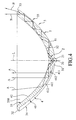
- the preferred embodiment of a light guide lens according to this invention is shown to be adapted for guiding light emitted from a light emitting element 20.
- the light emitting element 20 is exemplified by a light emitting diode (LED).
- the light guide lens is made of a resin material, is substantially bowl-shaped, and includes a base portion 2 and a light guide portion 3.
- the base portion 2 is disposed on a light axis (L) and the light axis (L) passes the central position of the base portion 2.
- the base portion 2 includes a light incident surface 21 adapted for passing of the light emitted from the light emitting element 20 therethrough.
- the light incident surface 21 surrounds the light axis (L) and diverges toward the light emitting element 20 so as to form a cone surface.
- the light guide portion 3 surrounds the light axis (L) and extends and diverges from the periphery of the base portion 2 in a direction away from the base portion 2.
- the light guide portion 3 includes an inner peripheral edge 31 connected to the base portion 2 and surrounding the light axis (L), an outer peripheral edge 32 opposite to the inner peripheral edge 31, disposed distally from the base portion 2 and surrounding the light axis (L), and at least one light control unit 33 connecting the inner peripheral edge 31 and the outer peripheral edge 32.
- the light guide portion 3 of this embodiment includes a plurality of light control units 33 that are connected to one another to form a ring that surrounds the light axis (L).
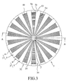
- Each of the light control units 33 has a first light guide section 4 and a second light guide section 5 that are adjacent to each other and that extend from the inner peripheral edge 31 toward the outer peripheral edge 32.
- the first light guide section 4 of each of the light control units 33 is connected to the second light guide section 5 of an adjacent one of the light control units 33.
- the first light guide sections 4 and the second light guide sections 5 are interleaved with each other.
- the first light guide sections 4 includes a first reflecting surface 41 facing the light emitting element 20 and a first light exiting surface 42 facing away from the light emitting element 20 and having a curvature.
- the first reflecting surface 41 has a stepped shape, and includes a plurality of first areas 411 and a plurality of second areas 412 interleaved with each other.
- the first reflecting surface 41 has a textured structure; whereas the first light exiting surface 42 has a smooth face.
- the second light guide section 5 of this embodiment includes a second reflecting surface 51 facing the light emitting element 20, a third reflecting surface 52 facing away from the light emitting element 20, a second light exiting surface 53 connecting an edge of the second reflecting surface 51 and an edge of the third reflecting surface 52, and disposed on the outer peripheral edge 32, and a pair of lateral sides 54 that are spaced apart from each other with the second reflecting surface 51 interposed therebetween.
- Each of the lateral sides 54 connects the second reflecting surface 51 and the first reflecting surface 41 of an adjacent first light guide section 4.
- the second reflecting surface 51 and the third reflecting surface 52 has a smooth face and extends from the inner peripheral edge 31 toward the outer peripheral edge 32.
- the lateral sides 54 also extend from the inner peripheral edge 31 toward the outer peripheral edge 32, and the distance therebetween gets larger from the inner peripheral edge 31 toward the outer peripheral edge 32.
- the light guide portion 3 further includes a first surface 34 facing the light emitting element 20 and a second surface 35 facing away from the light emitting element 20 and defining a lens space 350.
- the first surface 34 is defined by the first reflecting surfaces 41 in cooperation with the second reflecting surfaces 51 of the light control units 33
- the second surface 35 is defined by the first light exiting surfaces 42 in cooperation with the third reflecting surfaces 52 of the light control units 33.
- the light emitting element 20 is adapted to be disposed to face the light incident surface 21 of the light guide lens so that light emitted from the light emitting element 20 enters the light guide lens through the light incident surface 21.
- the light is reflected (mainly by total reflections) again by the first reflecting surfaces 41 as to be emitted out of the first light exiting surfaces 42, as shown by the traveling optical paths (A) in Figure 4 .
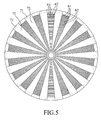
- light entering the first light exiting surfaces 42 forms a light pattern composed of a plurality of first bright stripes 61 (as best shown in dotted areas in Figure 5 ) and a plurality of first dim stripes 62 interleaved with each other.
- the light intensity of the first dim stripes 62 is very small or almost null, and the light intensity of the first dim stripes 62 is smaller than that of the first bright stripes 61.
- the light distribution guided by the second light guide sections 5 includes a plurality of second bright areas 71 at locations corresponding to the second light exiting surfaces 53, and a plurality of second dim areas 72 at locations of the second light guide sections 5 outside the second bright areas 71.
- the intensity of the light of the second dim areas 72 is very small or almost null, and the intensity of the light of the second dim areas 72 is smaller than that of the light of the second bright areas 71.
- the first light guide sections 4 and the second light guide sections 5 are able to guide the light emitted from the light emitting element 20 exemplified by a point light source in the preferred embodiment, to form a special light pattern.
- the first bright stripes 61 are interleaved with the first dim stripes 62.
- a triangular second dim area 72 is disposed, and the second bright area 71 is disposed on the raidal outer edge of the second dim area 72.
- the first light guide sections 4 are used to make light undergo two reflections before coming out of the light guide lens
- the second light guide sections 5 are used to make light undergo multiple reflections before exiting the outer peripheral edge 32. So by such an innovative structure, this invention generates an optical functionality and an optical projection pattern which are quite distinct from those generated by the light guide lenses in the prior art.
- the light guide lens of this invention with the cooperation of the light emitting element 20 is well suited for use in vehicular lamps, other lighting apparatus, signal lights, decorative lightings or advertising light boxes, etc.
Landscapes
- Engineering & Computer Science (AREA)
- General Engineering & Computer Science (AREA)
- Physics & Mathematics (AREA)
- Optics & Photonics (AREA)
- General Physics & Mathematics (AREA)
- Microelectronics & Electronic Packaging (AREA)
- Non-Portable Lighting Devices Or Systems Thereof (AREA)
- Optical Couplings Of Light Guides (AREA)
Applications Claiming Priority (1)
| Application Number | Priority Date | Filing Date | Title |
|---|---|---|---|
| TW102120113A TW201447178A (zh) | 2013-06-06 | 2013-06-06 | 導光透鏡 |
Publications (2)
| Publication Number | Publication Date |
|---|---|
| EP2811218A2 true EP2811218A2 (de) | 2014-12-10 |
| EP2811218A3 EP2811218A3 (de) | 2015-09-09 |
Family
ID=50439112
Family Applications (1)
| Application Number | Title | Priority Date | Filing Date |
|---|---|---|---|
| EP14001192.5A Withdrawn EP2811218A3 (de) | 2013-06-06 | 2014-03-31 | Lichtführungslinse |
Country Status (3)
| Country | Link |
|---|---|
| US (1) | US9146019B2 (de) |
| EP (1) | EP2811218A3 (de) |
| TW (1) | TW201447178A (de) |
Cited By (4)
| Publication number | Priority date | Publication date | Assignee | Title |
|---|---|---|---|---|
| CN104089233A (zh) * | 2014-07-17 | 2014-10-08 | 常州九鼎车业有限公司 | 光导式汽车侧转向灯 |
| CN106641950A (zh) * | 2015-11-04 | 2017-05-10 | 现代自动车欧洲技术研究中心有限公司 | 用于车灯的光引导模块以及制造该光引导模块的方法 |
| EP3473920A1 (de) * | 2017-10-20 | 2019-04-24 | Stanley Electric Co., Ltd. | Fahrzeugbeleuchtungsvorrichtung und linsenkörper |
| EP3499114A1 (de) * | 2017-12-14 | 2019-06-19 | T.Y.C. Brother Industrial Co., Ltd. | Fahrzeuglampenlinse |
Families Citing this family (8)
| Publication number | Priority date | Publication date | Assignee | Title |
|---|---|---|---|---|
| TWI507640B (zh) * | 2013-07-22 | 2015-11-11 | Radiant Opto Electronics Corp | 可控制光束角之導光元件及燈具 |
| JP2015215946A (ja) * | 2014-05-07 | 2015-12-03 | 市光工業株式会社 | 車両用灯具 |
| US10161591B2 (en) * | 2015-08-31 | 2018-12-25 | Osram Sylvania Inc. | Thin wall internal reflection light optic |
| DE102017111912A1 (de) * | 2017-05-31 | 2018-12-06 | Itz Innovations- Und Technologiezentrum Gmbh | Modularer Lichtleiter |
| JP2019125532A (ja) * | 2018-01-18 | 2019-07-25 | 株式会社小糸製作所 | 灯具 |
| CN111367118B (zh) * | 2018-12-25 | 2023-04-28 | 中强光电股份有限公司 | 光源模块与分光元件 |
| CN112032672B (zh) * | 2019-06-03 | 2025-01-10 | 扬州雷笛克光学有限公司 | 混光透镜 |
| JP2025115875A (ja) * | 2024-01-26 | 2025-08-07 | 株式会社東海理化電機製作所 | 発光エンブレム |
Citations (1)
| Publication number | Priority date | Publication date | Assignee | Title |
|---|---|---|---|---|
| US7270454B2 (en) | 2004-01-13 | 2007-09-18 | Koito Manufacturing Co., Ltd. | Vehicular lamp |
Family Cites Families (12)
| Publication number | Priority date | Publication date | Assignee | Title |
|---|---|---|---|---|
| JP3195294B2 (ja) * | 1998-08-27 | 2001-08-06 | スタンレー電気株式会社 | 車両用灯具 |
| JP4153370B2 (ja) * | 2002-07-04 | 2008-09-24 | 株式会社小糸製作所 | 車両用灯具 |
| FR2846400B1 (fr) * | 2002-10-28 | 2005-10-07 | Valeo Vision | Feu de signalisation comportant un dispositif de recuperation et de repartition du flux lumineux vers un reflecteur annulaire |
| ITTO20030801A1 (it) * | 2003-10-14 | 2005-04-15 | Fiat Ricerche | Perfezionamenti negli apparecchi di illuminazione. |
| JP2005158362A (ja) * | 2003-11-21 | 2005-06-16 | Stanley Electric Co Ltd | 車両用灯具 |
| JP4113111B2 (ja) * | 2003-12-24 | 2008-07-09 | 株式会社小糸製作所 | 車両用灯具ユニットおよび車両用照明灯具 |
| ATE453930T1 (de) * | 2004-10-14 | 2010-01-15 | Fiat Ricerche | Optikelement und modul zur projektion eines lichtbündels, und kraftfahrzeugleuchte mit einer mehrzahl solcher modulen |
| JP5374140B2 (ja) * | 2008-12-22 | 2013-12-25 | 株式会社小糸製作所 | 車輌用灯具 |
| JP5442321B2 (ja) * | 2009-01-27 | 2014-03-12 | 株式会社小糸製作所 | 車両用灯具 |
| JP5472594B2 (ja) * | 2009-08-18 | 2014-04-16 | スタンレー電気株式会社 | 車両用灯具 |
| DE102011051978A1 (de) * | 2011-07-20 | 2013-01-24 | Tap Ltd. | Rücklicht |
| TWM451275U (zh) * | 2012-11-12 | 2013-04-21 | Tyc Brother Ind Co Ltd | 可產生均勻亮度的車燈透鏡 |
-
2013
- 2013-06-06 TW TW102120113A patent/TW201447178A/zh unknown
-
2014
- 2014-03-31 EP EP14001192.5A patent/EP2811218A3/de not_active Withdrawn
- 2014-04-07 US US14/246,334 patent/US9146019B2/en active Active
Patent Citations (1)
| Publication number | Priority date | Publication date | Assignee | Title |
|---|---|---|---|---|
| US7270454B2 (en) | 2004-01-13 | 2007-09-18 | Koito Manufacturing Co., Ltd. | Vehicular lamp |
Cited By (4)
| Publication number | Priority date | Publication date | Assignee | Title |
|---|---|---|---|---|
| CN104089233A (zh) * | 2014-07-17 | 2014-10-08 | 常州九鼎车业有限公司 | 光导式汽车侧转向灯 |
| CN106641950A (zh) * | 2015-11-04 | 2017-05-10 | 现代自动车欧洲技术研究中心有限公司 | 用于车灯的光引导模块以及制造该光引导模块的方法 |
| EP3473920A1 (de) * | 2017-10-20 | 2019-04-24 | Stanley Electric Co., Ltd. | Fahrzeugbeleuchtungsvorrichtung und linsenkörper |
| EP3499114A1 (de) * | 2017-12-14 | 2019-06-19 | T.Y.C. Brother Industrial Co., Ltd. | Fahrzeuglampenlinse |
Also Published As
| Publication number | Publication date |
|---|---|
| EP2811218A3 (de) | 2015-09-09 |
| US20140362588A1 (en) | 2014-12-11 |
| TWI489061B (de) | 2015-06-21 |
| US9146019B2 (en) | 2015-09-29 |
| TW201447178A (zh) | 2014-12-16 |
Similar Documents
| Publication | Publication Date | Title |
|---|---|---|
| EP2811218A2 (de) | Lichtführungslinse | |
| US11460623B2 (en) | LED lighting lamp | |
| US8911118B2 (en) | Lens, LED module and illumination system having same | |
| US10060592B2 (en) | Dual beam pattern vehicular lighting assembly | |
| US9360169B2 (en) | Lens, LED module and illumination system with asymmetric lighting distribution | |
| EP2886937A1 (de) | Lichtleitervorrichtung | |
| JP2010251013A (ja) | 灯具 | |
| KR102077075B1 (ko) | 원형 라이트 가이드 및 이를 포함하는 차량용 램프 | |
| JP6091789B2 (ja) | 光束制御部材、発光装置および照明装置 | |
| WO2018158110A1 (en) | Luminaire with light guide | |
| US9151461B1 (en) | Lens for a vehicular lamp | |
| CN103836541B (zh) | 一种导光件及平行光源照明装置 | |
| US20140043840A1 (en) | Light module | |
| CN201141550Y (zh) | 光分布光栅板 | |
| CN104296067B (zh) | 导光透镜 | |
| US8911132B1 (en) | Edgelit optic entrance features | |
| TW201409096A (zh) | 模組化微結構導光裝置 | |
| CN104791714A (zh) | 集光导光器 | |
| KR102145189B1 (ko) | 차량용 램프 | |
| JP2012209049A (ja) | Led照明装置およびレンズ | |
| CN104797880B (zh) | 具有三维效果的车辆信号装置 | |
| KR20180111025A (ko) | 차량용 램프 | |
| KR20170045805A (ko) | 차량용 램프 | |
| US8764258B2 (en) | Inner lens for vehicle light and vehicle light including the same | |
| TWM451275U (zh) | 可產生均勻亮度的車燈透鏡 |
Legal Events
| Date | Code | Title | Description |
|---|---|---|---|
| PUAI | Public reference made under article 153(3) epc to a published international application that has entered the european phase |
Free format text: ORIGINAL CODE: 0009012 |
|
| 17P | Request for examination filed |
Effective date: 20140331 |
|
| AK | Designated contracting states |
Kind code of ref document: A2 Designated state(s): AL AT BE BG CH CY CZ DE DK EE ES FI FR GB GR HR HU IE IS IT LI LT LU LV MC MK MT NL NO PL PT RO RS SE SI SK SM TR |
|
| AX | Request for extension of the european patent |
Extension state: BA ME |
|
| R17P | Request for examination filed (corrected) |
Effective date: 20141118 |
|
| RBV | Designated contracting states (corrected) |
Designated state(s): AL AT BE BG CH CY CZ DE DK EE ES FI FR GB GR HR HU IE IS IT LI LT LU LV MC MK MT NL NO PL PT RO RS SE SI SK SM TR |
|
| PUAL | Search report despatched |
Free format text: ORIGINAL CODE: 0009013 |
|
| AK | Designated contracting states |
Kind code of ref document: A3 Designated state(s): AL AT BE BG CH CY CZ DE DK EE ES FI FR GB GR HR HU IE IS IT LI LT LU LV MC MK MT NL NO PL PT RO RS SE SI SK SM TR |
|
| AX | Request for extension of the european patent |
Extension state: BA ME |
|
| RIC1 | Information provided on ipc code assigned before grant |
Ipc: F21S 8/10 20060101AFI20150731BHEP |
|
| STAA | Information on the status of an ep patent application or granted ep patent |
Free format text: STATUS: THE APPLICATION HAS BEEN WITHDRAWN |
|
| 18W | Application withdrawn |
Effective date: 20190122 |