EP2811232A1 - Élément de plafond pour un plafond chauffant et rafraîchissant ainsi que plafond chauffant et rafraîchissant - Google Patents
Élément de plafond pour un plafond chauffant et rafraîchissant ainsi que plafond chauffant et rafraîchissant Download PDFInfo
- Publication number
- EP2811232A1 EP2811232A1 EP13405131.7A EP13405131A EP2811232A1 EP 2811232 A1 EP2811232 A1 EP 2811232A1 EP 13405131 A EP13405131 A EP 13405131A EP 2811232 A1 EP2811232 A1 EP 2811232A1
- Authority
- EP
- European Patent Office
- Prior art keywords
- ceiling
- cooling
- air
- ceiling element
- ribs
- Prior art date
- Legal status (The legal status is an assumption and is not a legal conclusion. Google has not performed a legal analysis and makes no representation as to the accuracy of the status listed.)
- Withdrawn
Links
- 238000001816 cooling Methods 0.000 title claims abstract description 64
- 238000010438 heat treatment Methods 0.000 title claims description 25
- 239000012530 fluid Substances 0.000 claims abstract description 22
- 239000007788 liquid Substances 0.000 claims description 20
- 239000011810 insulating material Substances 0.000 claims description 2
- 230000005855 radiation Effects 0.000 abstract description 5
- 230000000694 effects Effects 0.000 abstract description 4
- 239000003570 air Substances 0.000 description 41
- 239000000110 cooling liquid Substances 0.000 description 4
- 239000012809 cooling fluid Substances 0.000 description 2
- 238000005338 heat storage Methods 0.000 description 2
- 238000009413 insulation Methods 0.000 description 2
- 229910052751 metal Inorganic materials 0.000 description 2
- 239000002184 metal Substances 0.000 description 2
- RYGMFSIKBFXOCR-UHFFFAOYSA-N Copper Chemical compound [Cu] RYGMFSIKBFXOCR-UHFFFAOYSA-N 0.000 description 1
- 206010067623 Radiation interaction Diseases 0.000 description 1
- 239000000853 adhesive Substances 0.000 description 1
- 230000001070 adhesive effect Effects 0.000 description 1
- 229910052782 aluminium Inorganic materials 0.000 description 1
- XAGFODPZIPBFFR-UHFFFAOYSA-N aluminium Chemical compound [Al] XAGFODPZIPBFFR-UHFFFAOYSA-N 0.000 description 1
- 239000012080 ambient air Substances 0.000 description 1
- 230000003321 amplification Effects 0.000 description 1
- 239000012267 brine Substances 0.000 description 1
- 238000010276 construction Methods 0.000 description 1
- 239000002826 coolant Substances 0.000 description 1
- 229910052802 copper Inorganic materials 0.000 description 1
- 239000010949 copper Substances 0.000 description 1
- 238000013016 damping Methods 0.000 description 1
- 238000005265 energy consumption Methods 0.000 description 1
- 239000006260 foam Substances 0.000 description 1
- 239000011490 mineral wool Substances 0.000 description 1
- 238000003199 nucleic acid amplification method Methods 0.000 description 1
- HPALAKNZSZLMCH-UHFFFAOYSA-M sodium;chloride;hydrate Chemical compound O.[Na+].[Cl-] HPALAKNZSZLMCH-UHFFFAOYSA-M 0.000 description 1
- XLYOFNOQVPJJNP-UHFFFAOYSA-N water Substances O XLYOFNOQVPJJNP-UHFFFAOYSA-N 0.000 description 1
Images



Classifications
-
- F—MECHANICAL ENGINEERING; LIGHTING; HEATING; WEAPONS; BLASTING
- F24—HEATING; RANGES; VENTILATING
- F24D—DOMESTIC- OR SPACE-HEATING SYSTEMS, e.g. CENTRAL HEATING SYSTEMS; DOMESTIC HOT-WATER SUPPLY SYSTEMS; ELEMENTS OR COMPONENTS THEREFOR
- F24D3/00—Hot-water central heating systems
- F24D3/12—Tube and panel arrangements for ceiling, wall, or underfloor heating
- F24D3/16—Tube and panel arrangements for ceiling, wall, or underfloor heating mounted on, or adjacent to, a ceiling, wall or floor
-
- F—MECHANICAL ENGINEERING; LIGHTING; HEATING; WEAPONS; BLASTING
- F24—HEATING; RANGES; VENTILATING
- F24F—AIR-CONDITIONING; AIR-HUMIDIFICATION; VENTILATION; USE OF AIR CURRENTS FOR SCREENING
- F24F13/00—Details common to, or for air-conditioning, air-humidification, ventilation or use of air currents for screening
- F24F13/02—Ducting arrangements
- F24F13/06—Outlets for directing or distributing air into rooms or spaces, e.g. ceiling air diffuser
- F24F13/072—Outlets for directing or distributing air into rooms or spaces, e.g. ceiling air diffuser of elongated shape, e.g. between ceiling panels
-
- F—MECHANICAL ENGINEERING; LIGHTING; HEATING; WEAPONS; BLASTING
- F24—HEATING; RANGES; VENTILATING
- F24F—AIR-CONDITIONING; AIR-HUMIDIFICATION; VENTILATION; USE OF AIR CURRENTS FOR SCREENING
- F24F5/00—Air-conditioning systems or apparatus not covered by F24F1/00 or F24F3/00, e.g. using solar heat or combined with household units such as an oven or water heater
- F24F5/0089—Systems using radiation from walls or panels
- F24F5/0092—Systems using radiation from walls or panels ceilings, e.g. cool ceilings
-
- F—MECHANICAL ENGINEERING; LIGHTING; HEATING; WEAPONS; BLASTING
- F24—HEATING; RANGES; VENTILATING
- F24F—AIR-CONDITIONING; AIR-HUMIDIFICATION; VENTILATION; USE OF AIR CURRENTS FOR SCREENING
- F24F7/00—Ventilation
- F24F7/04—Ventilation with ducting systems, e.g. by double walls; with natural circulation
- F24F7/06—Ventilation with ducting systems, e.g. by double walls; with natural circulation with forced air circulation, e.g. by fan positioning of a ventilator in or against a conduit
- F24F7/10—Ventilation with ducting systems, e.g. by double walls; with natural circulation with forced air circulation, e.g. by fan positioning of a ventilator in or against a conduit with air supply, or exhaust, through perforated wall, floor or ceiling
-
- Y—GENERAL TAGGING OF NEW TECHNOLOGICAL DEVELOPMENTS; GENERAL TAGGING OF CROSS-SECTIONAL TECHNOLOGIES SPANNING OVER SEVERAL SECTIONS OF THE IPC; TECHNICAL SUBJECTS COVERED BY FORMER USPC CROSS-REFERENCE ART COLLECTIONS [XRACs] AND DIGESTS
- Y02—TECHNOLOGIES OR APPLICATIONS FOR MITIGATION OR ADAPTATION AGAINST CLIMATE CHANGE
- Y02B—CLIMATE CHANGE MITIGATION TECHNOLOGIES RELATED TO BUILDINGS, e.g. HOUSING, HOUSE APPLIANCES OR RELATED END-USER APPLICATIONS
- Y02B30/00—Energy efficient heating, ventilation or air conditioning [HVAC]
Definitions
- the invention relates to a ceiling element for a heating and cooling ceiling and a heating and cooling ceiling, which comprises at least one such ceiling element.
- the invention is based on the object of specifying a ceiling element, in which cooling air is supplied so that form no disturbing compact cold air flows, but nevertheless offers a high cooling capacity. Moreover should be given a heating and cooling ceiling, which also has these properties.
- the inventive ceiling element allows the construction of cooling ceilings, in which the supplied cooling air does not flow directly down into the space to be cooled, but drives an air roll in which it quickly mixed with a multiple of room air, so that the supplied cooling air does not form compact cold air flows can. In this way, a high cooling performance can be achieved without unpleasant drafts occur.
- the inventive ceiling element When forming the inventive ceiling element with an upper liquid circle, it is also possible to include the ceiling, usually a concrete ceiling, more in the cooling by being used as a heat storage.
- the ceiling element according to the invention can be further developed in such a way that it also includes a liquid circuit for the direct space cooling, which serves for additional radiation cooling of the room and can also be used to enhance the use of the ceiling for cooling.
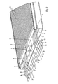
- the inventive heating and cooling ceiling consists in the example ( Fig. 1 ) of two consecutively, ie arranged in a row according to the invention ceiling elements 1, 1 ', which are formed substantially the same. It is suitable for cooling and, if necessary, also for heating a smaller room.
- the heating and cooling ceiling preferably comprises a number of ceiling elements, which may be longer than shown, but it may also comprise a plurality of preferably parallel rows, which should then be laterally spaced from each other clearly, so that the air flow is not hindered.
- the cover element 1 is in each case of rectangular base area and has an elongate air box 2 continuous in a longitudinal direction, which in the example consists of a downwardly open U-profile 3 and a floor 4.
- the volume of air enclosed by the air box 2 thus has the shape of an air channel 5 (FIG. Fig. 2 ).
- the air box 2 of the ceiling element 1 adjoins a distribution box (not shown) guided past a left end thereof. At its outer end, the air box 2 of the further ceiling element 1 'connects directly. This is closed at its outer end.
- the upper part of the U-profile 3 forms a horizontal ceiling 6 of the air channel 5, are attached to the longitudinally consecutive punched outflow openings 7, which all on the same side (in Fig. 1 and 2 obliquely forward) are open and directed.
- the remaining space is each closed by a lid 8, which comprises a flat part which lies in the same plane as the ceiling 6, and forms a groove 9 at the edge of the ceiling element.
- a lid 8 which comprises a flat part which lies in the same plane as the ceiling 6, and forms a groove 9 at the edge of the ceiling element.
- Over the top of the ceiling 6 and the lid 8 run in the transverse direction substantially continuous ribs 10, which follow one another in the longitudinal direction regularly and at a small distance, such that between two successive ribs 10 each one of the outflow 7 is located.
- a continuous plate 11 made of metal, preferably aluminum, which is followed by an insulating layer, which is formed as a mat or preferably as an insulating plate 12 of a thermally insulating material, for example made of rock wool or a preferably open-cell foam, and which simultaneously the noise damping is used.
- the ceiling element 1 is made of a continuous perforated plate 13 (the perforation is in Fig. 1 and 8th each shown only on a part of the surface) completed, which is suspended by lateral mounting flanges on vertical edge strips of the lid 8.
- the ceiling element 1 also has an upper fluid circuit 14 which is composed of tubes, preferably copper tubes, and hoses and forms a loop with a first longitudinally extending straight tube 15, which in one of the grooves 9th is guided by aligned openings in the ribs 10 and a second straight pipe 16 which is guided in the other groove 9 at the opposite edge of the ceiling member in the same way, such that the upper liquid circuit 14 through openings at the opposite ends of each of the ribs 10th running.
- the two straight tubes 15, 16 are connected by a transverse also substantially straight connection tube 17 at the outer end of the ceiling element 1. They are in each case in contact with the edges of the openings in the ribs 10, preferably pressed into them, such that they are in close heat-conducting connection with them.
- the upper fluid circuit 14 connects an upper supply port on a ceiling duct 18 to an upper discharge port on a return 19.
- a lower fluid circuit 20 comprises a meandering tube, which is arranged between the insulation plate 12 and the perforated plate 13 and is in close heat-conducting connection with the latter. It can only be placed on the perforated plate 13 or glued to it or connected in some other way.
- the lower fluid circuit 20 connects a lower supply port to a room flow 21 with a lower discharge port on the return 19.
- the further ceiling element 1 ' has a very similar upper fluid circuit 14', which includes only additional connecting hoses, which run in the longitudinal direction through the first ceiling element 1 , as well as a lower fluid circuit 20 ', which also includes longer connecting hoses.
- the ceiling flow 18, the return 19 and the room flow 21 run, parallel to the distribution box for the cooling air, not shown, in the transverse direction and usually serve to supply several rows of ceiling elements, which also belong to different heating and cooling ceilings, that can be arranged in different rooms, with heat transfer medium, usually water or brine supply. They can each be closed at a remote end.
- the ceiling elements 1, 1 'of a row can be connected in parallel with the ceiling duct 18, the return 19 and the room flow 21, which leads to a particularly uniform cooling or heating effect, but a connection in series is also possible.
- the ceiling elements 1, 1 ' are just below a ceiling - usually a concrete ceiling attached, preferably directly on the underside, such that the upper ends of the ribs 10 touch the ceiling or else are in close heat-conducting contact with her.
- a cover plate made of metal can also be provided, which rests on the ribs and connected to them and also thermally coupled to the ceiling, e.g. is glued to it by means of a good heat-conducting adhesive.
- the ceiling 6 of the air box is preferably about 2cm to 5cm below the ceiling or possibly the cover plate. The spaces between two adjacent ribs 10 thus each form a channel in which one of the outflow openings 7 is located.
- cooling air from the distribution channel in the air duct 5 flows out of the discharge openings 7 on the ceiling 6 of the air box 2 and into these channels, where it generates a flow of air in the transverse direction, which in all channels the same direction to one edge of the Ceiling element 1, 1 'has (in Fig.1 and 2 diagonally forward right).
- room air is drawn into the channels at the opposite edge and an air roll in the space to be cooled produced and maintained, which forms a light, consisting of the supplied cold air and the about 20- to 30-fold of mitbewegter ambient air flow that cools the room with high cooling capacity, but without disturbing compact cold air flows.
- the cooling effect can be enhanced by passing cooling liquid through the upper liquid circuits 14, 14 '. Characterized the lid 8 and especially the ribs 10 are cooled, so that the air flowing through the laterally limited by the ribs 10 channels is additionally cooled by the contact with the ribs 10 and the covers 8.
- cooling effect can be achieved by passing cooling fluid through the lower fluid circuits 20, 20 '.
- each of the perforated plate 13 is cooled, which causes additional cooling of the underlying space by radiation exchange.
- the upper and lower fluid circuits also offer the possibility of utilizing the thermal inertia of the ceiling (concrete core cooling).
- the possible operations with regard to the use of the upper fluid circuits 14, 14 'and the lower fluid circuits 20, 20' are in Fig. 9-11 shown schematically.
- a valve 22 is shown in the return 19, with which it can be locked and a connecting line 23 between the room flow 21 and the ceiling lead 18 with a pump 24th
- valve 22 is open. Coolant is directed into the ceiling lead 18 and flows through the upper fluid circuits 14, 14 'to the return 19. This can be done as described above during periods of high heat load in addition to the air cooling, which is thereby amplified. But it is also possible, during times of low heat load, especially at night, with or without additional cooling air supply, to guide cooling liquid through the upper fluid circuits 14, 14 'and to cool the latter via the heat-conductive connection of the ribs 10 with the ceiling.
- the cold room ceiling can be used in addition to the radiation cooling of the room.
- the valve 22 is closed and the pump 24 in operation.
- cooling liquid is passed through the upper liquid circuits 14, 14 ', where it cools by heat exchange with the ceiling via the ribs 10 and further through the lower liquid circuits 20, 20', where it cools the orifice plate 13, which then via radiation interaction cool the room.
- the direction of flow can also be reversed.
- cooling fluid can flow through the ceiling flow at the same time 18 and the space lead 21 and fed in parallel through the upper fluid circuits 14, 14 'and the lower fluid circuits 20, 20' are led to the return 19, so that at the same time an amplification of the air cooling through the upper fluid circuits 14, 14 'and an additional radiation cooling through the lower liquid circuits 20, 20 'takes place.
- Cooling ceiling shown in its basic structure can be used advantageously regardless of the details of the ceiling elements, if they have a space cooling circuit, for example, also in the case that an upper liquid circle is embedded directly in the ceiling.
- ceiling elements are used primarily for cooling, use for heating purposes is just as possible. The same modes of operation can be used and the ceiling can be used as a heat storage.
- the inventive ceiling element and the inventive heating and cooling ceiling offer a relatively simple structure a variety of applications. They can be used for air cooling as well as radiant cooling. Air cooling can be enhanced by liquid cooling. It is possible to use concrete core cooling and to use it for air cooling as well as for radiant cooling. The mode of operation can thus be adapted extremely flexibly to the given conditions and adjusted with regard to various parameters such as cooling capacity, air supply and energy consumption.
Landscapes
- Engineering & Computer Science (AREA)
- Chemical & Material Sciences (AREA)
- Combustion & Propulsion (AREA)
- Mechanical Engineering (AREA)
- General Engineering & Computer Science (AREA)
- Life Sciences & Earth Sciences (AREA)
- Sustainable Development (AREA)
- Physics & Mathematics (AREA)
- Thermal Sciences (AREA)
- Devices For Blowing Cold Air, Devices For Blowing Warm Air, And Means For Preventing Water Condensation In Air Conditioning Units (AREA)
Applications Claiming Priority (1)
| Application Number | Priority Date | Filing Date | Title |
|---|---|---|---|
| CH02619/12A CH707246A1 (de) | 2012-11-29 | 2012-11-29 | Deckenelement für eine Heiz- und Kühldecke sowie Heiz- und Kühldecke. |
Publications (1)
| Publication Number | Publication Date |
|---|---|
| EP2811232A1 true EP2811232A1 (fr) | 2014-12-10 |
Family
ID=47632638
Family Applications (1)
| Application Number | Title | Priority Date | Filing Date |
|---|---|---|---|
| EP13405131.7A Withdrawn EP2811232A1 (fr) | 2012-11-29 | 2013-11-26 | Élément de plafond pour un plafond chauffant et rafraîchissant ainsi que plafond chauffant et rafraîchissant |
Country Status (2)
| Country | Link |
|---|---|
| EP (1) | EP2811232A1 (fr) |
| CH (1) | CH707246A1 (fr) |
Cited By (1)
| Publication number | Priority date | Publication date | Assignee | Title |
|---|---|---|---|---|
| EP3309314A1 (fr) | 2016-10-17 | 2018-04-18 | Barcol-Air Group AG | Élement de plafond et plafond chauffant et refroidissant |
Families Citing this family (1)
| Publication number | Priority date | Publication date | Assignee | Title |
|---|---|---|---|---|
| DE202017103113U1 (de) * | 2017-05-23 | 2017-07-31 | Erwin Müller GmbH | Decken-Klimatisierungsvorrichtung mit Tragkonstruktion |
Citations (6)
| Publication number | Priority date | Publication date | Assignee | Title |
|---|---|---|---|---|
| WO1993015366A1 (fr) * | 1992-02-03 | 1993-08-05 | Ke-Burgman A/S | Procede et tube d'injection d'air |
| WO2005023395A1 (fr) | 2003-09-05 | 2005-03-17 | Zuk Peter Jr | Appareil de filtration de liquide biologique |
| DE202004020334U1 (de) * | 2004-04-13 | 2005-03-31 | Thermosoft Klimatechnik Gmbh | Decke, insbesondere Kühl- oder Heizdecke |
| CH695835A5 (de) | 2002-04-03 | 2006-09-15 | Trox Hesco Schweiz Ag | Anordnung zum Kühlen von Räumen. |
| DE102008039371A1 (de) * | 2008-08-22 | 2010-02-25 | Bolz Intec Gmbh | Verfahren und Vorrichtung zur Verbesserung des Wirkungsgrades beim Beheizen eines Raumes mittels eines Gasstrahles aus einem erwärmten gasförmigen Medium |
| DE102011111434A1 (de) * | 2011-08-25 | 2013-02-28 | Lindner Ag | Verfahren und Vorrichtung zum Klimatisieren eines Raumes |
Family Cites Families (5)
| Publication number | Priority date | Publication date | Assignee | Title |
|---|---|---|---|---|
| SE459447B (sv) * | 1987-06-17 | 1989-07-03 | Stefan Jacek Moszkowski | Saett och anordning foer att ventilera ett rum genom inblaasning av luft horisontellt under en vaermevaexlande takmonterad panel |
| NL1004187C2 (nl) * | 1996-10-03 | 1998-04-06 | Luchttechnisch Adviesbureau Ev | Convector. |
| DE102004018278B4 (de) * | 2004-04-13 | 2006-01-19 | Thermosoft Klimatechnik Gmbh | Decke, insbesondere Kühl-oder Heizdecke |
| DE102008054181A1 (de) * | 2008-10-31 | 2010-05-12 | Frenger Systemen BV Heiz- und Kühltechnik GmbH | Klimaeinrichtung |
| KR101224372B1 (ko) * | 2009-04-13 | 2013-01-21 | 키무라코우키 가부시키가이샤 | 냉난방유닛 및 냉난방장치 |
-
2012
- 2012-11-29 CH CH02619/12A patent/CH707246A1/de not_active Application Discontinuation
-
2013
- 2013-11-26 EP EP13405131.7A patent/EP2811232A1/fr not_active Withdrawn
Patent Citations (6)
| Publication number | Priority date | Publication date | Assignee | Title |
|---|---|---|---|---|
| WO1993015366A1 (fr) * | 1992-02-03 | 1993-08-05 | Ke-Burgman A/S | Procede et tube d'injection d'air |
| CH695835A5 (de) | 2002-04-03 | 2006-09-15 | Trox Hesco Schweiz Ag | Anordnung zum Kühlen von Räumen. |
| WO2005023395A1 (fr) | 2003-09-05 | 2005-03-17 | Zuk Peter Jr | Appareil de filtration de liquide biologique |
| DE202004020334U1 (de) * | 2004-04-13 | 2005-03-31 | Thermosoft Klimatechnik Gmbh | Decke, insbesondere Kühl- oder Heizdecke |
| DE102008039371A1 (de) * | 2008-08-22 | 2010-02-25 | Bolz Intec Gmbh | Verfahren und Vorrichtung zur Verbesserung des Wirkungsgrades beim Beheizen eines Raumes mittels eines Gasstrahles aus einem erwärmten gasförmigen Medium |
| DE102011111434A1 (de) * | 2011-08-25 | 2013-02-28 | Lindner Ag | Verfahren und Vorrichtung zum Klimatisieren eines Raumes |
Non-Patent Citations (1)
| Title |
|---|
| FRITZ NÜSSLE ET AL: "Kühldeckensystem mit Aktivierung der Speichermasse der Betondecke", BAUPHYSIK, vol. 33, no. 1, 10 February 2011 (2011-02-10), pages 43 - 48, XP055111757, ISSN: 0171-5445, DOI: 10.1002/bapi.201110005 * |
Cited By (1)
| Publication number | Priority date | Publication date | Assignee | Title |
|---|---|---|---|---|
| EP3309314A1 (fr) | 2016-10-17 | 2018-04-18 | Barcol-Air Group AG | Élement de plafond et plafond chauffant et refroidissant |
Also Published As
| Publication number | Publication date |
|---|---|
| CH707246A1 (de) | 2014-05-30 |
Similar Documents
| Publication | Publication Date | Title |
|---|---|---|
| EP2476970B1 (fr) | Réservoir de fluide | |
| EP1959207A1 (fr) | Couverture climatisée et son procédé de fonctionnement | |
| EP3499145A1 (fr) | Dispositif de mise en température d'un espace | |
| DE102008006513A1 (de) | Wärmetauscher | |
| EP1078205B1 (fr) | Element de refroidissement a air, procede permettant de le faire fonctionner, et dispositif de refroidissement a air | |
| EP1586823B1 (fr) | Plafond, en particulier plafond réfrigérant ou chauffant | |
| EP1541934B1 (fr) | Elément de refroidissement, dispositif de refroidissement et son procédé d'operation | |
| EP2811232A1 (fr) | Élément de plafond pour un plafond chauffant et rafraîchissant ainsi que plafond chauffant et rafraîchissant | |
| DE69823405T2 (de) | Deckenelement | |
| CH707080B1 (de) | Baugruppe zum Kühlen oder Heizen sowie Kühl- und Heizinstallation mit einer solchen Baugruppe. | |
| EP3309314A1 (fr) | Élement de plafond et plafond chauffant et refroidissant | |
| DE102016111195A1 (de) | Heiz- und Kühlsegel mit mindestens einem Ventilator | |
| DE102006020499B4 (de) | Kühlgerät | |
| EP2995871A1 (fr) | Elément de plafond et plafond de refroidissement et de chauffage | |
| EP2743596A1 (fr) | Procédé de chauffage ou de refroidissement d'une pièce et plafond chauffant et refroidissant permettant de mettre en ouvre le procédé | |
| EP2538148B1 (fr) | Dispositif et procédé destinés à la thermorégulation d'une pièce | |
| EP1777469A1 (fr) | Elément de refroidissement | |
| DE3877207T2 (de) | Heiz- oder kuehlanordnung. | |
| DE102010025808B4 (de) | Anordnung zur Temperierung und Lüftung von Gebäuderäumen | |
| EP3477212A1 (fr) | Dispositif de distribution d'air ainsi que procédé d'aération d'une pièce | |
| DE102010029578A1 (de) | Kältegerät mit innen liegendem Verdampfer | |
| DD144951A5 (de) | Vorgefertigtes bodenelement fuer fussbodenheizungen,insbesondere fussbodenheizungen mit kunststoffrohren | |
| EP1674801B1 (fr) | Elément de climatisation | |
| CH712370A1 (de) | Deckenelement für eine Heiz- und Kühldecke. | |
| CH695835A5 (de) | Anordnung zum Kühlen von Räumen. |
Legal Events
| Date | Code | Title | Description |
|---|---|---|---|
| PUAI | Public reference made under article 153(3) epc to a published international application that has entered the european phase |
Free format text: ORIGINAL CODE: 0009012 |
|
| 17P | Request for examination filed |
Effective date: 20131126 |
|
| AK | Designated contracting states |
Kind code of ref document: A1 Designated state(s): AL AT BE BG CH CY CZ DE DK EE ES FI FR GB GR HR HU IE IS IT LI LT LU LV MC MK MT NL NO PL PT RO RS SE SI SK SM TR |
|
| AX | Request for extension of the european patent |
Extension state: BA ME |
|
| STAA | Information on the status of an ep patent application or granted ep patent |
Free format text: STATUS: THE APPLICATION IS DEEMED TO BE WITHDRAWN |
|
| 18D | Application deemed to be withdrawn |
Effective date: 20150611 |