EP2811245A2 - Gasabtausystem für Kühleinheiten mit flüssigkeitsgekühlten Kondensatoren - Google Patents
Gasabtausystem für Kühleinheiten mit flüssigkeitsgekühlten Kondensatoren Download PDFInfo
- Publication number
- EP2811245A2 EP2811245A2 EP14170264.7A EP14170264A EP2811245A2 EP 2811245 A2 EP2811245 A2 EP 2811245A2 EP 14170264 A EP14170264 A EP 14170264A EP 2811245 A2 EP2811245 A2 EP 2811245A2
- Authority
- EP
- European Patent Office
- Prior art keywords
- fluid
- condenser
- defrost
- refrigeration
- valve
- Prior art date
- Legal status (The legal status is an assumption and is not a legal conclusion. Google has not performed a legal analysis and makes no representation as to the accuracy of the status listed.)
- Withdrawn
Links
- 239000012530 fluid Substances 0.000 title claims abstract description 246
- 238000005057 refrigeration Methods 0.000 title claims abstract description 141
- 238000010257 thawing Methods 0.000 title claims abstract description 14
- 238000000034 method Methods 0.000 claims abstract description 43
- 239000003507 refrigerant Substances 0.000 claims description 51
- 238000001816 cooling Methods 0.000 claims description 33
- 238000010438 heat treatment Methods 0.000 claims description 8
- 239000007788 liquid Substances 0.000 description 30
- XLYOFNOQVPJJNP-UHFFFAOYSA-N water Substances O XLYOFNOQVPJJNP-UHFFFAOYSA-N 0.000 description 12
- 238000012546 transfer Methods 0.000 description 10
- 239000003570 air Substances 0.000 description 7
- 239000000203 mixture Substances 0.000 description 6
- 239000012809 cooling fluid Substances 0.000 description 5
- 230000003134 recirculating effect Effects 0.000 description 5
- 238000012552 review Methods 0.000 description 5
- LYCAIKOWRPUZTN-UHFFFAOYSA-N Ethylene glycol Chemical compound OCCO LYCAIKOWRPUZTN-UHFFFAOYSA-N 0.000 description 4
- 238000010586 diagram Methods 0.000 description 4
- CBENFWSGALASAD-UHFFFAOYSA-N Ozone Chemical compound [O-][O+]=O CBENFWSGALASAD-UHFFFAOYSA-N 0.000 description 2
- 241000233805 Phoenix Species 0.000 description 2
- 238000013461 design Methods 0.000 description 2
- 230000005611 electricity Effects 0.000 description 2
- 238000001704 evaporation Methods 0.000 description 2
- WGCNASOHLSPBMP-UHFFFAOYSA-N hydroxyacetaldehyde Natural products OCC=O WGCNASOHLSPBMP-UHFFFAOYSA-N 0.000 description 2
- 230000000737 periodic effect Effects 0.000 description 2
- 238000010792 warming Methods 0.000 description 2
- MSBLMBWXUVQCDY-UHFFFAOYSA-N 1-(4,4-dimethyl-1-piperazin-4-iumyl)ethanone Chemical compound CC(=O)N1CC[N+](C)(C)CC1 MSBLMBWXUVQCDY-UHFFFAOYSA-N 0.000 description 1
- 239000012080 ambient air Substances 0.000 description 1
- 230000015572 biosynthetic process Effects 0.000 description 1
- 230000001010 compromised effect Effects 0.000 description 1
- 238000004590 computer program Methods 0.000 description 1
- 230000001627 detrimental effect Effects 0.000 description 1
- 238000011161 development Methods 0.000 description 1
- 230000000694 effects Effects 0.000 description 1
- 238000007710 freezing Methods 0.000 description 1
- 230000008014 freezing Effects 0.000 description 1
- 239000013529 heat transfer fluid Substances 0.000 description 1
- 230000000977 initiatory effect Effects 0.000 description 1
- 238000009434 installation Methods 0.000 description 1
- 238000002844 melting Methods 0.000 description 1
- 230000008018 melting Effects 0.000 description 1
- 238000011084 recovery Methods 0.000 description 1
- 238000011160 research Methods 0.000 description 1
- 238000009420 retrofitting Methods 0.000 description 1
- 229920006395 saturated elastomer Polymers 0.000 description 1
- 239000000126 substance Substances 0.000 description 1
- 230000007704 transition Effects 0.000 description 1
- 230000035899 viability Effects 0.000 description 1
- 239000002699 waste material Substances 0.000 description 1
Images

Classifications
-
- F—MECHANICAL ENGINEERING; LIGHTING; HEATING; WEAPONS; BLASTING
- F25—REFRIGERATION OR COOLING; COMBINED HEATING AND REFRIGERATION SYSTEMS; HEAT PUMP SYSTEMS; MANUFACTURE OR STORAGE OF ICE; LIQUEFACTION SOLIDIFICATION OF GASES
- F25D—REFRIGERATORS; COLD ROOMS; ICE-BOXES; COOLING OR FREEZING APPARATUS NOT OTHERWISE PROVIDED FOR
- F25D21/00—Defrosting; Preventing frosting; Removing condensed or defrost water
- F25D21/06—Removing frost
-
- F—MECHANICAL ENGINEERING; LIGHTING; HEATING; WEAPONS; BLASTING
- F25—REFRIGERATION OR COOLING; COMBINED HEATING AND REFRIGERATION SYSTEMS; HEAT PUMP SYSTEMS; MANUFACTURE OR STORAGE OF ICE; LIQUEFACTION SOLIDIFICATION OF GASES
- F25B—REFRIGERATION MACHINES, PLANTS OR SYSTEMS; COMBINED HEATING AND REFRIGERATION SYSTEMS; HEAT PUMP SYSTEMS
- F25B47/00—Arrangements for preventing or removing deposits or corrosion, not provided for in another subclass
- F25B47/02—Defrosting cycles
-
- F—MECHANICAL ENGINEERING; LIGHTING; HEATING; WEAPONS; BLASTING
- F25—REFRIGERATION OR COOLING; COMBINED HEATING AND REFRIGERATION SYSTEMS; HEAT PUMP SYSTEMS; MANUFACTURE OR STORAGE OF ICE; LIQUEFACTION SOLIDIFICATION OF GASES
- F25D—REFRIGERATORS; COLD ROOMS; ICE-BOXES; COOLING OR FREEZING APPARATUS NOT OTHERWISE PROVIDED FOR
- F25D21/00—Defrosting; Preventing frosting; Removing condensed or defrost water
- F25D21/06—Removing frost
- F25D21/12—Removing frost by hot-fluid circulating system separate from the refrigerant system
-
- F—MECHANICAL ENGINEERING; LIGHTING; HEATING; WEAPONS; BLASTING
- F25—REFRIGERATION OR COOLING; COMBINED HEATING AND REFRIGERATION SYSTEMS; HEAT PUMP SYSTEMS; MANUFACTURE OR STORAGE OF ICE; LIQUEFACTION SOLIDIFICATION OF GASES
- F25B—REFRIGERATION MACHINES, PLANTS OR SYSTEMS; COMBINED HEATING AND REFRIGERATION SYSTEMS; HEAT PUMP SYSTEMS
- F25B2339/00—Details of evaporators; Details of condensers
- F25B2339/04—Details of condensers
- F25B2339/047—Water-cooled condensers
Definitions
- This invention relates to the field of refrigeration units which requires the periodic removal of frost from the evaporator heat transfer surfaces and more specifically to modular refrigeration units which are cooled by a liquid medium.
- fluid-cooled refrigeration units offer an effective means for reducing the amount of refrigerant required for distributed refrigeration applications and are currently being installed for this purpose.
- Examples of these fluid cooled refrigeration units are the Hussman Protocol described by Hussman Bulletin 0107_370_protocolco and the Hill Phoenix InviroPac described by Hill Phoenix Bulletin RS-D01_HPIP. Based on the well-understood laws of thermodynamics as explained by Fundamentals of Classical Thermodynamics by Van Wylen et al., these fluid-cooled refrigeration units strive to operate with the lowest possible cooling fluid temperature in order to achieve the lowest possible condensing temperature and subsequently the highest possible efficiency.
- the fluid is cooled by the ambient air to as low as 4°C (40F) in order to achieve a nominal 10°C (50F) condensing temperature, assuming a typically 6°C (10F) differential between the condensing temperature and the cooling fluid temperature.
- the fluid could be cooled by an auxiliary refrigeration system such as a chiller to as low as 4°C (40F) in order to achieve a nominal 10°C (50F) condensing temperature and thus minimize the power requirements for the distributed fluid-cooled refrigeration units.
- the typical evaporator collects frost during its normal operation and this frost must be removed on a periodic basis with the application of external heat.
- US Patent 4 318 277 to Cann et al. describes an accumulator for capturing liquid refrigerant returning to the compressor and then the utilization of hot gas from the compressor to vaporize the captured liquid refrigerant.
- US Patent 3 636 723 to Kramer explains the application of a heater for re-evaporating the captured liquid.
- the Kramer Thermobank concept as described by Kramer Bulletin TT1-803 uses a water tank which is heated by compressor gas for re-evaporating the captured liquid.
- US Patent Application 13/560 242 to Boyko discloses a highly effective gas defrost system which is the method of gas defrost preferred by the present inventor.
- the present invention relates to a system of fluid-cooled refrigeration units which use gas defrost, ranging in scope from one refrigeration unit to many refrigeration units.
- gas defrost ranging in scope from one refrigeration unit to many refrigeration units.
- FIG 1 shows a common and well-understood system for cooling either a single or multiple fluid-cooled refrigeration units.
- Each refrigeration unit contains a condenser 13 which must reject heat away from the refrigeration unit during the refrigeration process and this heat is typically called the "heat-of-rejection".
- Condenser 13 is a heat exchanger with a refrigerant-side and a fluid-side.
- the fluid inlet for condenser 13 for each refrigeration unit is connected to condenser fluid supply pipe 100 and the fluid outlet of condenser 13 for each refrigeration unit is connected to condenser fluid return pipe 101.
- Condenser fluid return pipe 101 is connected to the inlet of cooling unit 102.
- Cooling unit 102 is a fluid chiller, cooling tower or similar cooling device.
- cooling unit 102 is connected to the inlet of condenser fluid pump 103.
- the outlet of condenser fluid pump 103 is connected to condenser fluid supply pipe 100.
- condenser fluid 104 which is a common heat transfer liquid such as water or glycol. Then, when condenser fluid pump 103 is energized, condenser fluid 104 recirculates between condensers 13 to cooling unit 102 and thus transfers the heat-of-rejection away from condensers 13 to cooling unit 102.
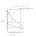
- a common feature of all gas defrost systems is the requirement that the condensing temperature must be substantially greater than 0°C (32F), the melting point of frost, This elevated condensing temperature is necessary to adequately transfer heat to the evaporator and complete the defrost process within a short period of time. Based on a review of common refrigeration practice, it is generally perceived that the condensing temperature necessary for effective defrost should be in the range of 27°C (80F). But the potential efficiency improvement achieved by a low condensing temperature is substantial, as shown by FIG 2 which provides a graphical presentation of efficiency as a function of condensing temperature.
- FIG 2 delineates efficiency in terms of Coefficient of Performance (COP) which is calculated as the dimensionless ratio of the refrigeration effect divided by the compressor power.
- COP Coefficient of Performance
- Gas defrost offers a fast and efficient method of defrost for fluid cooled refrigeration units but a problem remains in reconciling the optimum condenser fluid temperature. Specifically, if the condenser fluid temperature is too low, generally lower than 27°C (80F), the duration of the defrost process will be impractically long. But if the condensing water temperature is maintained at a high level, then the thermodynamic efficiency of the refrigeration unit will be compromised.
- the present invention strives to replace the condenser fluid during the defrost process with a distinctly warm fluid having an elevated temperature suitable for fast and effective gas defrosting. in this manner, a cool fluid can be applied to the condenser during the refrigeration process and thus achieve the highest possible thermodynamic efficiency but a distinctly warm fluid can be applied to the condenser during the defrost process to achieve a fast and effective gas defrost. Since the distinctly warm fluid is used to facilitate the defrost process, it is termed the defrost fluid for the purpose of disclosing the present invention. The present invention also strives to maintain the temperature of the distinctly warm fluid by energy efficient means, most notably means which are more efficient than the electrical resistance means commonly employed for standard-practice electric defrost.
- the present invention implements additional components relative to standard practice, specifically an energy-efficiency heater for maintaining the defrost fluid at an elevated temperature, conduits for transferring the defrost fluid to and from the stated heat exchangers, a pump for forcing the defrost fluid through the pipes and valves for guiding the condenser fluid to each condenser during the refrigeration mode and guiding the defrost fluid to each condenser during the defrost mode.
- the refrigeration units can operate with a low condensing temperature during refrigeration mode to achieve a high thermodynamic efficiency and the refrigeration units can utilize a high temperature defrost fluid during defrost mode to facilitate a fast and effective defrost.
- a system for defrosting refrigeration units comprised of:
- the temperature of said defrost fluid may equal or exceed 27°C (80F).
- the chemical composition of said condenser fluid and said defrost fluid may be identical.
- system may further comprise:
- the superheat sensing function of said expansion valve may be positioned between said heat exchanger and said compressor.
- temperature of said defrost fluid may be maintained by heating means which have a higher efficiency relative to electric resistance heating.
- FIG 3 reveals a novel system for cooling and defrosting either a single or multiple fluid-cooled refrigeration units. Understanding of the present invention is further enhanced FIG 4 and FIG 5 which explain the gas defrost process for an individual fluid cooled refrigeration unit with the implementation of the present invention.
- FIG 3 shows the present invention applied to a system of either a single or multiple fluid-cooled refrigeration units.
- additional components are employed for the purpose of applying a warm defrost fluid during the defrost mode. Since the warm defrost fluid is used to facilitate the defrost process, this fluid is termed defrost fluid 110.
- Defrost fluid 110 is maintained at an elevated temperature by defrost fluid heater 108.
- Defrost fluid heater 108 is a common-practice fluid heater. In its most basic form, defrost fluid heater 108 is an electric water heater.
- defrost fluid heater would ideally be as energy efficient as possible.
- Many fluid heating methods are readily available which provide a higher efficiency than an electric water heater, for example gas-fired water heaters, heat-pump type water heater and refrigeration heat recovery system.
- defrost fluid return pipe 107 is connected to the inlet of defrost fluid heater 108.
- Defrost fluid heater 108 is designed to heat defrost fluid 110 to a temperature suitable for gas defrost, ideally greater than 27°C (80F).
- the outlet of defrost fluid heater 108 is connected to the inlet of defrost fluid pump 109.
- the outlet of defrost fluid pump 109 is connected to defrost fluid supply pipe 106.
- Defrost fluid supply pipe 106, defrost fluid return pipe 107, defrost fluid heater 108 and defrost fluid pump 109 are filled with defrost fluid 110, which is a common heat transfer liquid such as water or glycol.
- Each refrigeration unit contains a condenser 13 which must reject heat away from the refrigeration unit during the refrigeration process and this heat is typically called the "heat-of-rejection".
- Condenser 13 is a heat exchanger with a refrigerant-side and a fluid-side.
- the fluid inlet for condenser 13 for each refrigeration unit is connected to either condenser fluid supply pipe 100 or defrost fluid supply pipe 106 by the function of valve 111.
- Valve 111 is a two-position type and can be actuated by any means (for example, manually or electrically actuated). Valve 111 has two inlets and one outlet. The outlet of valve 111 is connected to the fluid inlet of condenser 13.
- valve 111 One inlet of valve 111 is connected to condenser fluid supply pipe 100.
- the second inlet of valve 111 is connected to defrost fluid supply pipe 106.
- valve 111 When valve 111 is in the position marked “C”, flow is allowed from condenser fluid supply pipe 100 to the fluid inlet of condenser 13.
- valve 111 When valve 111 is in the second position marked “D”, flow is allowed from defrost fluid supply pipe 106 to the fluid inlet of condenser 13.
- Valve 112 is a two-position type and can be actuated by any means. Valve 112 has one inlet and two outlets. The inlet of valve 112 is connected to the fluid outlet of condenser 13. One outlet of valve 112 is connected to condenser fluid return pipe 101. The second outlet of valve 112 is connected to defrost fluid return pipe 107.
- valve 112 is in the first position marked "C”
- flow is allowed from the fluid outlet of condenser 13 to condenser fluid return pipe 101.
- valve 112 is in the second position marked "D”
- flow is allowed from the fluid outlet of condenser 13 to defrost fluid return pipe 107.
- the condenser fluid return pipe 101 is connected to the inlet of cooling unit 102.
- Cooling unit 102 is a fluid chiller, cooling tower or similar cooling device.
- the outlet of cooling unit 102 is connected to the inlet of condenser fluid pump 103.
- the outlet of condenser fluid pump 103 is connected to the condenser fluid supply pipe 100.
- Each condenser 13, condenser fluid supply pipe 100, condenser fluid return pipe 101, cooling unit 102 and condenser fluid pump 103 are filled with condenser fluid 104.
- Condenser fluid 104 has the identical composition as defrost fluid 110 and therefore incidental mixing of the two fluid has does alter the composition of the fluids. Then, when condenser fluid pump 103 is energized, condenser fluid 104 recirculates between condensers 13 to cooling unit 102 and thus transfers the heat-of-rejection away from condensers 13 to cooling unit 102.
- the basic operation of the preferred embodiment as shown by FIG 3 is now described. It is first noted that two modes of operation are required for each refrigeration unit.
- the first mode-of-operation is termed the refrigeration mode and refers to the function of providing useful cooling.
- the second mode-of-operation is termed the defrost mode and refers to the process of removing frost from the evaporator.
- valves 111 and valves 112 are in the "C" position and thus condenser fluid 104 is forced by condenser fluid pump 103 to recirculate from condenser fluid supply pipe 100 to condenser 13 to condenser fluid return pipe 101 and then to cooling unit 102. In this manner, the heat-of-rejection from condenser 13 is transferred to cooling unit 102 as required by the refrigeration process.
- defrost fluid heater 108 maintains defrost fluid 110 at an elevated temperature required for gas defrost.
- valves 111 and valves 112 are switched from the "C" position to the "D" position and thus defrost fluid 110 is forced by defrost fluid pump 109 to recirculate from defrost fluid supply pipe 106 to condenser 13 to defrost fluid return pipe 107 and then to defrost fluid heater 108. In this manner, the distinctly warm defrost fluid is applied to condenser 13 to accomplish a fast and effective gas defrost.
- defrost heat exchanger 105 can be inserted into the standard refrigeration unit.
- the fluid inlet for defrost heat exchanger 105 for each refrigeration unit is connected to defrost fluid supply pipe 106 by the function of valve 113.
- Valve 113 is a two-position type and can be actuated by any means.
- Valve 113 has one inlet and one outlet. The outlet of valve 113 is connected to the fluid inlet of defrost heat exchanger 105.
- defrost heat exchanger 105 The fluid outlet for defrost heat exchanger 105 for each refrigeration unit is connected to defrost fluid return pipe 107.
- valve 113 opens and defrost fluid 110 is forced by defrost fluid pump 109 to recirculate from defrost fluid supply pipe 106 to defrost heat exchanger 105 to defrost fluid return pipe 107 and then to defrost fluid heater 108.
- the high temperature defrost fluid is applied to defrost heat exchanger 105 as well as condenser 13 to accomplish an even faster and more effective gas defrost.
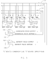
- FIG 4 shows the implementation of the present invention applied to an individual fluid-cooled refrigeration unit which uses gas defrost.
- compressor 10 transfers refrigerant vapor from evaporator 11 to condenser 13.
- Evaporator 11 is connected to compressor 10 with pipe 15.
- Evaporator 11 is a heat exchanger which absorbs heat from the surrounding air. The surrounding air traverses evaporator 11 using fan 12.
- Compressor 10 is connected to condenser 13 with pipe 16. Inserted into pipe 15 is defrost heat exchanger 105.
- valve 113 The fluid inlet for defrost heat exchanger 105 is connected to defrost fluid supply pipe 106 by the function of valve 113.
- Valve 113 is a two-position type and can be actuated by any means.
- Valve 113 has one inlet and one outlet.
- the outlet of valve 113 is connected to the fluid inlet of defrost heat exchanger 105.
- the fluid outlet for defrost heat exchanger 105 for each refrigeration unit is connected to defrost fluid return pipe 107.
- valve 111 is a two-position type and can be actuated by any means. Valve 111 has two inlets and one outlet. The outlet of valve 111 is connected to the fluid inlet of condenser 13. One inlet of valve 111 is connected to condenser fluid supply pipe 100. The second inlet of valve 111 is connected to defrost fluid supply pipe 106.
- valve 111 is in the first position marked "C”
- flow is allowed from condenser fluid supply pipe 100 to the inlet of condenser 13.
- valve 111 is in the second position marked "D”
- flow is allowed from defrost fluid supply pipe 106 to the inlet of condenser 13.
- Valve 112 is a two-position type and can be actuated by any means. Valve 112 has one inlet and two outlets. The inlet of valve 112 is connected to the fluid outlet of condenser 13. One outlet of valve 112 is connected to condenser fluid return pipe 101. The second outlet of valve 112 is connected to defrost fluid return pipe 107.
- valve 112 is in the first position marked "C”
- flow is allowed from the fluid outlet of condenser 13 to condenser fluid return pipe 101.
- valve 112 is in the second position marked "D”
- flow is allowed from the fluid outlet of condenser 13 to defrost fluid return pipe 107.
- Refrigerant can be transferred to evaporator 11 along two alternate paths, marked on FIG 4 as "A" and "B".
- condenser 13 is connected to valve 18 with pipe 17.
- Valve 18 is connected to receiver 20 with pipe 19.
- Valve 18 is of the two-position type (either open or closed) and can be actuated by any means.
- Receiver 20 is a storage vessel of sufficient size to store all of the liquid refrigerant within the refrigeration system.
- Receiver 20 is connected to valve 22 with pipe 21.
- Valve 22 is of the two-position type and can be actuated by any means.
- Valve 22 is connected to expansion valve 24 with pipe 23. Expansion valve 24 is connected to evaporator 11 with pipe 25.
- a continuous path "A” is formed from condenser 13 to evaporator 11 by the sequential connection of parts 17-18-19-20-21-22-23-24-25.
- condenser 13 is connected to valve 27 with pipe 26.
- Valve 27 is of the two-position type (either open or closed) and can be actuated by any means.
- Valve 27 is connected to evaporator 11 with pipe 28.
- an alternate continuous path "B” is formed from condenser 13 to evaporator 11 by the sequential connection of parts 26-27-28.
- compressor 10 pressurizes refrigerant vapor to a hot, high-pressure state.
- the high-pressure vapor then flows to condenser 13.
- Valve 111 and valve 112 are in the position marked as "C" and therefore condenser fluid 104 traverses condenser 13, causing heat to flow from the high-pressure vapor to the condenser fluid 104 and subsequently causing the high-pressure vapor to condense into a high-pressure liquid.
- Valve 113 is closed and therefore defrost fluid 110 is prevented from traversing defrost heat exchanger 105 since the introduction of heat from defrost fluid 110 would be detrimental to the refrigerant process.
- Valve 18 and valve 22 are open and therefore the high pressure liquid is allowed to flow to evaporator 11 along path "A".
- Valve 27 is closed and therefore flow is prevented along Path "B".
- expansion valve 24 imparts a significant loss in pressure to the high-pressure liquid, causing the high-pressure liquid to expand to cold low-pressure mixture of liquid and vapor before entering evaporator 11.
- the surrounding air traverses evaporator 11 using energized fan 12, causing heat to flow from the surrounding air to the cold low-pressure mixture of liquid and vapor, causing the mixture to transition to cold low-pressure vapor.
- the cold low-pressure vapor travels to compressor 10 through pipe 15.
- the cold low-pressure vapor is then re-compressed to hot, high-pressure vapor to complete the refrigeration cycle.
- frost can form on the outside surface of evaporator 11 if the outside surface of evaporator 11 is below the freezing point of water and the surrounding air contains water vapor. This formation of frost will eventually impede the surrounding air from traversing evaporator 11 and thus becomes an impediment to the transfer of heat. At this point in time, the frost must be removed from evaporator 11 with a process typically called "defrosting".
- Gas defrosting is accomplished by implementing two distinct steps:
- Defrost Step #1 is terminated and then Defrost Step #2 is initiated by switching valve 111 and valve 112 to the position marked as “D", closing valve 18, opening valve 27, opening valve 22 and de-energizing fan 12.
- valve 111 and valve 112 in the "D" position, warm defrost fluid 110 transverses condenser 13.
- valve 18 With valve 18 closed, liquid refrigerant stored in receiver 20 is not allowed to leave receiver 20 through pipe 19.
- valve 27 open refrigerant vapor can freely recirculate from condenser 13 to evaporator 11 to compressor 10 along Path "B".
- defrost fluid 110 which traverses condenser 13 is substantially warmer than evaporator 11 in its frosted state and therefore heat is transferred from defrost fluid 110 to the refrigerant vapor as the refrigerant vapor flows through condenser 13 and then from the refrigerant vapor to evaporator 11 as the refrigerant vapor flows through evaporator 11.
- expansion valve 24 With the opening of valve 22, high pressure liquid refrigerant is allowed to flow to expansion valve 24 and subsequently expansion valve 24 introduces liquid refrigerant into the refrigerant vapor recirculating from condenser 13 to evaporator 11 to compressor 10. Since the stated recirculating refrigerant vapor is in a superheated state, the liquid refrigerant introduced by expansion valve 24 is vaporized. By virtue of its purposeful design, expansion valve 24 introduces liquid refrigerant into the stated recirculating refrigerant vapor only as required to maintain the vapor traveling to compressor 10 in a slightly superheated state and thus compressor 10 remains protected from damage due to receiving refrigerant in the liquid state. Defrost Step #2 is terminated when all of frost has been removed from evaporator 11.
- Defrost Step#2 process can be enhanced by opening valve 113, thus allowing fluid warm defrost fluid 110 to transverse defrost heat exchanger 105 and further warm the stated recirculating refrigerant vapor. It is also now revealed that the placement of defrost heat exchanger 105 prior to the superheat sensing function of expansion valve 24 increases the superheated state of the refrigerant vapor as sensed by expansion valve 24. To compensate for the increased superheated state, expansion valve 24 further introduces liquid refrigerant into the refrigerant vapor, thereby increasing the density of the refrigerant vapor and subsequently increasing the transfer of heat from defrost fluid 110 to evaporator 11.
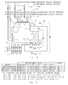
- FIG 5 delineates the sequence of events in tabular form for the gas defrost method with the implementation of the present invention.
- Three distinct modes of operations are shown: normal refrigeration and the two steps of defrost.
- compressor 10 is energized, fan 12 is energized, valve 111 is in the "C” position, valve 112 is in the “C” position, valve 113 is closed, valve 18 is open, valve 22 is open and valve 27 is closed.
- Normal refrigeration is terminated and Defrost Step #1 is initiated when excessive frost has accumulated on the outside surface of evaporator 11.
- Defrost Step #1 is initiated by closing valve 22.
- Defrost Step #1 is terminated and Defrost Step #2 is initiated when all of the liquid refrigerant is stored within receiver 20.
- Defrost Step #2 is initiated by de-energizing fan 12, switching valve 111 to the "D” position, switching valve 112 to the “D” position, opening valve 113, closing valve 18, opening valve 22 and opening valve 27. Defrost Step #2 is terminated and the system returns to normal refrigeration when all of the frost has been removed from evaporator 11.
- the preferred embodiment of the present invention provides a gas-defrost system applicable to fluid-cooled refrigeration units which can operate with a low temperature condensing fluid during refrigeration mode and thus achieve a high thermodynamic efficiency but also can utilize a distinctly warm defrost fluid during defrost mode and thus accomplish a fast and effective defrost.
- the preferred embodiment of the present invention can be readily implemented with basic, well-understood components and therefore deemed to be practical and commercially viable.
Landscapes
- Engineering & Computer Science (AREA)
- Physics & Mathematics (AREA)
- Mechanical Engineering (AREA)
- Thermal Sciences (AREA)
- General Engineering & Computer Science (AREA)
- Chemical & Material Sciences (AREA)
- Combustion & Propulsion (AREA)
- Defrosting Systems (AREA)
Applications Claiming Priority (1)
| Application Number | Priority Date | Filing Date | Title |
|---|---|---|---|
| US13/910,878 US9464840B2 (en) | 2013-06-05 | 2013-06-05 | Gas defrosting system for refrigeration units using fluid cooled condensers |
Publications (2)
| Publication Number | Publication Date |
|---|---|
| EP2811245A2 true EP2811245A2 (de) | 2014-12-10 |
| EP2811245A3 EP2811245A3 (de) | 2015-05-06 |
Family
ID=50884241
Family Applications (1)
| Application Number | Title | Priority Date | Filing Date |
|---|---|---|---|
| EP20140170264 Withdrawn EP2811245A3 (de) | 2013-06-05 | 2014-05-28 | Gasabtausystem für Kühleinheiten mit flüssigkeitsgekühlten Kondensatoren |
Country Status (4)
| Country | Link |
|---|---|
| US (1) | US9464840B2 (de) |
| EP (1) | EP2811245A3 (de) |
| CA (1) | CA2852818C (de) |
| MX (1) | MX347074B (de) |
Families Citing this family (5)
| Publication number | Priority date | Publication date | Assignee | Title |
|---|---|---|---|---|
| AU2009224115B2 (en) * | 2008-03-10 | 2014-09-04 | Hot Water Ip Limited | Heat pump water heater |
| CN104776578B (zh) * | 2015-04-10 | 2018-05-15 | 铨高科技(珠海)股份有限公司 | 空调载冷剂处理系统 |
| ITUB20153364A1 (it) * | 2015-09-03 | 2017-03-03 | Begafrost S R L | Sistema per lo sbrinamento dell?evaporatore esterno in un impianto a pompa di calore. |
| US11493260B1 (en) | 2018-05-31 | 2022-11-08 | Thermo Fisher Scientific (Asheville) Llc | Freezers and operating methods using adaptive defrost |
| WO2020235058A1 (ja) * | 2019-05-22 | 2020-11-26 | 三菱電機株式会社 | 空気調和装置および熱媒体流量算出方法 |
Citations (6)
| Publication number | Priority date | Publication date | Assignee | Title |
|---|---|---|---|---|
| US3636723A (en) | 1969-09-17 | 1972-01-25 | Kramer Trenton Co | Refrigeration system with suction line accumulator |
| US4280335A (en) | 1979-06-12 | 1981-07-28 | Tyler Refrigeration Corporation | Icebank refrigerating and cooling systems for supermarkets |
| US4318277A (en) | 1978-10-02 | 1982-03-09 | Carrier Corporation | Non-reverse hot gas defrost system |
| US4732007A (en) | 1986-12-23 | 1988-03-22 | Gas Research Institute | Auxiliary thermal interface to cooling/heating systems |
| US5335508A (en) | 1991-08-19 | 1994-08-09 | Tippmann Edward J | Refrigeration system |
| US5440894A (en) | 1993-05-05 | 1995-08-15 | Hussmann Corporation | Strategic modular commercial refrigeration |
Family Cites Families (9)
| Publication number | Priority date | Publication date | Assignee | Title |
|---|---|---|---|---|
| EP1475576A4 (de) * | 2002-02-12 | 2009-12-09 | Panasonic Corp | Wassererhitzer für wärmepumpe |
| US7228692B2 (en) * | 2004-02-11 | 2007-06-12 | Carrier Corporation | Defrost mode for HVAC heat pump systems |
| JP4284290B2 (ja) * | 2005-03-24 | 2009-06-24 | 日立アプライアンス株式会社 | ヒートポンプ給湯機 |
| JP3876911B2 (ja) * | 2005-06-29 | 2007-02-07 | ダイキン工業株式会社 | 給湯装置 |
| US20110083462A1 (en) * | 2008-04-24 | 2011-04-14 | Vkr Holding A/S | Device for obtaining heat |
| US8973379B2 (en) | 2008-07-25 | 2015-03-10 | Hill Phoenix, Inc. | Refrigeration control systems and methods for modular compact chiller units |
| JP5713536B2 (ja) * | 2009-01-05 | 2015-05-07 | 三菱電機株式会社 | ヒートポンプ式給湯器 |
| KR101608538B1 (ko) * | 2009-12-31 | 2016-04-01 | 엘지전자 주식회사 | 냉매사이클 연동 물 순환 시스템 |
| DE102011079907A1 (de) | 2011-07-27 | 2013-01-31 | Osram Ag | Leuchtstoffvorrichtung zur konversion von pumplicht |
-
2013
- 2013-06-05 US US13/910,878 patent/US9464840B2/en active Active
-
2014
- 2014-05-28 EP EP20140170264 patent/EP2811245A3/de not_active Withdrawn
- 2014-05-29 CA CA2852818A patent/CA2852818C/en active Active
- 2014-05-30 MX MX2014006564A patent/MX347074B/es active IP Right Grant
Patent Citations (6)
| Publication number | Priority date | Publication date | Assignee | Title |
|---|---|---|---|---|
| US3636723A (en) | 1969-09-17 | 1972-01-25 | Kramer Trenton Co | Refrigeration system with suction line accumulator |
| US4318277A (en) | 1978-10-02 | 1982-03-09 | Carrier Corporation | Non-reverse hot gas defrost system |
| US4280335A (en) | 1979-06-12 | 1981-07-28 | Tyler Refrigeration Corporation | Icebank refrigerating and cooling systems for supermarkets |
| US4732007A (en) | 1986-12-23 | 1988-03-22 | Gas Research Institute | Auxiliary thermal interface to cooling/heating systems |
| US5335508A (en) | 1991-08-19 | 1994-08-09 | Tippmann Edward J | Refrigeration system |
| US5440894A (en) | 1993-05-05 | 1995-08-15 | Hussmann Corporation | Strategic modular commercial refrigeration |
Also Published As
| Publication number | Publication date |
|---|---|
| MX347074B (es) | 2017-04-10 |
| US20140360216A1 (en) | 2014-12-11 |
| MX2014006564A (es) | 2014-12-05 |
| US9464840B2 (en) | 2016-10-11 |
| CA2852818C (en) | 2018-02-27 |
| CA2852818A1 (en) | 2014-12-05 |
| EP2811245A3 (de) | 2015-05-06 |
Similar Documents
| Publication | Publication Date | Title |
|---|---|---|
| US6170270B1 (en) | Refrigeration system using liquid-to-liquid heat transfer for warm liquid defrost | |
| JP5327308B2 (ja) | 給湯空調システム | |
| JP5934257B2 (ja) | フラッシュ(flash)除霜システム | |
| CA2615689C (en) | An air conditioning heat pump with secondary compressor | |
| US6094925A (en) | Crossover warm liquid defrost refrigeration system | |
| EP2420767B1 (de) | Wärmepumpenwasserversorgungs- und Klimaanlagevorrichtung | |
| US9746221B2 (en) | Defrost system for refrigeration apparatus, and cooling unit | |
| EP2410249B1 (de) | Warmwassereinspeisungsvorrichtung mit Wärmepumpe | |
| US20090173091A1 (en) | Multi-range composite-evaporator type cross-defrosting system | |
| JP2008256304A (ja) | 冷凍装置 | |
| CA2852818C (en) | Gas defrosting system for refrigeration units using fluid cooled condensers | |
| EP2645019B1 (de) | Wärmepumpenartige warmwasserversorgungsvorrichtung | |
| KR20120125857A (ko) | 이원냉동사이클을 갖는 축열장치 및 그 운전방법 | |
| JP5842310B2 (ja) | 冷凍装置、および負荷冷却器のデフロスト方法 | |
| JP2012163219A (ja) | ヒートポンプシステム | |
| US20170211871A1 (en) | Sealed System and a Method For Defrosting an Evaporator | |
| JP2013083439A (ja) | 給湯空調システム | |
| JP2013083439A5 (de) | ||
| US10443913B2 (en) | Refrigerator and method for controlling the same | |
| KR101272021B1 (ko) | 이원 사이클 히트펌프 냉난방 장치 | |
| JP4869320B2 (ja) | 冷凍サイクル装置及びこれを搭載した給湯機 | |
| KR101979577B1 (ko) | 히트펌프 시스템 | |
| JP6119804B2 (ja) | 負荷冷却器のデフロスト方法 | |
| JP2007102680A (ja) | 自動販売機 | |
| JP2016142483A (ja) | 空気冷却器 |
Legal Events
| Date | Code | Title | Description |
|---|---|---|---|
| PUAI | Public reference made under article 153(3) epc to a published international application that has entered the european phase |
Free format text: ORIGINAL CODE: 0009012 |
|
| 17P | Request for examination filed |
Effective date: 20140528 |
|
| AK | Designated contracting states |
Kind code of ref document: A2 Designated state(s): AL AT BE BG CH CY CZ DE DK EE ES FI FR GB GR HR HU IE IS IT LI LT LU LV MC MK MT NL NO PL PT RO RS SE SI SK SM TR |
|
| AX | Request for extension of the european patent |
Extension state: BA ME |
|
| PUAL | Search report despatched |
Free format text: ORIGINAL CODE: 0009013 |
|
| AK | Designated contracting states |
Kind code of ref document: A3 Designated state(s): AL AT BE BG CH CY CZ DE DK EE ES FI FR GB GR HR HU IE IS IT LI LT LU LV MC MK MT NL NO PL PT RO RS SE SI SK SM TR |
|
| AX | Request for extension of the european patent |
Extension state: BA ME |
|
| RIC1 | Information provided on ipc code assigned before grant |
Ipc: F25D 21/12 20060101AFI20150327BHEP Ipc: F25B 47/02 20060101ALI20150327BHEP |
|
| R17P | Request for examination filed (corrected) |
Effective date: 20151105 |
|
| RBV | Designated contracting states (corrected) |
Designated state(s): AL AT BE BG CH CY CZ DE DK EE ES FI FR GB GR HR HU IE IS IT LI LT LU LV MC MK MT NL NO PL PT RO RS SE SI SK SM TR |
|
| 17Q | First examination report despatched |
Effective date: 20170821 |
|
| STAA | Information on the status of an ep patent application or granted ep patent |
Free format text: STATUS: THE APPLICATION IS DEEMED TO BE WITHDRAWN |
|
| 18D | Application deemed to be withdrawn |
Effective date: 20181201 |