EP2811249A1 - Einheitliche Wärmetauscher mit einstückigen nachgiebigen Wärmetauscherrohren und Wärmetauschersysteme damit - Google Patents
Einheitliche Wärmetauscher mit einstückigen nachgiebigen Wärmetauscherrohren und Wärmetauschersysteme damit Download PDFInfo
- Publication number
- EP2811249A1 EP2811249A1 EP14176161.9A EP14176161A EP2811249A1 EP 2811249 A1 EP2811249 A1 EP 2811249A1 EP 14176161 A EP14176161 A EP 14176161A EP 2811249 A1 EP2811249 A1 EP 2811249A1
- Authority
- EP
- European Patent Office
- Prior art keywords
- heat exchanger
- integrally
- unitary
- formed compliant
- integral
- Prior art date
- Legal status (The legal status is an assumption and is not a legal conclusion. Google has not performed a legal analysis and makes no representation as to the accuracy of the status listed.)
- Granted
Links
Images







Classifications
-
- F—MECHANICAL ENGINEERING; LIGHTING; HEATING; WEAPONS; BLASTING
- F28—HEAT EXCHANGE IN GENERAL
- F28D—HEAT-EXCHANGE APPARATUS, NOT PROVIDED FOR IN ANOTHER SUBCLASS, IN WHICH THE HEAT-EXCHANGE MEDIA DO NOT COME INTO DIRECT CONTACT
- F28D1/00—Heat-exchange apparatus having stationary conduit assemblies for one heat-exchange medium only, the media being in contact with different sides of the conduit wall, in which the other heat-exchange medium is a large body of fluid, e.g. domestic or motor car radiators
- F28D1/02—Heat-exchange apparatus having stationary conduit assemblies for one heat-exchange medium only, the media being in contact with different sides of the conduit wall, in which the other heat-exchange medium is a large body of fluid, e.g. domestic or motor car radiators with heat-exchange conduits immersed in the body of fluid
- F28D1/04—Heat-exchange apparatus having stationary conduit assemblies for one heat-exchange medium only, the media being in contact with different sides of the conduit wall, in which the other heat-exchange medium is a large body of fluid, e.g. domestic or motor car radiators with heat-exchange conduits immersed in the body of fluid with tubular conduits
- F28D1/053—Heat-exchange apparatus having stationary conduit assemblies for one heat-exchange medium only, the media being in contact with different sides of the conduit wall, in which the other heat-exchange medium is a large body of fluid, e.g. domestic or motor car radiators with heat-exchange conduits immersed in the body of fluid with tubular conduits the conduits being straight
- F28D1/05316—Assemblies of conduits connected to common headers, e.g. core type radiators
-
- F—MECHANICAL ENGINEERING; LIGHTING; HEATING; WEAPONS; BLASTING
- F16—ENGINEERING ELEMENTS AND UNITS; GENERAL MEASURES FOR PRODUCING AND MAINTAINING EFFECTIVE FUNCTIONING OF MACHINES OR INSTALLATIONS; THERMAL INSULATION IN GENERAL
- F16L—PIPES; JOINTS OR FITTINGS FOR PIPES; SUPPORTS FOR PIPES, CABLES OR PROTECTIVE TUBING; MEANS FOR THERMAL INSULATION IN GENERAL
- F16L27/00—Adjustable joints; Joints allowing movement
- F16L27/10—Adjustable joints; Joints allowing movement comprising a flexible connection only
- F16L27/107—Adjustable joints; Joints allowing movement comprising a flexible connection only the ends of the pipe being interconnected by a flexible sleeve
- F16L27/11—Adjustable joints; Joints allowing movement comprising a flexible connection only the ends of the pipe being interconnected by a flexible sleeve the sleeve having the form of a bellows with multiple corrugations
-
- F—MECHANICAL ENGINEERING; LIGHTING; HEATING; WEAPONS; BLASTING
- F28—HEAT EXCHANGE IN GENERAL
- F28D—HEAT-EXCHANGE APPARATUS, NOT PROVIDED FOR IN ANOTHER SUBCLASS, IN WHICH THE HEAT-EXCHANGE MEDIA DO NOT COME INTO DIRECT CONTACT
- F28D7/00—Heat-exchange apparatus having stationary tubular conduit assemblies for both heat-exchange media, the media being in contact with different sides of a conduit wall
- F28D7/0058—Heat-exchange apparatus having stationary tubular conduit assemblies for both heat-exchange media, the media being in contact with different sides of a conduit wall the conduits for only one medium being tubes having different orientations to each other or crossing the conduit for the other heat exchange medium
-
- F—MECHANICAL ENGINEERING; LIGHTING; HEATING; WEAPONS; BLASTING
- F28—HEAT EXCHANGE IN GENERAL
- F28F—DETAILS OF HEAT-EXCHANGE AND HEAT-TRANSFER APPARATUS, OF GENERAL APPLICATION
- F28F1/00—Tubular elements; Assemblies of tubular elements
- F28F1/006—Tubular elements; Assemblies of tubular elements with variable shape, e.g. with modified tube ends, with different geometrical features
-
- F—MECHANICAL ENGINEERING; LIGHTING; HEATING; WEAPONS; BLASTING
- F28—HEAT EXCHANGE IN GENERAL
- F28F—DETAILS OF HEAT-EXCHANGE AND HEAT-TRANSFER APPARATUS, OF GENERAL APPLICATION
- F28F1/00—Tubular elements; Assemblies of tubular elements
- F28F1/08—Tubular elements crimped or corrugated in longitudinal section
-
- F—MECHANICAL ENGINEERING; LIGHTING; HEATING; WEAPONS; BLASTING
- F28—HEAT EXCHANGE IN GENERAL
- F28F—DETAILS OF HEAT-EXCHANGE AND HEAT-TRANSFER APPARATUS, OF GENERAL APPLICATION
- F28F1/00—Tubular elements; Assemblies of tubular elements
- F28F1/10—Tubular elements and assemblies thereof with means for increasing heat-transfer area, e.g. with fins, with projections, with recesses
-
- F—MECHANICAL ENGINEERING; LIGHTING; HEATING; WEAPONS; BLASTING
- F28—HEAT EXCHANGE IN GENERAL
- F28F—DETAILS OF HEAT-EXCHANGE AND HEAT-TRANSFER APPARATUS, OF GENERAL APPLICATION
- F28F5/00—Elements specially adapted for movement
-
- B—PERFORMING OPERATIONS; TRANSPORTING
- B22—CASTING; POWDER METALLURGY
- B22F—WORKING METALLIC POWDER; MANUFACTURE OF ARTICLES FROM METALLIC POWDER; MAKING METALLIC POWDER; APPARATUS OR DEVICES SPECIALLY ADAPTED FOR METALLIC POWDER
- B22F10/00—Additive manufacturing of workpieces or articles from metallic powder
- B22F10/20—Direct sintering or melting
- B22F10/25—Direct deposition of metal particles, e.g. direct metal deposition [DMD] or laser engineered net shaping [LENS]
-
- B—PERFORMING OPERATIONS; TRANSPORTING
- B22—CASTING; POWDER METALLURGY
- B22F—WORKING METALLIC POWDER; MANUFACTURE OF ARTICLES FROM METALLIC POWDER; MAKING METALLIC POWDER; APPARATUS OR DEVICES SPECIALLY ADAPTED FOR METALLIC POWDER
- B22F10/00—Additive manufacturing of workpieces or articles from metallic powder
- B22F10/20—Direct sintering or melting
- B22F10/28—Powder bed fusion, e.g. selective laser melting [SLM] or electron beam melting [EBM]
-
- B—PERFORMING OPERATIONS; TRANSPORTING
- B22—CASTING; POWDER METALLURGY
- B22F—WORKING METALLIC POWDER; MANUFACTURE OF ARTICLES FROM METALLIC POWDER; MAKING METALLIC POWDER; APPARATUS OR DEVICES SPECIALLY ADAPTED FOR METALLIC POWDER
- B22F10/00—Additive manufacturing of workpieces or articles from metallic powder
- B22F10/30—Process control
- B22F10/36—Process control of energy beam parameters
-
- B—PERFORMING OPERATIONS; TRANSPORTING
- B22—CASTING; POWDER METALLURGY
- B22F—WORKING METALLIC POWDER; MANUFACTURE OF ARTICLES FROM METALLIC POWDER; MAKING METALLIC POWDER; APPARATUS OR DEVICES SPECIALLY ADAPTED FOR METALLIC POWDER
- B22F10/00—Additive manufacturing of workpieces or articles from metallic powder
- B22F10/60—Treatment of workpieces or articles after build-up
- B22F10/62—Treatment of workpieces or articles after build-up by chemical means
-
- B—PERFORMING OPERATIONS; TRANSPORTING
- B22—CASTING; POWDER METALLURGY
- B22F—WORKING METALLIC POWDER; MANUFACTURE OF ARTICLES FROM METALLIC POWDER; MAKING METALLIC POWDER; APPARATUS OR DEVICES SPECIALLY ADAPTED FOR METALLIC POWDER
- B22F10/00—Additive manufacturing of workpieces or articles from metallic powder
- B22F10/60—Treatment of workpieces or articles after build-up
- B22F10/64—Treatment of workpieces or articles after build-up by thermal means
-
- B—PERFORMING OPERATIONS; TRANSPORTING
- B22—CASTING; POWDER METALLURGY
- B22F—WORKING METALLIC POWDER; MANUFACTURE OF ARTICLES FROM METALLIC POWDER; MAKING METALLIC POWDER; APPARATUS OR DEVICES SPECIALLY ADAPTED FOR METALLIC POWDER
- B22F10/00—Additive manufacturing of workpieces or articles from metallic powder
- B22F10/60—Treatment of workpieces or articles after build-up
- B22F10/66—Treatment of workpieces or articles after build-up by mechanical means
-
- F—MECHANICAL ENGINEERING; LIGHTING; HEATING; WEAPONS; BLASTING
- F28—HEAT EXCHANGE IN GENERAL
- F28D—HEAT-EXCHANGE APPARATUS, NOT PROVIDED FOR IN ANOTHER SUBCLASS, IN WHICH THE HEAT-EXCHANGE MEDIA DO NOT COME INTO DIRECT CONTACT
- F28D21/00—Heat-exchange apparatus not covered by any of the groups F28D1/00 - F28D20/00
- F28D2021/0019—Other heat exchangers for particular applications; Heat exchange systems not otherwise provided for
- F28D2021/0021—Other heat exchangers for particular applications; Heat exchange systems not otherwise provided for for aircrafts or cosmonautics
-
- F—MECHANICAL ENGINEERING; LIGHTING; HEATING; WEAPONS; BLASTING
- F28—HEAT EXCHANGE IN GENERAL
- F28D—HEAT-EXCHANGE APPARATUS, NOT PROVIDED FOR IN ANOTHER SUBCLASS, IN WHICH THE HEAT-EXCHANGE MEDIA DO NOT COME INTO DIRECT CONTACT
- F28D7/00—Heat-exchange apparatus having stationary tubular conduit assemblies for both heat-exchange media, the media being in contact with different sides of a conduit wall
- F28D7/16—Heat-exchange apparatus having stationary tubular conduit assemblies for both heat-exchange media, the media being in contact with different sides of a conduit wall the conduits being arranged in parallel spaced relation
-
- F—MECHANICAL ENGINEERING; LIGHTING; HEATING; WEAPONS; BLASTING
- F28—HEAT EXCHANGE IN GENERAL
- F28F—DETAILS OF HEAT-EXCHANGE AND HEAT-TRANSFER APPARATUS, OF GENERAL APPLICATION
- F28F1/00—Tubular elements; Assemblies of tubular elements
- F28F1/10—Tubular elements and assemblies thereof with means for increasing heat-transfer area, e.g. with fins, with projections, with recesses
- F28F1/12—Tubular elements and assemblies thereof with means for increasing heat-transfer area, e.g. with fins, with projections, with recesses the means being only outside the tubular element
- F28F1/24—Tubular elements and assemblies thereof with means for increasing heat-transfer area, e.g. with fins, with projections, with recesses the means being only outside the tubular element and extending transversely
- F28F1/26—Tubular elements and assemblies thereof with means for increasing heat-transfer area, e.g. with fins, with projections, with recesses the means being only outside the tubular element and extending transversely the means being integral with the element
-
- F—MECHANICAL ENGINEERING; LIGHTING; HEATING; WEAPONS; BLASTING
- F28—HEAT EXCHANGE IN GENERAL
- F28F—DETAILS OF HEAT-EXCHANGE AND HEAT-TRANSFER APPARATUS, OF GENERAL APPLICATION
- F28F2255/00—Heat exchanger elements made of materials having special features or resulting from particular manufacturing processes
- F28F2255/02—Flexible elements
-
- F—MECHANICAL ENGINEERING; LIGHTING; HEATING; WEAPONS; BLASTING
- F28—HEAT EXCHANGE IN GENERAL
- F28F—DETAILS OF HEAT-EXCHANGE AND HEAT-TRANSFER APPARATUS, OF GENERAL APPLICATION
- F28F2255/00—Heat exchanger elements made of materials having special features or resulting from particular manufacturing processes
- F28F2255/18—Heat exchanger elements made of materials having special features or resulting from particular manufacturing processes sintered
-
- F—MECHANICAL ENGINEERING; LIGHTING; HEATING; WEAPONS; BLASTING
- F28—HEAT EXCHANGE IN GENERAL
- F28F—DETAILS OF HEAT-EXCHANGE AND HEAT-TRANSFER APPARATUS, OF GENERAL APPLICATION
- F28F2265/00—Safety or protection arrangements; Arrangements for preventing malfunction
- F28F2265/26—Safety or protection arrangements; Arrangements for preventing malfunction for allowing differential expansion between elements
-
- Y—GENERAL TAGGING OF NEW TECHNOLOGICAL DEVELOPMENTS; GENERAL TAGGING OF CROSS-SECTIONAL TECHNOLOGIES SPANNING OVER SEVERAL SECTIONS OF THE IPC; TECHNICAL SUBJECTS COVERED BY FORMER USPC CROSS-REFERENCE ART COLLECTIONS [XRACs] AND DIGESTS
- Y02—TECHNOLOGIES OR APPLICATIONS FOR MITIGATION OR ADAPTATION AGAINST CLIMATE CHANGE
- Y02P—CLIMATE CHANGE MITIGATION TECHNOLOGIES IN THE PRODUCTION OR PROCESSING OF GOODS
- Y02P10/00—Technologies related to metal processing
- Y02P10/25—Process efficiency
Definitions
- the present invention generally relates to heat exchange systems, and more particularly relates to unitary heat exchangers having integrally-formed compliant heat exchanger tubes and heat exchange systems including the same.
- Heat exchange is important to ensure machinery and engines such as gas turbine engines remain within acceptable operational parameters as well as to achieve efficient thermodynamic operation.
- a great deal of effort has been directed toward improving thermodynamic efficiency by operating gas turbine engines at increasing temperatures.
- numerous heat exchange systems have been developed for directing heat within an engine to components where such heat is beneficial to the operating performance of the engine, while other heat exchange systems have been developed for directing heat away from engine components that normally cannot tolerate such high temperatures.
- recuperators have been developed to recover heat from the engine exhaust, which is otherwise wasted energy, and redirect the recovered engine exhaust heat to the combustion portion of the engine, to increase its overall efficiency.
- the recuperator transfers some of the waste heat in the exhaust to the compressed air that enters the combustion portion of the engine, thus preheating it before entering the fuel combustor stage. As the compressed air has been preheated, less fuel is needed to heat the compressed air/fuel mixture up to the desired turbine inlet temperature. By recovering some of the energy usually lost as waste heat, the recuperator can make a gas turbine engine significantly more efficient.
- cooling air may be provided to various turbine engine components using cooling air extracted from other parts of the engine.
- cooling air is extracted from the discharge of the compressor, and is then directed to certain portions of the turbine.
- the air that is extracted from the engine for cooling may be at temperatures that require the air to be cooled before being directed to the particular component requiring cooling.
- cooling air may be directed through one or more heat exchangers within the engine.
- Recuperators, cooling air heat exchangers, and other heat exchangers employed in gas turbine engines have been conventionally designed using either plate-fin architectures or tubular architectures.
- Plate-fin architectures while relatively inexpensive to manufacture, do not result in favorable weight and performance characteristics.
- Tubular architectures while relatively more efficient than plate-fin architectures, are often prohibitively expensive to manufacture.
- conventional plate-fin and tubular architectures are susceptible to thermo-mechanical fatigue (TMF), especially at braze connections, as they do not allow adequate thermal growth and stress compliance during transient and steady state operations, reducing their service life and/or necessitating costly repairs.
- TMF thermo-mechanical fatigue
- heat exchanger tubes in conventional heat exchangers with tubular architectures may be rigidly coupled to each other by fins or otherwise, thereby restricting relative motion and inducing detrimental stresses in the heat exchanger.
- unitary heat exchangers having integrally-formed compliant heat exchanger tubes, and heat exchange systems including the same there is also a need for unitary heat exchangers having integrally-formed compliant heat exchanger tubes and heat exchange systems having improved efficiency, reduced manufacturing costs, and increased operating lifespan over conventional heat exchangers, with less fluidic loss for improved engine cycle performance, and less weight.
- the unitary heat exchanger comprises an inlet plenum and an outlet plenum and a plurality of integrally-formed compliant heat exchanger tubes.
- the plurality of integrally-formed compliant heat exchanger tubes extend between and are integral with the inlet and outlet plenums to define a heat exchanger first flow passage.
- Each integrally-formed compliant heat exchanger tube comprises a tubular member and a plurality of integral heat transfer fins extending radially outwardly from at least one portion of the tubular member.
- the tubular member has a proximal tube end and a distal tube end and comprises a tubular wall having an outer wall surface and an inner wall surface.
- Integrally-formed compliant heat exchanger tubes are provided in accordance with yet another exemplary embodiment of the present invention.
- the integrally-formed compliant heat exchanger tube comprises a tubular member having a proximal tube end and a distal tube end and comprising a tubular wall having an outer wall surface and an inner wall surface.
- a plurality of integral heat transfer fins extend radially outwardly from at least one portion of the tubular member.
- An integral bellows portion is formed in a portion of the tubular wall.
- the heat exchange system comprises a unitary heat exchanger including a heat exchanger first flow passage and a heat exchanger second flow passage.
- the heat exchanger first flow passage is configured to receive a first fluid and the heat exchanger second flow passage is configured to receive a second fluid.
- the unitary heat exchanger is configured to transfer heat between the first and second fluids.
- the heat exchanger first flow passage comprises an inlet plenum and an outlet plenum and a plurality of integrally-formed compliant heat exchanger tubes extending between and integral with the inlet and outlet plenums.
- Each integrally-formed compliant heat exchanger tube comprises a tubular member having a proximal tube end and a distal tube end and comprising a tubular wall having an outer wall surface and an inner wall surface.
- a plurality of integral heat transfer fins extend radially outwardly from at least one portion of the tubular member.
- An integral bellows portion is formed in a portion of the tubular wall.
- unitary heat exchangers having integrally-formed compliant heat exchanger tubes and heat exchange systems including the same.
- unitary means one-piece such that the unitary heat exchanger having the plurality of integrally-formed compliant heat exchanger tubes is all one-piece and excludes brazing, fasteners, or the like for maintaining parts in a fixed relationship as a single unit.
- the integrally-formed compliant heat exchanger tubes are not removable or separable from inlet and outlet plenums as hereinafter described.
- integralally-formed and “integral” mean one-piece and excludes brazing, fasteners, or the like for maintaining portions thereon in a fixed relationship as a single unit.
- the terms "compliant” and “compliance” as used herein refer to the ability to absorb and attenuate relative motions to eliminate concentrated stress, thereby minimizing the negative effects of thermo-mechanical fatigue (TMF) during the heat exchange operation as hereinafter described.
- TMF thermo-mechanical fatigue
- the integrally-formed "compliant" heat exchanger tubes are each independent and not rigidly coupled together, by fins or otherwise, thereby permitting their relative motion. This provision for relative movement between adjacent tubes reduces stresses that may occur in the structure if the movement were not permitted. An example of such stresses is thermal stresses due to the steady state and/or transient temperature gradients during heat exchange operation which result in TMF.
- the unitary heat exchangers having integrally-formed compliant heat exchanger tubes and the heat exchange systems including the same allow adequate thermal growth and stress compliance during transient and steady state operations and have improved efficiency, reduced manufacturing costs, and increased operating lifespan over conventional heat exchangers and heat exchange systems, with less fluidic loss for improved engine cycle performance, and less weight.
- the unitary heat exchangers having integrally-formed compliant heat exchanger tubes and heat exchange systems including the same as described herein are suitable for use in gas turbine engines, and other applications.
- the heat exchange system is embodied as a recuperator for heating compressed air prior to the entry thereof into the combustor.
- the heat exchange system is embodied as a cooling air heat exchanger for reducing the temperature of cooling air prior to its delivery to turbine components that require cooling.
- the presently disclosed unitary heat exchangers having integrally-formed compliant heat exchanger tubes and the heat exchange systems including the same are not limited to use in the aforementioned embodiments.
- unitary heat exchangers having integrally-formed compliant heat exchanger tubes and the heat exchange systems including the same disclosed herein will be suitable for use in a wide array of applications.
- Some nonlimiting examples include engine oil cooling, auxiliary power units, environmental control systems, chemical reaction systems, and any other systems where heat exchange between two fluid media is either required or desirable.
- FIG. 1 depicts a simplified cross section view of an exemplary gas turbine engine 100.
- the depicted engine 100 includes an intake section 102, a compressor section 104, a combustion section 106, a turbine section 108, and an exhaust section 112.
- the intake section 102, compressor section 104, combustion section 106, turbine section 108, and exhaust section 112 are all mounted within a nacelle 114.
- the compressor section 104, combustion section 106, and turbine section 108 are all mounted within an engine case 116.
- the intake section 102 includes a fan 118, which draws air into the engine 100 and accelerates it.
- a fraction of the accelerated fan air that is exhausted from the fan 118 is directed through a fan air bypass duct 122 that is defined by an outer fan duct 124 that is spaced apart from and surrounds an inner fan duct 126.
- Most of the fan air that flows through the fan air bypass duct 122 is discharged from the bypass duct 122 to generate a forward thrust.
- the fraction of fan air that does not flow into the fan air bypass duct 122 is directed into the compressor section 104.
- the compressor section 104 can include one or more compressors.
- the engine 100 depicted in FIG. 1 includes two compressors: an intermediate pressure compressor 132 and a high pressure compressor 134. No matter the number of compressors it includes, the air that is directed into the compressor section 104 is pressurized to a relatively high pressure.
- the relatively high pressure air that is discharged from the compressor section 104 is directed into the combustion section 106.
- the combustion section 106 includes a combustor 136 that is coupled to receive both the relatively high pressure air and atomized fuel.
- the relatively high pressure air and atomized fuel are mixed within the combustor 136 and the mixture is ignited to generate combusted air.
- the combusted air is then directed into the turbine section 108.
- the depicted turbine section 108 includes three turbines: a high pressure turbine 138, an intermediate pressure turbine 142, and a low pressure turbine 144, though it should be appreciated that any number of turbines may be included.
- the combusted air directed into the turbine section 108 expands through each of turbines 138, 142, 144, causing each to rotate.
- the air is then exhausted through a propulsion nozzle 146 disposed in the exhaust section 112 to provide additional forward thrust.
- each drives equipment in the gas turbine engine 100 via concentrically disposed shafts or spools as best seen in FIG. 1 .
- the engine 100 additionally includes a cooling air system 200 to provide cooling air to these various portions within the engine 100.
- the cooling air system 200 extracts relatively hot air 202 from within the engine case 116, directs the relatively hot air 202 through a cooling air unitary heat exchanger 204 to be cooled, and then directs the cooled air 206 back into the engine case 116 to provide cooling air to various portions of the engine 100.
- a portion of the fan air 203 in the fan air bypass duct 122 is supplied, via an inlet 214, to the unitary heat exchanger 204.
- the supplied fan air 203 flows through the unitary heat exchanger 204 to cool the relatively hot air 202 that is extracted from the engine case 116, and is then directed back into the fan air bypass duct 122.
- the unitary heat exchanger 204 is configured to transfer heat between the relatively hot air 202 (an exemplary "first fluid") and the fan air (an exemplary "second fluid").
- fan air may be selectively (as opposed to continuously) supplied to the heat exchanger to improve operating performance of the engine, as described in greater detail in commonly-assigned United States Patent Application Serial No. 13/358,161 , titled “GAS TURBINE ENGINE IN-BOARD COOLED COOLING AIR SYSTEM,” filed January 25, 2012, the contents of which are herein incorporated by reference in their entirety.
- the gas turbine engine 100 preferably includes a plurality of unitary heat exchangers 204 (204-1, 204-2, 204-3, ..., 204-8) and a plurality of inlets 214 (214-1, 214-2, 214-3, ... , 214-8) (not all of which are visible in FIG. 3 ).
- Each of the inlets 214 is associated with a different one of the unitary heat exchangers 204.
- the depicted cooling air system is implemented with eight unitary heat exchangers 204 and eight inlets 214, it will be appreciated that this is merely exemplary, and that other numbers of unitary heat exchangers 204 and inlets 214 may be used.
- the unitary heat exchangers 204 are conformal, in that each is disposed within and conforms to the curvature of the inner fan duct 126 and, as shown most clearly in FIG. 5 , the unitary heat exchangers 204 may be coupled together with the inner fan duct 126 to form an annular ring. This configuration minimizes the installation space, minimizes transmission pressure loss, and maximizes the differential pressure across the unitary heat exchanger 204. While FIG. 4A illustrates a conformal unitary heat exchanger with regard to a cooling heat exchanger in a gas turbine engine, other shapes, sizes, and number of unitary heat exchangers are possible to conform to other implementations.
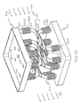
- the unitary heat exchanger 204 is implemented as a tubular bundle type that includes a plurality of integrally-formed compliant heat exchanger tubes 402, a heat exchanger first flow passage 404, and a heat exchanger second flow passage 406.
- the plurality of integrally-formed compliant heat exchanger tubes comprise relatively straight tubes.
- Each heat exchanger first flow passage 404 includes an inlet port 408 in flow communication with an inlet plenum 410, and an outlet plenum 412 in flow communication with an outlet port 414.
- the inlet plenum 410 is defined by an inner wall 417, an outer wall 413, and endwalls. A portion of the outer wall 413 of the inlet plenum has been removed in FIG.
- each integrally-formed compliant heat exchanger tube is associated with a tube inlet 415 (and a tube outlet (not shown), as hereinafter described).
- the outlet plenum 412 is defined by an inner plenum wall 422, an outer plenum wall 416, and endwalls. A plurality of the tube outlets (not shown) are provided in the inner plenum wall 422.
- the outlet plenum 412 is substantially a mirror image of the inlet plenum in the embodiment illustrated in FIG. 4A . An end portion of the outlet plenum has been removed in FIG. 4A .
- the integrally-formed compliant heat exchanger tubes402 extend between and are integral with the inlet and outlet plenums to define the heat exchanger first flow passage.
- Each inlet port 408 is configured to receive the relatively hot air 202 from within the engine case 116, and each heat exchanger second flow passage 406 is configured to receive fan air from the bypass flow passage 122.
- Each heat exchanger second flow passage 406 ( FIG. 4A ) is configured to direct the supplied fan air 203 across the associated tubes 402.
- the unitary heat exchangers 204 can each be configured such that the fan air flow may be either cross flow, counter flow, or a combination of both.
- the tube inlets 415 are smoothly curved or contoured. This curvature or contour reduces inlet flow losses as compared to traditional sharp cornered tube inlets. In some examples, this flow loss can be reduced by as much as 90% by employing curved or contoured tube inlets.
- the tube inlets 415 are also counter-sunk with respect to the flow passage. This counter-sunk design allows for a smooth transition of cooling air from the inlet plenum into the tubes to minimize pressure drops.
- the plurality of inlets are configured to allow the first fluid to flow from the inlet plenum and into the heat exchanger tubes and provide compliance in the transition between the inlet plenum and the respective tube.
- the interface between the inlet plenum and the respective tube may include varying wall thickness features to allow such structural compliance.
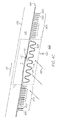
- each integrally-formed compliant heat exchanger tube 402 comprises a tubular member 411 defining a flow path (a portion of the first flow passage) between the proximal tube end 407 and the distal tube end 409, the tubular member 411 defined by a tubular wall 413 ( FIG. 4C ) defining a tube interior 418 comprising the flow path and a tube exterior 420.
- Arrow 419 in FIG. 4C depicts the direction of flow in the tube interior 418 (i.e., in a portion of the first flow passage) and arrow 421 depicts the direction of flow from the tube exterior 420 (i.e., in a portion of the second flow passage).
- the plurality of integrally-formed compliant heat exchanger tubes have substantially coextensive proximal tube ends 407 that may be integrally-formed at the tube inlets with the inlet plenum and substantially coextensive distal tube ends 409 that may be integrally-formed with the outlet plenum at corresponding tube outlets (not shown).
- Each integrally-formed compliant heat exchanger tube 402 ( FIGS. 4B and 4C ) comprises a plurality of integral heat transfer fins 450 extending radially outwardly from at least one portion of the tubular member.
- the plurality of integral heat transfer fins 450 may be arranged in one or more fin groups.
- the integrally-formed compliant heat exchanger tubes of the unitary heat exchanger 204 depicted in FIGS. 4A include a first fin group 452 and a second fin group 454.
- the first and second fin groups 452 and 454 are located proximate the proximal tube end and the distal tube end, respectively.
- the fin groups may be selectively located at axial positions other than as depicted, their optimum position determined bycomputational fluid/heat transfer analysis and by corresponding stress analysis, as commonly performed by one skilled in the art.
- the fins in each fin group may be substantially in parallel relationship with each otheras depicted, for optimal flow performance.
- the spacing between the heat transfer fins within each fin group and relative to other fin groups in the same or a different integrally-formed heat exchanger tube may be the same or different.
- the plurality of integral heat transfer fins are exposed to the supplied fan air 203 in the second flow passage which cools the heat transfer fins, with the high thermal conductivity of the fin material allowing increased heat transfer.
- the integral heat transfer fins may be generally annular in shape as depicted in FIGS. 4A through 4C or may have other shapes and may be selectively oriented to direct fluid flow turning into and out of the plurality of integrally-formed compliant heat exchanger tubes, i.e., to act as inlet and/or outlet (exit) louvers as hereinafter described.
- Fin spacing, locations, and groupings are determined by computational fluid/heat transfer analysis and by corresponding stress analysis to optimize the overall performance of the unitary heat exchanger with respect to pressure drops, heat transfer, stress, and weight.
- unitary heat exchanger 204 is depicted with fourteen fins in two fin groups, it will be appreciated that this is merely exemplary, and that other numbers of fins 450 and fin groups may be used. Similarly, the number of fins and fin groups in other depicted unitary heat exchangers as described herein is merely exemplary, and other numbers of fins and fin groups may be used.
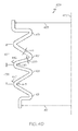
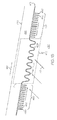
- Each integrally-formed compliant heat exchanger tube 402 further comprises an integral bellows portion 425 (shown best in encircled region A of FIG. 4C ).
- the integral bellows portion 425 may be selectively positioned in substantially a central portion between the first fin group 452 and the second fin group 454, between the inlet and outlet plenums in the unitary heat exchanger 204.
- Finite element analysis and different aero/thermal/stress modeling tools as known to one skilled in the art may be used to optimize the location of the integral bellows portion.
- integral bellows portion is depicted in unitary heat exchanger 204 (and in unitary heat exchangers 604, 704, and 804) in substantially a central portion of the relatively integrally-formed compliant heat exchanger tubes, between the first fin group and the second fin group thereof, it is to be understood that the integral bellows portion may be selectively located in other positions along the length of the integrally-formed compliant heat exchanger tube, and in other relative positions to the fin groups. While each integrally-formed compliant heat exchanger tube 402 is illustrated with a single integral bellows portion, it is to be understood that the integrally-formed compliant heat exchanger tube 402 (and tube 602, 702, and 802) may include additional integral bellows portions.
- the integral bellows portion 425 comprises a slip joint 427 and a corresponding bellows 429 formed in the tubular wall of the tubular member. More specifically, the slip joint 427 is formed in the inner wall surface (thereby comprising an "inner slip joint" that is not visible in FIGS. 4A through 4B ) and the bellows 429 is formed in the outer wall surface, i.e., the slip joint 427 is situated within the tube interior 418. In another embodiment ( FIG. 13 ), the portion of the inner wall surface including the slip joint is omitted from the integral bellows portion 425 (encircled region A).
- the slip joint 427 is an overlapping slip joint, in that a first section a of the inner wall surface is offset from a second section b of the inner wall surface in the integral bellows portion of the tubular wall, but able to be slid together during thermal contraction and expansion of the unitary heat exchanger 204, i.e., the first and second sections of the inner wall surface are slidingly interconnected in overlapped relation. More specifically, the first section a of the inner wall surface of the tubular wall in the integral bellows portion of the tubular member overlaps the second section b of the inner wall surface of the tubular wall in the integral bellows portion 425 of the tubular wall to define the slip joint 427.
- the slip joint permits thermal expansion and contraction (i.e., relative motion) of the integrally-formed heat exchanger tube 402 relative to the inlet and outlet plenums 410 and 412 without causing thermo-mechanical failure.
- the faces of the slip joint 427 define a backward-facing step 432 in the tube interior.
- backward-facing refers to the step facing opposite the flow direction in the tube interior (indicated by arrow 419). During operation, some flow turbulence occurs at the backward-facing step 432.
- the backward-facing step substantially prevents fluid back up in the tube interior that would otherwise cause recirculation and pressure drops within the integrally-formed compliant heat exchanger tube, i.e., the backward-facing step of the slip joint controls flow distortion as fluid is conveyed from the inlet to the outlet of the unitary heat exchanger.
- the shape of the backward-facing step is uniform and continuous around the entire inner circumference of the tubular member.
- the bellows 429 of the integral bellows portion 425 comprises a plurality of convolutes 431 that extend radially outwardly and circumscribe at least a portion of the integrally-formed compliant heat exchanger tube 402.
- the convolutes are spaced from one another in the axial direction of the tube.
- the bellows 429 may be formed such that a first pitch length 435 between adjacent convolutes may be the same or different than a second pitch length 437 between two other adjacent convolutes.
- a first wall thickness 439 may be the same or different than a second wall thickness 441.
- the wall thickness distribution in the bellows may be tapered gradually to provide optimal stiffness or improved stress distribution in the bellows.
- a first inner radius 443 may be the same or a different size than a second inner radius of curvature 445
- a first outer radius 447 may be the same or a different size than a second outer radius of curvature 442.
- Various combinations of pitch lengths, thickness distributions, inner radius of curvatures, and outer radii of curvatures may be employed in the bellows to optimize the configuration for performance, life, cost, and weight. Fabrication of the unitary heat exchangers having the integrally-formed compliant heat exchanger tubes using additive manufacturing techniques as hereinafter described enables the bellows diameter 451 at a first end to be the same or different from the bellows diameter 453 at a second end if desired for enhanced performance or reduced weight, among other reasons.
- the bellows 429 is compressible and expandable to accommodate thermal expansion and contraction of the integrally-formed compliant heat exchanger tube.
- the convolutes provide such compliance for accommodating strain (relative movement) during thermal contraction and expansion.
- the bellows may be axisymmetrically formed about a tube centerline 433. Each end of the bellows forms a seal with the remaining portions of the tubular wall, thereby preventing any leakage from inside the integrally-formed compliant heat exchanger tube 402.
- the bellows absorbs linear growth caused by thermal expansion. Small fluidic interaction from inside the heat exchanger tube through the slip joint can be tolerated as the bellows acts as a seal, but it is desirable to avoid leakage to the tube exterior.
- the slip joint and bellows of the integral bellows portion cooperate to form a compliant sealed joint for the integrally-formed compliant heat exchanger tube.
- the integral bellows portion of each tube absorbs thermal movement and vibration thereof.
- the integral bellows portion provides the compliance to the integrally-formed compliant heat exchanger tube, thereby minimizing thermo-mechanical fatigue (TMF) during thermal contraction and expansion.
- FIG. 5 depicts the unitary heat exchanger 204 of FIG. 4A configured to be coupled to other unitary heat exchangers 204 to form an annular ring.
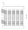
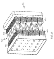
- Unitary heat exchangers 604 ( FIGS. 6A and 6B ), 704 ( FIG. 7 ), and 804 ( FIG. 8 ) are identical to unitary heat exchanger 204 of FIG. 4A (the outer wall of the inlet plenum 610 and the slip joint of the integral bellows portion are not shown in FIGS. 6A and 6B (the outer wall of the inlet plenum 610 has been omitted for ease of illustration to show inner wall 617 and tube inlets 615), FIG. 7 , and FIG.
- the plurality of heat transfer fins 650 of the relatively straight integrally-formed compliant heat exchanger tubes 602 of unitary heat exchanger 604 are substantially square or rectangular and oriented as exit louvers to direct flow; ii) the plurality of heat transfer fins 750 of the relatively straight integrally-formed compliant heat exchanger tubes 702 of unitary heat exchanger 704 ( FIG.7 ) are substantially square or rectangular with edges that contact the heat transfer fins of an adjacent integrally-formed compliant heat transfer tube; and iii) the plurality of heat transfer fins 850 of the relatively straight integrally-formed compliant heat exchanger tubes 802 of unitary heat exchanger 804 ( FIG.
- each of the unitary heat exchangers 204, 604, 704, and 804 may be closely packed making the resulting unitary heat exchanger more compact relative to conventional heat exchangers and to unitary heat exchangers 904 and 1004 as hereinafter described.
- a unitary heat exchanger 904 is identical to the unitary heat exchanger of FIG. 4A , except that the plurality of integrally-formed compliant heat exchanger tubes 902 comprise curved tubular members and there is no integral bellows portion.
- the plurality of integrally-formed compliant heat exchanger tubes 902 extend between and are integral with inlet and outlet plenums 910 and 912.
- the outer wall of the inlet plenum 910 has been omitted in FIG. 9 for ease of illustration.
- a plurality of tube inlets 915 are provided in the inner wall 917 of the inlet plenum 910. While only two tube inlets 915 are depicted in FIG.
- each integrally-formed compliant heat exchanger tube is associated with a tube inlet 915 (and a tube outlet (not shown).
- unitary heat exchanger 904 may include a lesser or greater number of integrally-formed compliant heat exchanger tubes than are shown in FIG. 9 .
- the integrally-formed compliant heat exchanger tubes 902 may be curved, for example, in either the tangential or radial directions, or may be curved in both the tangential and radial directions to provide optimal compliance and thereby increase thermo-mechanical fatigue strength.
- the integrally-formed compliant heat exchanger tubes 902 may be configured as substantially S-shaped heat exchanger tubes.
- Each substantially S-shaped heat exchanger tube includes a substantially transversely extending curved central portion and curved proximal and distal tube end portions, the curved proximal and distal tube end portions extending outwardly away from the transversely extending curved central portion.
- the plurality of integral heat transfer fins 950 in unitary heat exchanger 904 are arranged in one or more fin groups.
- the plurality of integral heat transfer fins 950 are arranged in a first fin group 952 proximate the proximal tube end, a second fin group 954 proximate the distal tube end, and a third fin group 956.
- the plurality of heat transfer fins 950 extend radially outwardly along at least a portion of the tubular member in the same manner, as described above.As noted previously, the positioning (locations) and number of fins and fin group(s) may vary.
- the plurality of integrally-formed compliant heat exchanger tubes 902 and heat transfer fins 950 are configured to achieve minimum cross sectional area and pressure drop with respect to the cooling flow direction. Heat transfer fins may be omitted in areas where the tube 902 bends to minimize stress concentrations and to maximize compliance throughout the unitary heat exchanger. While heat exchanger tube 902 does not include an integral bellows portion, it is to be understood that one or more integral bellows portions may be included in the one or more tubes 902 of unitary heat exchanger 904. As noted previously, the integral bellows portion comprises a bellows ( FIG. 13 ) and may further comprise a slip joint ( FIG. 4C ).
- FIG. 10 depicts another exemplary unitary heat exchanger 1004 having an alternative curved configuration for the plurality of integrally-formed compliant heat exchanger tubes.
- the unitary heat exchanger 1004 is identical to the unitary heat exchanger of FIG. 4A , except that the plurality of integrally-formed compliant heat exchanger tubes 1002 comprise curved tubular members in which adjacent curved integrally-formed compliant heat exchanger tubes together form an "X" shape as viewed isometrically ( FIG. 10 ), a proximal tube end 1007 is offset from a distal tube end 1009 of each integrally-formed compliant heat exchanger tube 1002, and there is no integral bellows portion.
- the heat transfer fins 1050 of the third fin group (the third fin group in FIG.
- the plurality of integrally-formed compliant heat exchanger tubes 1002 and heat transfer fins 1050 in unitary heat exchanger 1004 are configured to achieve minimum cross sectional area and pressure drop with respect to the cooling flow direction 1022. Heat transfer fins may be omitted in areas where the tube 1002 bends to minimize stress concentrations and to maximize compliance throughout the unitary heat exchanger structure.
- the plurality of integrally-formed compliant heat exchanger tubes 1002 extend between and are integral with inlet and outlet plenums 1010 and 1012.
- the outer wall of the inlet plenum 1010 has been omitted in FIG. 10 for ease of illustration.
- a plurality of tube inlets 1015 are provided in the inner wall 1017 of the inlet plenum 1010. While only six tube inlets 1015 are depicted in FIG. 10 for ease of illustration, it is to be understood that each integrally-formed compliant heat exchanger tube is associated with a tube inlet 1015 (and a tube outlet (not shown)).
- unitary heat exchanger 1004 may include a lesser or greater number of integrally-formed compliant heat exchanger tubes, fins, and fin groups than are shown in FIG. 10 .
- heat exchanger tube 1002 does not include an integral bellows portion as previously described, it is to be understood that one or more integral bellows portions may be included in the one or more tubes 1002 of unitary heat exchanger 1004.
- the integral bellows portion comprises a bellows ( FIG. 13 ) and may further comprise a slip joint ( FIG. 4C ).
- integrally-formed compliant heat transfer tubes have been described with particular curved configurations, it is to be understood that curved integrally-formed compliant heat transfer tubes may be curved in other manners to provide compliance for enhancing thermo-mechanical fatigue strength.
- unitary heat exchangers having relatively straight integrally-formed compliant heat exchanger tubes or curved integrally-formed compliant heat exchanger tubes have been described, it is to be understood that according to exemplary embodiments, a single unitary heat exchanger may include both relatively straight and curved integrally-formed compliant heat exchanger tubes.
- a single unitary heat exchanger may include combinations of heat exchanger tubes 402, 602, 702, 802, 902, 1002, and variations thereof.
- the relatively straight and the curved integrally-formed compliant heat exchanger tubes may be fabricated with internal heat transfer augmentation features such as spiral grooves or turbulators, dimples, spherical bumps, and other internal augmenting devices as are known to those having ordinary skill in the art.
- internal heat transfer augmentation features such as spiral grooves or turbulators, dimples, spherical bumps, and other internal augmenting devices as are known to those having ordinary skill in the art.
- the external wall surfaces of the integrally-formed compliant heat exchanger tubes may be enhanced with oval or airfoil shapes to reduce pressure losses in the tube bundle while simultaneously enhancing external surface area.
- External heat transfer augmentation features may be employed such as dimples or rougheners to speed transition to turbulent flow and to augment heat transfer in the tubular bundle.
- integrally-formed compliant heat exchanger tubes e.g., tubes 402, 602, 702, 802 and tubes 902 and 1002 (inclusive of the integral bellows portion)
- the integrally-formed compliant heat exchanger tubes may be separately available, in which case they can be brazed or otherwise coupled to an inlet plenum, an outlet plenum, or both to form a multi-piece heat exchanger (or simply a "heat exchanger" as used herein).
- the unitary heat exchangers in accordance with the present invention can be embodied in a variety of forms for use in gas turbine engines and in other applications.
- the previously described cooling air heat exchanger is merely one embodiment.
- the unitary heat exchangers of the present invention can be implemented as recuperators for heating compressed air prior to the entry thereof in the combustor.
- FIG. 11 a simplified cross section view of a portion of another exemplary gas turbine engine 1110 is depicted. In this exemplary engine design, cold air flows from compressor 1111 along a first flow path 1122 and into recuperator 1114.
- the cold compressed air may be heated by the flow of hot exhaust gas from combustor 1112, positioned within combustor case 1113, by way of exhaust gas flow path 1126.
- the heated compressed air can then flow along the second flow path 1124 and into combustor 1112.
- the heated compressed air may then be used in the combustion process in combustor 1112 to produce exhaust gas which can be cycled through recuperator 1114 along exhaust flow path 1126.
- Recuperator 1114 beneficially includes the features as described above with regard to cooling air unitary heat exchanger. These features may include one or more of structurally compliant, counter-sunk inlets, varying wall thickness features, curved or contoured inlets, and external or internal heat transfer augmentation features. However, the recuperator 1114 may be sized and shaped to accommodate its functionality as a recuperator. Generally speaking, the length of tubes may be modified, the number of tubes may be modified, the inside and outside diameters and wall thickness of the tubes may be modified, the shape of the overall unitary heat exchanger may be modified, and the flow configuration may be modified, among other things, to conform to the application.
- Additive manufacturing techniques include, for example, direct metal laser sintering (DMLS - a form of direct metal laser fusion (DMLF)) with nickel base super-alloys, low density titanium, and aluminum alloys. DMLS is discussed in greater detail below.
- DMLS direct metal laser sintering
- Another technique includes electron beam melting (EBM) with titanium, titanium aluminide, and nickel base super-alloy materials.
- EBM electron beam melting
- MIM metal injection molding
- the unitary heat exchangers such as the cooling air heat exchangers 204, 604, 704, 804, 904, and 1004 or the recuperator 1114 as shown in FIG. 11 , may be manufactured using additive manufacturing techniques.
- the integrally-formed compliant heat exchanger tubes may be manufactured using additive manufacturing techniques.
- Additive manufacturing techniques may begin with providing a model, such as a design model, of the heat exchange system.
- the model may be defined in any suitable manner.
- the model may be designed with computer aided design (CAD) software and may include three-dimensional ("3D") numeric coordinates of the entire configuration of the heat exchange system including both external and internal surfaces.
- the model may include a number of successive two-dimensional ("2D") cross-sectional slices that together form the 3D component.
- the unitary heat exchanger is formed according to the model, using a rapid prototyping or additive layer manufacturing process.
- additive layer manufacturing processes include: micro-pen deposition in which liquid media is dispensed with precision at the pen tip and then cured; selective laser sintering in which a laser is used to sinter a powder media in precisely controlled locations; laser wire deposition in which a wire feedstock is melted by a laser and then deposited and solidified in precise locations to build the product; electron beam melting; laser engineered net shaping; and direct metal deposition.
- additive manufacturing techniques provide flexibility in free-form fabrication with few or no geometric constraints, fast material processing time, and innovative joining techniques.
- direct metal laser fusion may be used to produce the heat exchange system.
- DMLF is a commercially available laser-based rapid prototyping and tooling process by which complex parts may be directly produced by precision melting and solidification of metal powder into successive layers of larger structures, each layer corresponding to a cross-sectional layer of the 3D component.
- DMLF may include direct metal laser sintering (DMLS), as previously noted.
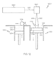
- FIG. 12 is a schematic view of an exemplary DMLF system 1200 for manufacturing the heat exchange system, for example cooling air unitary heat exchangers 204, 604, 704, 804, 904, or 1004 or the recuperator 1114 as shown in FIG. 11 , in accordance with an exemplary embodiment.
- the system 1200 includes a fabrication device 1210, a powder delivery device 1230, a scanner 1240, and a laser 1260 that function to manufacture the article 1250 (e.g., the heat exchange system) with build material 1270.
- the fabrication device 1210 includes a build container 1212 with a fabrication support 1214 on which the article 1250 is formed and supported.
- the fabrication support 1214 is movable within the build container 1212 in a vertical direction and is adjusted in such a way to define a working plane 1216.
- the delivery device 1230 includes a powder chamber 1232 with a delivery support 1234 that supports the build material 1270 and is also movable in the vertical direction.
- the delivery device 1230 further includes a roller or wiper 1236 that transfers build material 1270 from the delivery device 1230 to the fabrication device 1210.
- a base block 1244 may be installed on the fabrication support 1214.
- the fabrication support 1214 is lowered and the delivery support 1234 is raised.
- the roller or wiper 1236 scrapes or otherwise pushes a portion of the build material 1270 from the delivery device 1230 to form the working plane 1216 in the fabrication device 1210.
- the laser 1260 emits a laser beam 1262, which is directed by the scanner 1240 onto the build material 1270 in the working plane 1216 to selectively fuse the build material 1270 into a cross-sectional layer of the article 1250 according to the design.
- the speed, position, and other operating parameters of the laser beam 1262 are controlled to selectively fuse the powder of the build material 1270 into larger structures by rapidly melting the powder particles that may melt or diffuse into the solid structure below, and subsequently, cool and re-solidify.
- each layer of build material 1270 may include unfused and fused build material 1270 that respectively corresponds to the cross-sectional passages and walls that form the article 1250.
- the laser beam 1262 is relatively low power to selectively fuse the individual layer of build material 1270.
- the laser beam 1262 may have a power of approximately 50 to 500 Watts, although any suitable power may be provided.
- the fabrication support 1214 Upon completion of each layer, the fabrication support 1214 is lowered and the delivery support 1234 is raised. Typically, the fabrication support 1214, and thus the article 1250, does not move in a horizontal plane during this step.
- the roller or wiper 1236 again pushes a portion of the build material 1270 from the delivery device 1230 to form an additional layer of build material 1270 on the working plane 1216 of the fabrication device 1210.
- the laser beam 1262 is movably supported relative to the article 1250 and is again controlled to selectively form another cross-sectional layer. As such, the article 1250 is positioned in a bed of build material 1270 as the successive layers are formed such that the unfused and fused material supports subsequent layers.
- Unfused build material powder as a result of forming the internal slip joint may be removed from the completed unitary heat exchanger through removal holes in the inner wall surface of the tubular member in encircled region A (see, e.g., FIG. 4C )
- the delivery of build material 1270 and movement of the article 1250 in the vertical direction are relatively constant and only the movement of the laser beam 1262 is selectively controlled to provide a simpler and more precise implementation.
- the localized fusing of the build material 1270 enables more precise placement of fused material to reduce or eliminate the occurrence of over-deposition of material and excessive energy or heat, which may otherwise result in cracking or distortion.
- the unused and unfused build material 1270 may be reused, thereby further reducing scrap.
- the build material 1270 may be formed by any suitable powder, including powdered metals, such as a stainless steel powder, and alloys and super alloy materials, such as nickel-based or cobalt superalloys.
- the build material 1270 is a high temperature nickel base super alloy such as IN718.
- MAR-M-247, IN738, titanium, aluminum, titanium-aluminide, or other suitable alloys may be employed.
- the powder build material 1270 may be selected for enhanced strength, durability, and useful life, particularly at high temperatures, although as described below, the powder build material 1270 may also be selected based on the intended function of the area being formed.
- the complete heat exchange system may undergo finishing treatments. Finishing treatments may include, for example, aging, annealing, quenching, peening, polishing, hot isostatic pressing (HIP), or coatings.
- HIP hot isostatic pressing
- an encapsulation layer is applied to the article and pressure and heat are applied to remove or reduce any porosity and cracks internal to or on the surface of the component, as described in United States Patent Application Serial No. 12/820,652, titled “METHODS FOR MANUFACTURING TURBINE COMPONENTS,” filed June 22, 2010, and published as United States Patent Application Publication No.
- the encapsulation layer functions to effectively convert any surface porosity and cracks into internal porosity and cracks, and after the application of pressure and heat, removes or reduces the porosity and cracks. Such encapsulation layers may be subsequently removed or maintained to function as an oxidation protection layer.
- the encapsulation layer may be a metal or alloy that is compatible with the substrate and may be applied by a plating or coating process, as described below.
- the HIP process may be performed at a processing temperature in a range of about 1000° C to about 1300° C and may be performed at a pressure in a range of about 1 ksi to about 25 ksi for a time period of about 1 to about 10 hours.
- the HIP processing temperature, pressure, and time may be smaller or larger to form a compacted solid having negligible porosity.
- the heat exchange system may be machined to final specifications.
- the heat exchange system as referred to herein regarding additive manufacturing techniques corresponds with the finished heat exchange system shown in the figures.
- the heat exchange system/unitary heat exchanger may be tested and installed in a gas turbine engine, as shown in FIGS. 2 and 11 .
- a single heat exchange system may be manufactured simultaneously on a common base block (e.g., base block 1244) to provide a common orientation and a known point of reference and formed as discussed above.
- Successive layers can be formed for the group of articles simultaneously according to a common module or design.
- the powdered metal may be deposited across a single working plane and one or more lasers may selectively fuse the layers of each heat exchange system, either sequentially or simultaneously.
- the articles may then be lowered together for the formation of the next layer. Simultaneous fabrication of a number of heat exchange systems may reduce cost and variability of the manufacturing process.
- unitary heat exchangers having integrally-formed compliant heat exchanger tubes and heat exchange systems including the same have been provided.
- durability and life span of the heat exchange system may be improved by manufacturing each portion of the heat exchange system using designs that minimize the structural stresses that will be encountered during operation.
- rapid prototyping and additive manufacturing techniques, including DMLF/DMLS reduces cracks and other issues and reduces costs and cycle time in the system design, particularly in the iterative environment of gas turbine engine component design.
- the heat exchangers and heat exchange systems have improved efficiency, reduced manufacturing costs, and increased operating lifespan over conventional heat exchangers, with less fluidic loss for improved engine cycle performance, and less weight.
Landscapes
- Engineering & Computer Science (AREA)
- Physics & Mathematics (AREA)
- General Engineering & Computer Science (AREA)
- Mechanical Engineering (AREA)
- Thermal Sciences (AREA)
- Geometry (AREA)
- Heat-Exchange Devices With Radiators And Conduit Assemblies (AREA)
Applications Claiming Priority (2)
| Application Number | Priority Date | Filing Date | Title |
|---|---|---|---|
| US13/911,904 US9752835B2 (en) | 2013-06-06 | 2013-06-06 | Unitary heat exchangers having integrally-formed compliant heat exchanger tubes and heat exchange systems including the same |
| EP14168912.5 | 2014-05-19 |
Related Parent Applications (1)
| Application Number | Title | Priority Date | Filing Date |
|---|---|---|---|
| EP14168912.5 Division | 2013-06-06 | 2014-05-19 |
Publications (2)
| Publication Number | Publication Date |
|---|---|
| EP2811249A1 true EP2811249A1 (de) | 2014-12-10 |
| EP2811249B1 EP2811249B1 (de) | 2018-11-14 |
Family
ID=50732018
Family Applications (1)
| Application Number | Title | Priority Date | Filing Date |
|---|---|---|---|
| EP14176161.9A Active EP2811249B1 (de) | 2013-06-06 | 2014-05-19 | Einheitliche Wärmetauscher mit einstückigen nachgiebigen Wärmetauscherrohren und Wärmetauschersysteme damit |
Country Status (2)
| Country | Link |
|---|---|
| US (1) | US9752835B2 (de) |
| EP (1) | EP2811249B1 (de) |
Cited By (19)
| Publication number | Priority date | Publication date | Assignee | Title |
|---|---|---|---|---|
| EP3054256A1 (de) * | 2015-02-06 | 2016-08-10 | United Technologies Corporation | Additiv gefertigtes rohrwärmetauschersystem mit additiv gefertigter verkleidung |
| WO2016139019A1 (de) * | 2015-03-05 | 2016-09-09 | Mahle International Gmbh | Wärmetauscher, insbesondere für ein kraftfahrzeug |
| EP3130781A1 (de) * | 2015-08-14 | 2017-02-15 | United Technologies Corporation | Wärmetauscher für gekühlte kühlluft |
| GB2542490A (en) * | 2015-08-11 | 2017-03-22 | Hamilton Sundstrand Corp | Heat exchanger and fabrication |
| US9777963B2 (en) | 2014-06-30 | 2017-10-03 | General Electric Company | Method and system for radial tubular heat exchangers |
| GB2549069A (en) * | 2016-03-23 | 2017-10-11 | Hieta Tech Ltd | Multifunctional structure of an additively manufactured article |
| US20170292195A1 (en) | 2016-04-12 | 2017-10-12 | United Technologies Corporation | Light weight component with internal reinforcement and method of making |
| EP3231599A1 (de) * | 2016-04-12 | 2017-10-18 | United Technologies Corporation | Leichtgewichtiges gehäuse für innere komponente mit integrierten wärmeverwaltungsfunktionen und verfahren zur herstellung |
| EP3242105A1 (de) * | 2016-05-06 | 2017-11-08 | United Technologies Corporation | Wärmetauscher mit wärmetemperaturgradienten |
| US9835380B2 (en) | 2015-03-13 | 2017-12-05 | General Electric Company | Tube in cross-flow conduit heat exchanger |
| US10006369B2 (en) | 2014-06-30 | 2018-06-26 | General Electric Company | Method and system for radial tubular duct heat exchangers |
| US10302017B2 (en) | 2016-04-12 | 2019-05-28 | United Technologies Corporation | Light weight component with acoustic attenuation and method of making |
| US10323325B2 (en) | 2016-04-12 | 2019-06-18 | United Technologies Corporation | Light weight housing for internal component and method of making |
| US10335850B2 (en) | 2016-04-12 | 2019-07-02 | United Technologies Corporation | Light weight housing for internal component and method of making |
| US10378835B2 (en) | 2016-03-25 | 2019-08-13 | Unison Industries, Llc | Heat exchanger with non-orthogonal perforations |
| US10724131B2 (en) | 2016-04-12 | 2020-07-28 | United Technologies Corporation | Light weight component and method of making |
| US10821509B2 (en) | 2016-01-20 | 2020-11-03 | General Electric Company | Additive heat exchanger mixing chambers |
| EP3514469B1 (de) | 2018-01-23 | 2021-05-05 | Hamilton Sundstrand Corporation | Wärmetauscher mit flexiblem verteiler |
| DE102020003270A1 (de) | 2020-06-01 | 2021-12-02 | Helmut Mainka | Ausgleichselement für den Längenausgleich von Verbindungsmuffen für flüssigkeits- oder gasführende Leitungen |
Families Citing this family (43)
| Publication number | Priority date | Publication date | Assignee | Title |
|---|---|---|---|---|
| WO2015053941A1 (en) * | 2013-10-07 | 2015-04-16 | United Technologies Corporation | Article with internal structure |
| US20150352661A1 (en) * | 2014-06-04 | 2015-12-10 | Hamilton Sundstrand Corporation | Ultrasonic additive manufacturing assembly and method |
| US10809016B2 (en) * | 2015-02-06 | 2020-10-20 | Raytheon Technologies Corporation | Heat exchanger system with additively manufactured heat transfer tube that follows a non-linear path |
| US10907500B2 (en) * | 2015-02-06 | 2021-02-02 | Raytheon Technologies Corporation | Heat exchanger system with spatially varied additively manufactured heat transfer surfaces |
| US20160231065A1 (en) * | 2015-02-09 | 2016-08-11 | United Technologies Corporation | Heat exchanger article with hollow tube having plurality of vanes |
| FR3032783B1 (fr) * | 2015-02-12 | 2017-03-10 | Air Liquide | Echangeur-reacteur milli-structure pour une production d'hydrogene inferieure a 10 nm3/h |
| US10018424B2 (en) | 2016-02-05 | 2018-07-10 | Hamilton Sundstrand Corporation | Counter spiral tube and shell heat exchanger |
| US10753229B2 (en) * | 2016-02-17 | 2020-08-25 | Pratt & Whitney Canada Corp | Mounting arrangement for mounting a fluid cooler to a gas turbine engine case |
| US10443958B2 (en) * | 2016-04-25 | 2019-10-15 | Raytheon Company | Powdered metal as a sacrificial material for ultrasonic additive manufacturing |
| US10253785B2 (en) * | 2016-08-31 | 2019-04-09 | Unison Industries, Llc | Engine heat exchanger and method of forming |
| US20180057942A1 (en) * | 2016-08-31 | 2018-03-01 | Unison Industries, Llc | Methods for manufacturing a heat exchanger |
| SG11201901764RA (en) * | 2016-09-01 | 2019-03-28 | Additive Rocket Corp | Structural heat exchanger |
| US10247296B2 (en) | 2016-12-12 | 2019-04-02 | General Electric Company | Additively manufactured gearbox with integral heat exchanger |
| US20180244127A1 (en) * | 2017-02-28 | 2018-08-30 | General Electric Company | Thermal management system and method |
| US10175003B2 (en) | 2017-02-28 | 2019-01-08 | General Electric Company | Additively manufactured heat exchanger |
| US10184728B2 (en) * | 2017-02-28 | 2019-01-22 | General Electric Company | Additively manufactured heat exchanger including flow turbulators defining internal fluid passageways |
| EP3382235B1 (de) | 2017-03-31 | 2021-03-17 | HS Marston Aerospace Limited | Komponente mit wärmetauscher |
| US10821521B2 (en) | 2017-04-11 | 2020-11-03 | Hamilton Sunstrand Corporation | Article surface finishing method |
| EP3413001B1 (de) | 2017-06-06 | 2020-01-08 | Ge Avio S.r.l. | Generativ hergestellter wärmetauscher |
| US10157814B1 (en) | 2017-06-27 | 2018-12-18 | International Business Machines Corporation | Compliant heat sink |
| US10780632B2 (en) * | 2017-06-28 | 2020-09-22 | Evapco, Inc. | Additive manufactured header for heat exchangers |
| EP3645196B1 (de) * | 2017-06-28 | 2025-12-10 | Evapco, Inc. | Mittels generativer fertigung hergestellte endkammer für wärmetauscher |
| AU2018267568A1 (en) * | 2017-11-22 | 2019-09-12 | Transportation Ip Holdings, Llc | Thermal management system and method |
| US12447793B2 (en) * | 2017-11-22 | 2025-10-21 | Transportation Ip Holdings, Llc | Shell and tube heat exchanger with flexible diaphragm |
| JP2019138553A (ja) * | 2018-02-09 | 2019-08-22 | 三桜工業株式会社 | 熱交換器、egrクーラー及び熱交換器製造方法 |
| US12228349B2 (en) * | 2018-02-20 | 2025-02-18 | K&N Engineering, Inc. | Modular intercooler block |
| US10962293B2 (en) | 2018-02-23 | 2021-03-30 | Unison Industries, Llc | Heat exchanger assembly |
| US11333447B2 (en) * | 2018-03-27 | 2022-05-17 | Hamilton Sundstrand Corporation | Additively manufactured heat exchangers and methods for making the same |
| US11035626B2 (en) | 2018-09-10 | 2021-06-15 | Hamilton Sunstrand Corporation | Heat exchanger with enhanced end sheet heat transfer |
| JP7357207B2 (ja) * | 2019-11-26 | 2023-10-06 | 株式会社ノーリツ | 熱交換器およびこれを備えた温水装置 |
| US11709021B2 (en) | 2020-07-13 | 2023-07-25 | Transportation Ip Holdings, Llc | Thermal management system and method |
| US11802734B2 (en) * | 2020-09-03 | 2023-10-31 | Transportation Ip Holdings, Llc | Thermal management system and method |
| US11371786B2 (en) * | 2020-10-21 | 2022-06-28 | General Electric Company | Heat exchanger for a gas turbine engine |
| DE102022106477A1 (de) * | 2021-04-20 | 2022-10-20 | Transportation Ip Holdings, Llc | Übertragungsvorrichtung |
| EP4306786B1 (de) * | 2022-07-15 | 2025-10-15 | RTX Corporation | Wärmetauscher für flugzeuge |
| US12379108B2 (en) | 2023-01-06 | 2025-08-05 | Ge Vernova Infrastructure Technology Llc | Method of operating gas turbine combustor with multiple fuel stages |
| US20240230090A1 (en) | 2023-01-06 | 2024-07-11 | Ge Infrastructure Technology Llc | Combustor head end section with air supply system for bundled tube fuel nozzle contained therein |
| US12259194B2 (en) | 2023-07-10 | 2025-03-25 | General Electric Company | Thermal management system |
| US20250020080A1 (en) * | 2023-07-14 | 2025-01-16 | Raytheon Technologies Corporation | Bead protrusions heat transfer surface structure of fluid conduits and manifolds |
| US12631143B2 (en) | 2024-03-28 | 2026-05-19 | General Electric Company | Gas turbine engine with heat exchanger assembly |
| US12631407B2 (en) | 2024-04-26 | 2026-05-19 | Rolls-Royce North American Technologies Inc. | Heat exchanger with expansion joint for thermal expansion and external force tolerance |
| US12504240B2 (en) | 2024-04-26 | 2025-12-23 | Rolls-Royce North American Technologies Inc. | Heat exchanger with expansion joint insert for thermal expansion and external force tolerance |
| US12704092B2 (en) | 2024-06-18 | 2026-08-11 | General Electric Company | Gas turbine engine with heat exchanger |
Citations (5)
| Publication number | Priority date | Publication date | Assignee | Title |
|---|---|---|---|---|
| US3185210A (en) * | 1962-05-23 | 1965-05-25 | American Schack Company Inc | High temperature recuperator |
| FR2311269A1 (fr) * | 1975-05-16 | 1976-12-10 | Remeha Fabrieken Bv | Echangeur thermique en metal moule et moule pour sa fabrication |
| US7124572B2 (en) | 2004-09-14 | 2006-10-24 | Honeywell International, Inc. | Recuperator and turbine support adapter for recuperated gas turbine engines |
| EP1978323A2 (de) * | 2007-04-05 | 2008-10-08 | Honeywell International Inc. | Wärmetauscher mit ausziehbarer Dehnungsfuge |
| US20110311389A1 (en) | 2010-06-22 | 2011-12-22 | Honeywell International Inc. | Methods for manufacturing turbine components |
Family Cites Families (50)
| Publication number | Priority date | Publication date | Assignee | Title |
|---|---|---|---|---|
| US1882085A (en) * | 1931-04-04 | 1932-10-11 | Herman Nelson Corp | Radiator |
| US2241209A (en) * | 1940-06-08 | 1941-05-06 | Edward S Lea | Finned condenser tube |
| US2911200A (en) | 1957-03-28 | 1959-11-03 | Griscom Russell Co | Heat exchanger tube sheet joint construction |
| US3364548A (en) * | 1964-12-08 | 1968-01-23 | Alex A. Marco | Method for producing an electroformed heat exchanger |
| US3409075A (en) * | 1965-08-20 | 1968-11-05 | Union Carbide Corp | Matrix heat exchange cores |
| CH476273A (de) | 1968-03-28 | 1969-07-31 | Metallgesellschaft Ag | Vorrichtung zum Eindampfen von Flüssigkeiten |
| US3527291A (en) * | 1968-05-16 | 1970-09-08 | Aero Flow Dynamics Inc | Expansion accommodating means and method |
| US3549176A (en) * | 1968-10-29 | 1970-12-22 | Aeroquip Corp | Flexible flow liner for bellows joints |
| CH535415A (de) | 1972-08-31 | 1973-03-31 | Beth Gmbh Maschf | Gaskühler |
| FR2334076A1 (fr) | 1975-12-05 | 1977-07-01 | Sera Husson Etu Realisa Aerody | Echangeur thermique air-air ou air-eau a longue duree de service et a rendement constant, construit a partir d'elements modulaires |
| US4350372A (en) * | 1980-01-21 | 1982-09-21 | Logsdon Duane D | Expansion coupling for large diameter plastic pipes |
| US4858686A (en) | 1983-10-19 | 1989-08-22 | The Allen Group, Inc. | Heat exchanger |
| GB2173890B (en) | 1985-04-20 | 1988-11-09 | Aisin Seiki | Heat exchangers |
| US4832114A (en) | 1987-12-02 | 1989-05-23 | Yeh Hsu Chieh | Device for producing high heat transfer in heat exchanger tubes |
| US5145215A (en) * | 1991-04-26 | 1992-09-08 | Senior Engineering Investments, B.V. | Flexible coupler apparatus |
| US5305616A (en) | 1992-03-23 | 1994-04-26 | General Electric Company | Gas turbine engine cooling system |
| US5407237A (en) * | 1993-02-26 | 1995-04-18 | The United States Of America As Represented By The Secretary Of The Air Force | Flexible coupling |
| JPH0755386A (ja) | 1993-08-18 | 1995-03-03 | Sanden Corp | 熱交換器 |
| SE513642C2 (sv) * | 1996-03-29 | 2000-10-16 | Valeo Engine Cooling Ab | Värmeväxlare samt sätt vid framställning av en dylik |
| US6032463A (en) * | 1998-07-22 | 2000-03-07 | Caterpillar Inc | Exhaust connector assembly and kit for a segmented exhaust manifold |
| JP2002130060A (ja) | 2000-10-24 | 2002-05-09 | Katayama Kogyo Co Ltd | Egrガス冷却装置 |
| GB2422004A (en) * | 2005-01-07 | 2006-07-12 | Hiflux Ltd | Plate heat exchanger |
| RU2282121C1 (ru) | 2005-02-09 | 2006-08-20 | Открытое Акционерное Общество "Научно-Исследовательский И Проектный Институт Карбамида И Продуктов Органического Синтеза" (Оао Ниик) | Вертикальный пленочный теплообменник |
| US7871578B2 (en) | 2005-05-02 | 2011-01-18 | United Technologies Corporation | Micro heat exchanger with thermally conductive porous network |
| GB0511460D0 (en) | 2005-06-06 | 2005-07-13 | Univ Liverpool | Process |
| US8511111B2 (en) | 2005-06-10 | 2013-08-20 | Michael A. Lambert | Automotive adsorption heat pump |
| DE102006003317B4 (de) | 2006-01-23 | 2008-10-02 | Alstom Technology Ltd. | Rohrbündel-Wärmetauscher |
| AP2008004678A0 (en) | 2006-05-05 | 2008-12-31 | Plascoenergy Ip Holdings | A control system for the conversion of a carbonaceous feedstock into gas |
| US7398798B2 (en) * | 2006-06-22 | 2008-07-15 | Gm Global Technology Operations, Inc. | Flexible sleeve liner for a convolute duct |
| US7810552B2 (en) | 2006-12-20 | 2010-10-12 | The Boeing Company | Method of making a heat exchanger |
| US7866372B2 (en) | 2006-12-20 | 2011-01-11 | The Boeing Company | Method of making a heat exchanger core component |
| DE102007027639A1 (de) | 2007-06-15 | 2008-12-18 | Rolls-Royce Deutschland Ltd & Co Kg | Wärmetauscher für eine Fluggasturbine |
| GB0720627D0 (en) | 2007-10-19 | 2007-11-28 | Applied Cooling Technology Ltd | Turbulator for heat exchanger tube and method of manufacture |
| WO2009105454A2 (en) | 2008-02-22 | 2009-08-27 | Liebert Corporation | Laminated sheet manifold for microchannel heat exchanger |
| US20100018673A1 (en) | 2008-07-22 | 2010-01-28 | Tai-Her Yang | Enclosure type inter-piping fluid thermal energy transfer device |
| DE102008034819A1 (de) | 2008-07-23 | 2010-01-28 | Smk Systeme Metall Kunststoff Gmbh & Co. Kg. | Abgaskühler |
| DE102009028487A1 (de) | 2008-08-12 | 2010-02-25 | Visteon Global Technologies, Inc., Van Buren Township | Vorrichtung zur Kühlung eines Gasstroms |
| DE102009040560A1 (de) * | 2009-09-08 | 2011-03-10 | Krones Ag | Röhrenwärmetauscher |
| US8307662B2 (en) | 2009-10-15 | 2012-11-13 | General Electric Company | Gas turbine engine temperature modulated cooling flow |
| AU2010306204B2 (en) | 2009-10-16 | 2015-09-17 | 3Shape A/S | Individually tailored soft components |
| US8499544B2 (en) | 2009-11-17 | 2013-08-06 | General Electric Company | Turbogenerator with cooling system |
| KR101608996B1 (ko) | 2010-01-11 | 2016-04-05 | 엘지전자 주식회사 | 열 교환기 |
| US8506242B2 (en) | 2010-05-04 | 2013-08-13 | Brayton Energy Canada, Inc. | Method of making a heat exchange component using wire mesh screens |
| KR101600296B1 (ko) | 2010-08-18 | 2016-03-07 | 한온시스템 주식회사 | 이중관식 열교환기 및 그 제조방법 |
| DE102010040261A1 (de) | 2010-09-03 | 2012-03-08 | Eos Gmbh Electro Optical Systems | Verfahren zum Herstellen eines dreidimensionalen Objekts mit einer internen Struktur |
| EP2653708A1 (de) | 2010-12-13 | 2013-10-23 | Mitsubishi Electric Corporation | Abgasumlaufventil |
| US20120292000A1 (en) | 2011-05-16 | 2012-11-22 | Johnson Controls Technology Company | Turbulators for heat exchanger tubes |
| US9243563B2 (en) | 2012-01-25 | 2016-01-26 | Honeywell International Inc. | Gas turbine engine in-board cooled cooling air system |
| US9267390B2 (en) | 2012-03-22 | 2016-02-23 | Honeywell International Inc. | Bi-metallic actuator for selectively controlling air flow between plena in a gas turbine engine |
| US20140110095A1 (en) | 2012-10-18 | 2014-04-24 | Yung-Yu Chang | Heat-dissipating apparatus |
-
2013
- 2013-06-06 US US13/911,904 patent/US9752835B2/en active Active
-
2014
- 2014-05-19 EP EP14176161.9A patent/EP2811249B1/de active Active
Patent Citations (5)
| Publication number | Priority date | Publication date | Assignee | Title |
|---|---|---|---|---|
| US3185210A (en) * | 1962-05-23 | 1965-05-25 | American Schack Company Inc | High temperature recuperator |
| FR2311269A1 (fr) * | 1975-05-16 | 1976-12-10 | Remeha Fabrieken Bv | Echangeur thermique en metal moule et moule pour sa fabrication |
| US7124572B2 (en) | 2004-09-14 | 2006-10-24 | Honeywell International, Inc. | Recuperator and turbine support adapter for recuperated gas turbine engines |
| EP1978323A2 (de) * | 2007-04-05 | 2008-10-08 | Honeywell International Inc. | Wärmetauscher mit ausziehbarer Dehnungsfuge |
| US20110311389A1 (en) | 2010-06-22 | 2011-12-22 | Honeywell International Inc. | Methods for manufacturing turbine components |
Cited By (28)
| Publication number | Priority date | Publication date | Assignee | Title |
|---|---|---|---|---|
| US9777963B2 (en) | 2014-06-30 | 2017-10-03 | General Electric Company | Method and system for radial tubular heat exchangers |
| US10006369B2 (en) | 2014-06-30 | 2018-06-26 | General Electric Company | Method and system for radial tubular duct heat exchangers |
| EP3054256A1 (de) * | 2015-02-06 | 2016-08-10 | United Technologies Corporation | Additiv gefertigtes rohrwärmetauschersystem mit additiv gefertigter verkleidung |
| US10830543B2 (en) | 2015-02-06 | 2020-11-10 | Raytheon Technologies Corporation | Additively manufactured ducted heat exchanger system with additively manufactured header |
| WO2016139019A1 (de) * | 2015-03-05 | 2016-09-09 | Mahle International Gmbh | Wärmetauscher, insbesondere für ein kraftfahrzeug |
| US9835380B2 (en) | 2015-03-13 | 2017-12-05 | General Electric Company | Tube in cross-flow conduit heat exchanger |
| GB2542490A (en) * | 2015-08-11 | 2017-03-22 | Hamilton Sundstrand Corp | Heat exchanger and fabrication |
| US9746257B2 (en) | 2015-08-11 | 2017-08-29 | Hamilton Sundstrand Corporation | Heat exchanger and fabrication |
| GB2542490B (en) * | 2015-08-11 | 2021-04-21 | Hamilton Sundstrand Corp | Heat exchanger and fabrication |
| US10323887B2 (en) | 2015-08-11 | 2019-06-18 | Hamilton Sundstrand Corporation | Heat exchanger and fabrication |
| US10060353B2 (en) | 2015-08-14 | 2018-08-28 | United Technologies Corporation | Heat exchanger for cooled cooling air |
| EP3130781A1 (de) * | 2015-08-14 | 2017-02-15 | United Technologies Corporation | Wärmetauscher für gekühlte kühlluft |
| US10821509B2 (en) | 2016-01-20 | 2020-11-03 | General Electric Company | Additive heat exchanger mixing chambers |
| GB2549069A (en) * | 2016-03-23 | 2017-10-11 | Hieta Tech Ltd | Multifunctional structure of an additively manufactured article |
| US10378835B2 (en) | 2016-03-25 | 2019-08-13 | Unison Industries, Llc | Heat exchanger with non-orthogonal perforations |
| US10302017B2 (en) | 2016-04-12 | 2019-05-28 | United Technologies Corporation | Light weight component with acoustic attenuation and method of making |
| US10323325B2 (en) | 2016-04-12 | 2019-06-18 | United Technologies Corporation | Light weight housing for internal component and method of making |
| US10335850B2 (en) | 2016-04-12 | 2019-07-02 | United Technologies Corporation | Light weight housing for internal component and method of making |
| US10399117B2 (en) | 2016-04-12 | 2019-09-03 | United Technologies Corporation | Method of making light weight component with internal metallic foam and polymer reinforcement |
| US10619949B2 (en) | 2016-04-12 | 2020-04-14 | United Technologies Corporation | Light weight housing for internal component with integrated thermal management features and method of making |
| US10724131B2 (en) | 2016-04-12 | 2020-07-28 | United Technologies Corporation | Light weight component and method of making |
| EP3231599A1 (de) * | 2016-04-12 | 2017-10-18 | United Technologies Corporation | Leichtgewichtiges gehäuse für innere komponente mit integrierten wärmeverwaltungsfunktionen und verfahren zur herstellung |
| US20170292195A1 (en) | 2016-04-12 | 2017-10-12 | United Technologies Corporation | Light weight component with internal reinforcement and method of making |
| US11040372B2 (en) | 2016-04-12 | 2021-06-22 | Raytheon Technologies Corporation | Light weight component with internal reinforcement |
| US10260422B2 (en) | 2016-05-06 | 2019-04-16 | United Technologies Corporation | Heat temperature gradient heat exchanger |
| EP3242105A1 (de) * | 2016-05-06 | 2017-11-08 | United Technologies Corporation | Wärmetauscher mit wärmetemperaturgradienten |
| EP3514469B1 (de) | 2018-01-23 | 2021-05-05 | Hamilton Sundstrand Corporation | Wärmetauscher mit flexiblem verteiler |
| DE102020003270A1 (de) | 2020-06-01 | 2021-12-02 | Helmut Mainka | Ausgleichselement für den Längenausgleich von Verbindungsmuffen für flüssigkeits- oder gasführende Leitungen |
Also Published As
| Publication number | Publication date |
|---|---|
| US9752835B2 (en) | 2017-09-05 |
| US20140360698A1 (en) | 2014-12-11 |
| EP2811249B1 (de) | 2018-11-14 |
Similar Documents
| Publication | Publication Date | Title |
|---|---|---|
| EP2811249B1 (de) | Einheitliche Wärmetauscher mit einstückigen nachgiebigen Wärmetauscherrohren und Wärmetauschersysteme damit | |
| EP2865981B1 (de) | Gegenstromwärmetauschersysteme | |
| EP2636982B1 (de) | Rohrförmige Wärmetauschersystem | |
| EP2708296B1 (de) | Verfahren zur Herstellung Turbinenstatorschaufelanordnungen mit generativer Herstellungsmethode | |
| EP3413001B1 (de) | Generativ hergestellter wärmetauscher | |
| US10782071B2 (en) | Tubular array heat exchanger | |
| EP3470721B1 (de) | Flexibles, wärmeisolierendes, doppelwandiges rohr mit bälgen und verfahren zu dessen herstellung | |
| CN110546363B (zh) | 包括限定内部流体通路的流湍流器的增材制造的热交换器 | |
| EP2905538B1 (de) | Gasturbinenbrennkammern mit Effusions- und Prallkühlung und Verfahren zur Herstellung davon | |
| US20180283795A1 (en) | Tubular Array Heat Exchanger | |
| JP6183976B2 (ja) | ガスタービンエンジン用熱交換器 | |
| US20190024988A1 (en) | Header assembly for a heat exchanger | |
| EP3663562B1 (de) | Wärmeverwaltungssystem für gasturbinenmotor mit geringem bypass | |
| EP3115670B1 (de) | Turbinenmotorkupplungen und verfahren zur herstellung von turbinenmotorkupplungen |
Legal Events
| Date | Code | Title | Description |
|---|---|---|---|
| PUAI | Public reference made under article 153(3) epc to a published international application that has entered the european phase |
Free format text: ORIGINAL CODE: 0009012 |
|
| 17P | Request for examination filed |
Effective date: 20140708 |
|
| AK | Designated contracting states |
Kind code of ref document: A1 Designated state(s): AL AT BE BG CH CY CZ DE DK EE ES FI FR GB GR HR HU IE IS IT LI LT LU LV MC MK MT NL NO PL PT RO RS SE SI SK SM TR |
|
| AX | Request for extension of the european patent |
Extension state: BA ME |
|
| RAP1 | Party data changed (applicant data changed or rights of an application transferred) |
Owner name: HONEYWELL INTERNATIONAL INC. |
|
| RIC1 | Information provided on ipc code assigned before grant |
Ipc: F28F 1/00 20060101ALI20170331BHEP Ipc: F28F 1/08 20060101ALI20170331BHEP Ipc: F28D 7/00 20060101ALI20170331BHEP Ipc: F28D 1/053 20060101AFI20170331BHEP Ipc: B22F 3/105 20060101ALI20170331BHEP Ipc: F28F 1/26 20060101ALN20170331BHEP Ipc: F28D 21/00 20060101ALN20170331BHEP Ipc: F28D 7/16 20060101ALI20170331BHEP |
|
| STAA | Information on the status of an ep patent application or granted ep patent |
Free format text: STATUS: EXAMINATION IS IN PROGRESS |
|
| RIC1 | Information provided on ipc code assigned before grant |
Ipc: B22F 3/105 20060101ALI20170502BHEP Ipc: F28D 21/00 20060101ALN20170502BHEP Ipc: F28F 1/08 20060101ALI20170502BHEP Ipc: F28D 7/00 20060101ALI20170502BHEP Ipc: F28D 7/16 20060101ALI20170502BHEP Ipc: F28D 1/053 20060101AFI20170502BHEP Ipc: F28F 1/26 20060101ALN20170502BHEP Ipc: F28F 1/00 20060101ALI20170502BHEP |
|
| 17Q | First examination report despatched |
Effective date: 20170510 |
|
| RIC1 | Information provided on ipc code assigned before grant |
Ipc: F28D 1/053 20060101AFI20180516BHEP Ipc: F28D 21/00 20060101ALN20180516BHEP Ipc: F28F 1/00 20060101ALI20180516BHEP Ipc: F28F 1/26 20060101ALN20180516BHEP Ipc: B22F 3/105 20060101ALI20180516BHEP Ipc: F28D 7/16 20060101ALI20180516BHEP Ipc: F28D 7/00 20060101ALI20180516BHEP Ipc: F28F 1/08 20060101ALI20180516BHEP |
|
| GRAP | Despatch of communication of intention to grant a patent |
Free format text: ORIGINAL CODE: EPIDOSNIGR1 |
|
| STAA | Information on the status of an ep patent application or granted ep patent |
Free format text: STATUS: GRANT OF PATENT IS INTENDED |
|
| RIC1 | Information provided on ipc code assigned before grant |
Ipc: F28D 1/053 20060101AFI20180604BHEP Ipc: F28F 1/08 20060101ALI20180604BHEP Ipc: F28F 1/26 20060101ALN20180604BHEP Ipc: F28F 1/00 20060101ALI20180604BHEP Ipc: B22F 3/105 20060101ALI20180604BHEP Ipc: F28D 7/16 20060101ALI20180604BHEP Ipc: F28D 7/00 20060101ALI20180604BHEP Ipc: F28D 21/00 20060101ALN20180604BHEP |
|
| INTG | Intention to grant announced |
Effective date: 20180622 |
|
| RIC1 | Information provided on ipc code assigned before grant |
Ipc: F28D 1/053 20060101AFI20180620BHEP Ipc: F28F 1/00 20060101ALI20180620BHEP Ipc: F28D 21/00 20060101ALN20180620BHEP Ipc: F28D 7/16 20060101ALI20180620BHEP Ipc: F28D 7/00 20060101ALI20180620BHEP Ipc: F28F 1/26 20060101ALN20180620BHEP Ipc: B22F 3/105 20060101ALI20180620BHEP Ipc: F28F 1/08 20060101ALI20180620BHEP |
|
| GRAS | Grant fee paid |
Free format text: ORIGINAL CODE: EPIDOSNIGR3 |
|
| GRAA | (expected) grant |
Free format text: ORIGINAL CODE: 0009210 |
|
| STAA | Information on the status of an ep patent application or granted ep patent |
Free format text: STATUS: THE PATENT HAS BEEN GRANTED |
|
| AK | Designated contracting states |
Kind code of ref document: B1 Designated state(s): AL AT BE BG CH CY CZ DE DK EE ES FI FR GB GR HR HU IE IS IT LI LT LU LV MC MK MT NL NO PL PT RO RS SE SI SK SM TR |
|
| REG | Reference to a national code |
Ref country code: CH Ref legal event code: EP Ref country code: AT Ref legal event code: REF Ref document number: 1065333 Country of ref document: AT Kind code of ref document: T Effective date: 20181115 |
|
| REG | Reference to a national code |
Ref country code: DE Ref legal event code: R096 Ref document number: 602014035894 Country of ref document: DE |
|
| REG | Reference to a national code |
Ref country code: IE Ref legal event code: FG4D |
|
| REG | Reference to a national code |
Ref country code: NL Ref legal event code: MP Effective date: 20181114 |
|
| REG | Reference to a national code |
Ref country code: LT Ref legal event code: MG4D |
|
| REG | Reference to a national code |
Ref country code: AT Ref legal event code: MK05 Ref document number: 1065333 Country of ref document: AT Kind code of ref document: T Effective date: 20181114 |
|
| PG25 | Lapsed in a contracting state [announced via postgrant information from national office to epo] |
Ref country code: HR Free format text: LAPSE BECAUSE OF FAILURE TO SUBMIT A TRANSLATION OF THE DESCRIPTION OR TO PAY THE FEE WITHIN THE PRESCRIBED TIME-LIMIT Effective date: 20181114 Ref country code: NO Free format text: LAPSE BECAUSE OF FAILURE TO SUBMIT A TRANSLATION OF THE DESCRIPTION OR TO PAY THE FEE WITHIN THE PRESCRIBED TIME-LIMIT Effective date: 20190214 Ref country code: LT Free format text: LAPSE BECAUSE OF FAILURE TO SUBMIT A TRANSLATION OF THE DESCRIPTION OR TO PAY THE FEE WITHIN THE PRESCRIBED TIME-LIMIT Effective date: 20181114 Ref country code: IS Free format text: LAPSE BECAUSE OF FAILURE TO SUBMIT A TRANSLATION OF THE DESCRIPTION OR TO PAY THE FEE WITHIN THE PRESCRIBED TIME-LIMIT Effective date: 20190314 Ref country code: AT Free format text: LAPSE BECAUSE OF FAILURE TO SUBMIT A TRANSLATION OF THE DESCRIPTION OR TO PAY THE FEE WITHIN THE PRESCRIBED TIME-LIMIT Effective date: 20181114 Ref country code: FI Free format text: LAPSE BECAUSE OF FAILURE TO SUBMIT A TRANSLATION OF THE DESCRIPTION OR TO PAY THE FEE WITHIN THE PRESCRIBED TIME-LIMIT Effective date: 20181114 Ref country code: ES Free format text: LAPSE BECAUSE OF FAILURE TO SUBMIT A TRANSLATION OF THE DESCRIPTION OR TO PAY THE FEE WITHIN THE PRESCRIBED TIME-LIMIT Effective date: 20181114 Ref country code: BG Free format text: LAPSE BECAUSE OF FAILURE TO SUBMIT A TRANSLATION OF THE DESCRIPTION OR TO PAY THE FEE WITHIN THE PRESCRIBED TIME-LIMIT Effective date: 20190214 Ref country code: LV Free format text: LAPSE BECAUSE OF FAILURE TO SUBMIT A TRANSLATION OF THE DESCRIPTION OR TO PAY THE FEE WITHIN THE PRESCRIBED TIME-LIMIT Effective date: 20181114 |
|
| PG25 | Lapsed in a contracting state [announced via postgrant information from national office to epo] |
Ref country code: SE Free format text: LAPSE BECAUSE OF FAILURE TO SUBMIT A TRANSLATION OF THE DESCRIPTION OR TO PAY THE FEE WITHIN THE PRESCRIBED TIME-LIMIT Effective date: 20181114 Ref country code: AL Free format text: LAPSE BECAUSE OF FAILURE TO SUBMIT A TRANSLATION OF THE DESCRIPTION OR TO PAY THE FEE WITHIN THE PRESCRIBED TIME-LIMIT Effective date: 20181114 Ref country code: NL Free format text: LAPSE BECAUSE OF FAILURE TO SUBMIT A TRANSLATION OF THE DESCRIPTION OR TO PAY THE FEE WITHIN THE PRESCRIBED TIME-LIMIT Effective date: 20181114 Ref country code: RS Free format text: LAPSE BECAUSE OF FAILURE TO SUBMIT A TRANSLATION OF THE DESCRIPTION OR TO PAY THE FEE WITHIN THE PRESCRIBED TIME-LIMIT Effective date: 20181114 Ref country code: PT Free format text: LAPSE BECAUSE OF FAILURE TO SUBMIT A TRANSLATION OF THE DESCRIPTION OR TO PAY THE FEE WITHIN THE PRESCRIBED TIME-LIMIT Effective date: 20190314 Ref country code: GR Free format text: LAPSE BECAUSE OF FAILURE TO SUBMIT A TRANSLATION OF THE DESCRIPTION OR TO PAY THE FEE WITHIN THE PRESCRIBED TIME-LIMIT Effective date: 20190215 |
|
| PG25 | Lapsed in a contracting state [announced via postgrant information from national office to epo] |
Ref country code: PL Free format text: LAPSE BECAUSE OF FAILURE TO SUBMIT A TRANSLATION OF THE DESCRIPTION OR TO PAY THE FEE WITHIN THE PRESCRIBED TIME-LIMIT Effective date: 20181114 Ref country code: DK Free format text: LAPSE BECAUSE OF FAILURE TO SUBMIT A TRANSLATION OF THE DESCRIPTION OR TO PAY THE FEE WITHIN THE PRESCRIBED TIME-LIMIT Effective date: 20181114 Ref country code: CZ Free format text: LAPSE BECAUSE OF FAILURE TO SUBMIT A TRANSLATION OF THE DESCRIPTION OR TO PAY THE FEE WITHIN THE PRESCRIBED TIME-LIMIT Effective date: 20181114 Ref country code: IT Free format text: LAPSE BECAUSE OF FAILURE TO SUBMIT A TRANSLATION OF THE DESCRIPTION OR TO PAY THE FEE WITHIN THE PRESCRIBED TIME-LIMIT Effective date: 20181114 |
|
| REG | Reference to a national code |
Ref country code: DE Ref legal event code: R097 Ref document number: 602014035894 Country of ref document: DE |
|
| PG25 | Lapsed in a contracting state [announced via postgrant information from national office to epo] |
Ref country code: SM Free format text: LAPSE BECAUSE OF FAILURE TO SUBMIT A TRANSLATION OF THE DESCRIPTION OR TO PAY THE FEE WITHIN THE PRESCRIBED TIME-LIMIT Effective date: 20181114 Ref country code: EE Free format text: LAPSE BECAUSE OF FAILURE TO SUBMIT A TRANSLATION OF THE DESCRIPTION OR TO PAY THE FEE WITHIN THE PRESCRIBED TIME-LIMIT Effective date: 20181114 Ref country code: SK Free format text: LAPSE BECAUSE OF FAILURE TO SUBMIT A TRANSLATION OF THE DESCRIPTION OR TO PAY THE FEE WITHIN THE PRESCRIBED TIME-LIMIT Effective date: 20181114 |
|
| PLBE | No opposition filed within time limit |
Free format text: ORIGINAL CODE: 0009261 |
|
| STAA | Information on the status of an ep patent application or granted ep patent |
Free format text: STATUS: NO OPPOSITION FILED WITHIN TIME LIMIT |
|
| 26N | No opposition filed |
Effective date: 20190815 |
|
| PG25 | Lapsed in a contracting state [announced via postgrant information from national office to epo] |
Ref country code: SI Free format text: LAPSE BECAUSE OF FAILURE TO SUBMIT A TRANSLATION OF THE DESCRIPTION OR TO PAY THE FEE WITHIN THE PRESCRIBED TIME-LIMIT Effective date: 20181114 |
|
| REG | Reference to a national code |
Ref country code: CH Ref legal event code: PL |
|
| GBPC | Gb: european patent ceased through non-payment of renewal fee |
Effective date: 20190519 |
|
| PG25 | Lapsed in a contracting state [announced via postgrant information from national office to epo] |
Ref country code: MC Free format text: LAPSE BECAUSE OF FAILURE TO SUBMIT A TRANSLATION OF THE DESCRIPTION OR TO PAY THE FEE WITHIN THE PRESCRIBED TIME-LIMIT Effective date: 20181114 Ref country code: LI Free format text: LAPSE BECAUSE OF NON-PAYMENT OF DUE FEES Effective date: 20190531 Ref country code: CH Free format text: LAPSE BECAUSE OF NON-PAYMENT OF DUE FEES Effective date: 20190531 |
|
| REG | Reference to a national code |
Ref country code: BE Ref legal event code: MM Effective date: 20190531 |
|
| PG25 | Lapsed in a contracting state [announced via postgrant information from national office to epo] |
Ref country code: LU Free format text: LAPSE BECAUSE OF NON-PAYMENT OF DUE FEES Effective date: 20190519 |
|
| PG25 | Lapsed in a contracting state [announced via postgrant information from national office to epo] |
Ref country code: TR Free format text: LAPSE BECAUSE OF FAILURE TO SUBMIT A TRANSLATION OF THE DESCRIPTION OR TO PAY THE FEE WITHIN THE PRESCRIBED TIME-LIMIT Effective date: 20181114 |
|
| PG25 | Lapsed in a contracting state [announced via postgrant information from national office to epo] |
Ref country code: IE Free format text: LAPSE BECAUSE OF NON-PAYMENT OF DUE FEES Effective date: 20190519 Ref country code: GB Free format text: LAPSE BECAUSE OF NON-PAYMENT OF DUE FEES Effective date: 20190519 |
|
| PG25 | Lapsed in a contracting state [announced via postgrant information from national office to epo] |
Ref country code: BE Free format text: LAPSE BECAUSE OF NON-PAYMENT OF DUE FEES Effective date: 20190531 |
|
| PG25 | Lapsed in a contracting state [announced via postgrant information from national office to epo] |
Ref country code: FR Free format text: LAPSE BECAUSE OF NON-PAYMENT OF DUE FEES Effective date: 20190531 |
|
| PG25 | Lapsed in a contracting state [announced via postgrant information from national office to epo] |
Ref country code: RO Free format text: LAPSE BECAUSE OF FAILURE TO SUBMIT A TRANSLATION OF THE DESCRIPTION OR TO PAY THE FEE WITHIN THE PRESCRIBED TIME-LIMIT Effective date: 20181114 |
|
| PG25 | Lapsed in a contracting state [announced via postgrant information from national office to epo] |
Ref country code: CY Free format text: LAPSE BECAUSE OF FAILURE TO SUBMIT A TRANSLATION OF THE DESCRIPTION OR TO PAY THE FEE WITHIN THE PRESCRIBED TIME-LIMIT Effective date: 20181114 |
|
| PG25 | Lapsed in a contracting state [announced via postgrant information from national office to epo] |
Ref country code: HU Free format text: LAPSE BECAUSE OF FAILURE TO SUBMIT A TRANSLATION OF THE DESCRIPTION OR TO PAY THE FEE WITHIN THE PRESCRIBED TIME-LIMIT; INVALID AB INITIO Effective date: 20140519 Ref country code: MT Free format text: LAPSE BECAUSE OF FAILURE TO SUBMIT A TRANSLATION OF THE DESCRIPTION OR TO PAY THE FEE WITHIN THE PRESCRIBED TIME-LIMIT Effective date: 20181114 |
|
| PG25 | Lapsed in a contracting state [announced via postgrant information from national office to epo] |
Ref country code: MK Free format text: LAPSE BECAUSE OF FAILURE TO SUBMIT A TRANSLATION OF THE DESCRIPTION OR TO PAY THE FEE WITHIN THE PRESCRIBED TIME-LIMIT Effective date: 20181114 |
|
| P01 | Opt-out of the competence of the unified patent court (upc) registered |
Effective date: 20230525 |
|
| PGFP | Annual fee paid to national office [announced via postgrant information from national office to epo] |
Ref country code: DE Payment date: 20260522 Year of fee payment: 13 |