EP2811307B1 - System for vector measurement of the electromagnetic field intensity - Google Patents
System for vector measurement of the electromagnetic field intensity Download PDFInfo
- Publication number
- EP2811307B1 EP2811307B1 EP14169931.4A EP14169931A EP2811307B1 EP 2811307 B1 EP2811307 B1 EP 2811307B1 EP 14169931 A EP14169931 A EP 14169931A EP 2811307 B1 EP2811307 B1 EP 2811307B1
- Authority
- EP
- European Patent Office
- Prior art keywords
- transmitting antenna
- channel
- reference channel
- radiation pattern
- microwave generator
- Prior art date
- Legal status (The legal status is an assumption and is not a legal conclusion. Google has not performed a legal analysis and makes no representation as to the accuracy of the status listed.)
- Not-in-force
Links
- 230000005672 electromagnetic field Effects 0.000 title claims description 20
- 238000005259 measurement Methods 0.000 title claims description 19
- 239000013598 vector Substances 0.000 title claims description 15
- 238000012360 testing method Methods 0.000 claims description 41
- 230000005855 radiation Effects 0.000 claims description 36
- 230000001427 coherent effect Effects 0.000 claims description 12
- 230000010363 phase shift Effects 0.000 claims description 9
- 238000000034 method Methods 0.000 description 6
- 238000013461 design Methods 0.000 description 5
- 238000003491 array Methods 0.000 description 3
- 238000010586 diagram Methods 0.000 description 2
- 239000011159 matrix material Substances 0.000 description 2
- 238000001514 detection method Methods 0.000 description 1
- 238000003384 imaging method Methods 0.000 description 1
- 238000012545 processing Methods 0.000 description 1
Images

Classifications
-
- G—PHYSICS
- G01—MEASURING; TESTING
- G01R—MEASURING ELECTRIC VARIABLES; MEASURING MAGNETIC VARIABLES
- G01R29/00—Arrangements for measuring or indicating electric quantities not covered by groups G01R19/00 - G01R27/00
- G01R29/08—Measuring electromagnetic field characteristics
- G01R29/0864—Measuring electromagnetic field characteristics characterised by constructional or functional features
- G01R29/0871—Complete apparatus or systems; circuits, e.g. receivers or amplifiers
Definitions
- Presented solution deals with the connection of a measuring system for vector measurement of the electromagnetic field intensity distribution in free space.
- Electromagnetic field intensity distribution in space can be measured in vectors by a sensor connected to the vector network analyzer (VNA) while its position changes in the given space.
- VNA vector network analyzer
- the VNA records the values of magnitude and phase of the electromagnetic field intensity in individual points. This solution requires to place the sensor on mechanical positioning system. Inevitably, such measurement is slow and therefore it is not usable e.g. for displaying systems operating in real time.
- Each element of these antenna arrays has a mixer connected behind the receiving antenna and to this mixer is brought a signal from local oscillator.
- Antenna array therefore requires that the signal from local oscillator is brought to each element of the antenna.
- Receiving part of the displaying system thus must contain relevant number of power splitters, most commonly binary ones, which split the signal from the local oscillator successively down to the individual antennas mixers.
- the mixers produce an intermediate frequency signal carrying the information about the magnitude and phase of the electromagnetic field intensity in the place where the antenna is located for subsequent processing.
- Setback of this design solution is the need to use multiple power splitters based on the number of the antenna array elements, which introduces undesirable losses during the power splitting. Such losses may possibly be compensated by an amplifier before each mixer.
- the system is complex and therefore also costly. Especially in the sphere of sub-millimeter waves the price is a significant aspect.
- Receiving antenna matrix thus often contains only a limited number of elements and the required resolution is achieved by complementing the system with mechanically wobble
- Such a system comprises a transmitting antenna, microwave generator and the antenna array of receiving antennas where the outputs of the individual antennas in the receiving antenna array are via the power sensors connected directly or through the block of switches to the A/D converter connected to the computer controlling the block of switches.
- the principle of the new solution is creation of two channels with two transmitting antennas.
- One channel is a testing channel with the transmitting antenna of the testing channel connected to the microwave output of the microwave generator via the first output of the power splitter.
- the second channel is a reference channel with the transmitting antenna of the reference channel.
- the transmitting antenna of the reference channel is connected to the microwave output of the microwave generator via the second output of the power splitter.
- the block controlling the phase and/or magnitude is connected between the first output of the power splitter and the transmitting antenna of the testing channel and/or between the second output of the power splitter and the transmitting antenna of the reference channel.
- Transmitting antenna of the testing channel, transmitting antenna of the reference channel and the receiving antenna array are placed in space in one of the following arrangements. In one arrangement the radiation pattern of the transmitting antenna of the testing channel and the radiation pattern of the transmitting antenna of the reference channel are oriented in direction to the receiving antenna array and simultaneously the radiation pattern of the receiving antenna array is oriented in direction to the transmitting antenna of the testing channel and to the transmitting antenna of the reference channel.
- the radiation pattern of the transmitting antenna of the testing channel is oriented in direction to the examined object and the radiation pattern of the transmitting antenna of the reference channel is oriented in direction to the receiving antenna array and the radiation pattern of the receiving antenna array is oriented in direction to the examined object and to the transmitting antenna of the reference channel.
- the block controlling the phase and/or magnitude is interconnected with the computer.
- the microwave generator is tunable.
- the second possible embodiment of the same system is that it again consists of the testing channel with the transmitting antenna of the testing channel and the reference channel with the transmitting antenna of the reference channel.
- Transmitting antenna of the testing channel is connected to the microwave output of the first microwave generator and the transmitting antenna of the reference channel is connected to the microwave output of the second microwave generator, while its signal is coherent with the signal of the first microwave generator.
- the first and second microwave generators are interconnected with the block controlling mutual phase shift and the magnitude of the coherent signals with the option to set the mutual phase shift and magnitude of these coherent signals by the computer. Again, this embodiment allows two arrangements of the transmitting and receiving antennas.
- the transmitting antenna of the testing channel the transmitting antenna of the reference channel and the receiving antenna array are placed in space in such a way that the radiation pattern of the transmitting antenna of the testing channel and radiation pattern of the transmitting antenna of the reference channel are oriented in direction to the receiving antenna array and simultaneously the radiation pattern of the receiving antenna array is oriented in direction to the transmitting antenna of the testing channel and the transmitting antenna of the reference channel.
- the radiation pattern of the transmitting antenna of the testing channel is oriented in direction to the examined object and the transmitting antenna of the reference channel is oriented in direction to the receiving antenna array and simultaneously the radiation pattern of the receiving antenna array is oriented in direction to the examined object and the transmitting antenna of the reference channel.
- the first and the second microwave generator are tunable.
- the advantage of this connection is that it allows for vector measurement of the electromagnetic field intensity without the need to distribute the microwave signal of the local oscillator to the mixers of individual antennas of the receiving antenna array through microwave network structure consisting of many power splitters as it is necessary for the existing measuring systems. Therefore, the receiving antenna array can be realized in an easier and less expensive way.
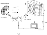
- Fig. 1 shows the block diagram of one of possible embodiments of the system and Fig. 2 shows the block diagram of the second possible embodiment of the described system.
- connection of the system for vector measurement of the electromagnetic field intensity is shown in Fig. 1 .
- the connection here is formed by the microwave generator 1 , which is advantageously tunable. It may be controlled manually but in practice it will preferably be controlled by the computer 2 .
- the microwave output of the microwave generator 1 is connected to the input 31 of the power splitter 3 .
- the first output 32 of the power splitter 3 is connected to the transmitting antenna 4 of the testing channel.
- the second output 33 of the power splitter 3 is via the block 5 controlling the phase and/or magnitude, advantageously controlled by the computer 2 , connected to the transmitting antenna 6 of the reference channel.
- the electromagnetic field radiated by the transmitting antenna 4 of the testing channel is reflected from the examined object 7 , in other possible arrangement in space it passes through or is dispersed by the examined object 7 , and it comes to the individual receiving antennas of the antenna array 8 of the receiving antennas. It means that the radiation pattern of the transmitting antenna 4 of the testing channel is oriented in direction to the examined object 7 and the radiation pattern of the receiving antenna array 8 is oriented also in direction to the examined object 7 .
- the signal a i
- e j ( ⁇ ai ) , i 1...n , where n is the number of the receiving antennas of the antenna array 8 of the receiving antennas.
- Measured power P i depends on the magnitudes of signals
- and on their mutual phase defined as: ⁇ ⁇ i ⁇ ai ⁇ ⁇ bi
- a Multistate reflectometer IEEE Trans. IM., vol. 34, No. 2, pp. 198-201, June 1985 , by means of the computer 2 .
- Higher number of measurements for different settings of the block 5 controlling the phase and/or magnitude advantageously results in more robust measurement. More robust measurement is also achieved by measuring at multiple frequencies of the microwave generator 1 .
- Another possible design solution has the block 5 controlling the phase and/or magnitude connected between the first output 32 of the power splitter 3 and the transmitting antenna 4 of the testing channel. It is also possible to use two blocks 5 controlling the phase and/or magnitude connected between the output 32 of the power splitter 3 and the transmitting antenna 4 of the testing channel and between the second output 33 of the power splitter 3 and the transmitting antenna 6 of the reference channel.
- the transmitting antenna 6 of the reference channel directly radiates to the receiving antenna array 8 , which means that the radiation pattern of the transmitting antenna 6 of the reference channel is oriented in direction to the receiving antenna array 8 and the radiation pattern of the receiving antenna array 8 is oriented in direction to the transmitting antenna 6 of the reference channel.
- Transmitting antenna 4 of the testing channel also directly radiates to the receiving antenna array 8 , which means that the radiation pattern of the transmitting antenna 4 of the testing channel is oriented in direction to the receiving antenna array 8 and the radiation pattern of the receiving antenna array 8 is oriented in direction to the transmitting antenna 4 of the testing channel.
- This arrangement can be used e.g. for measuring the characteristics of unknown antenna connected instead of the transmitting antenna 4 of the testing channel.
- microwave generator 1 instead of one microwave generator 1 another possible design solution uses a system consisting of two microwave generators 1 and 11 with coherent signals at their outputs with the option to set the mutual phase shift ⁇ and the magnitude of these signals, see Fig. 2 .
- This is made possible because between the first microwave generator 1 and the second microwave generator 11 is inserted the block 12 controlling the mutual phase shift and magnitude of coherent signals with the option to control the mutual phase shift and magnitude of these coherent signals by the computer 2 .
- Both microwave generators 1 and 11 may advantageously be tunable.
- the first microwave generator 1 is then directly connected to the transmitting antenna 4 of the testing channel and the second microwave generator 11 is directly connected to the transmitting antenna 6 of the reference channel. Power splitter 3 and the block 5 controlling the phase and/or magnitude are not used in this case because their functions are overtaken directly by the both microwave generators 1 and 11.
- Electromagnetic field radiated by the transmitting antenna 4 of the testing channel reflects from the examined object 7 , in other possible arrangement in space it passes through or is dispersed by the examined object 7 , and it comes to the individual receiving antennas of the antenna array 8 of the receiving antennas. It means that the radiation pattern of the transmitting antenna 4 of the testing channel is oriented in direction to the examined object 7 and the radiation pattern of the receiving antenna array 8 is oriented also in direction to the examined object 7 .
- the signal a i
- e j ( ⁇ ai ) , i 1,...,n , where n is the number of the receiving antennas of the antenna array 8 .
- Measured power P i depends on the magnitudes of signals
- and on their mutual phase shift defined as: ⁇ ⁇ i ⁇ ai ⁇ ⁇ bi
- Phase ⁇ ai was measured with deviation of units of degrees maximum as compared with the measurements made by the vector network analyzer Agilent E8364A.
- System for vector measurement of the electromagnetic field intensity can be industrially applied anywhere where it is necessary to perform vector measurements of the electromagnetic field distribution in space. These may include e.g. a displaying system in the range of microwaves or sub-mm waves. Another possible application is e.g. vector measurements of antennas radiation patterns.
Landscapes
- Physics & Mathematics (AREA)
- Electromagnetism (AREA)
- General Physics & Mathematics (AREA)
- Variable-Direction Aerials And Aerial Arrays (AREA)
Description
- Presented solution deals with the connection of a measuring system for vector measurement of the electromagnetic field intensity distribution in free space.
- For active displaying systems operating with microwaves or even sub-millimeter waves it is necessary, especially for safety applications, to obtain real-time vector data about distribution of intensity of the electromagnetic field on suitable area or in suitable space, which carries information about the examined person or object (examined object). Image of the examined object can then be obtained from the vector information about the electromagnetic field intensity distribution by means of holographic techniques or by synthetic aperture techniques without the need to use lenses or reflectors for focusing. All focusing is done mathematically by the computer image reconstruction technique.
- Electromagnetic field intensity distribution in space can be measured in vectors by a sensor connected to the vector network analyzer (VNA) while its position changes in the given space. The VNA records the values of magnitude and phase of the electromagnetic field intensity in individual points. This solution requires to place the sensor on mechanical positioning system. Inevitably, such measurement is slow and therefore it is not usable e.g. for displaying systems operating in real time.
- For active displaying systems operating in real time were for this reason developed one-dimensional antenna arrays on the systems' receiving part that mechanically scan the second dimension, or directly two-dimensional antenna arrays, as described in D. M. Sheen, D. L. McMakin, T. E. Hall "Three-Dimensional Millimeter-Wave Imaging for Concealed Weapon Detection," IEEE Trans. Microwave Theory Tech., vol. 49, pp. 1581-1592, September 2001, and in F. Friederich, W. Spiegel, M. Bauer, F. Meng, M. D. Thompson, S. Boppel, A. Lisauskas, B. Hils, G. Spickermann, P. H. Bolívar, H. G. Roskos, "THz Active Imaging Systems with Real-Time Capabilities," IEEE Trans. Terahertz Science and Technology, vol. 1, No. 1, pp. 183-200, September 2011.
- Each element of these antenna arrays has a mixer connected behind the receiving antenna and to this mixer is brought a signal from local oscillator. Antenna array therefore requires that the signal from local oscillator is brought to each element of the antenna. Receiving part of the displaying system thus must contain relevant number of power splitters, most commonly binary ones, which split the signal from the local oscillator successively down to the individual antennas mixers. The mixers produce an intermediate frequency signal carrying the information about the magnitude and phase of the electromagnetic field intensity in the place where the antenna is located for subsequent processing. Setback of this design solution is the need to use multiple power splitters based on the number of the antenna array elements, which introduces undesirable losses during the power splitting. Such losses may possibly be compensated by an amplifier before each mixer. The system is complex and therefore also costly. Especially in the sphere of sub-millimeter waves the price is a significant aspect. Receiving antenna matrix thus often contains only a limited number of elements and the required resolution is achieved by complementing the system with mechanically wobbled mirrors.
- There is also another option to process the signal from individual antennas in the antenna array. The signals from individual antennas are successively connected to the VNA input by the electronically switched microwave switchers, as described in the publication Zela J., Hoffmann K., Hudec P., "Errors in Measurement of Microwave Interferograms Using Antenna Matrix", Radioengineering, vol. 17, No. 2, September 2008, pp. 25-32. The system however requires laborious calibration and is usable only at lower microwave frequencies, for which the needed switchers are available. Common disadvantage of both design solutions mentioned above is their complexity and expensiveness.
- Disadvantages mentioned above are removed by the system for vector measurement of the electromagnetic field intensity according to the presented solution, as defined in
claims 1 and 4. Such a system comprises a transmitting antenna, microwave generator and the antenna array of receiving antennas where the outputs of the individual antennas in the receiving antenna array are via the power sensors connected directly or through the block of switches to the A/D converter connected to the computer controlling the block of switches. The principle of the new solution is creation of two channels with two transmitting antennas. One channel is a testing channel with the transmitting antenna of the testing channel connected to the microwave output of the microwave generator via the first output of the power splitter. The second channel is a reference channel with the transmitting antenna of the reference channel. The transmitting antenna of the reference channel is connected to the microwave output of the microwave generator via the second output of the power splitter. The block controlling the phase and/or magnitude is connected between the first output of the power splitter and the transmitting antenna of the testing channel and/or between the second output of the power splitter and the transmitting antenna of the reference channel. Transmitting antenna of the testing channel, transmitting antenna of the reference channel and the receiving antenna array are placed in space in one of the following arrangements. In one arrangement the radiation pattern of the transmitting antenna of the testing channel and the radiation pattern of the transmitting antenna of the reference channel are oriented in direction to the receiving antenna array and simultaneously the radiation pattern of the receiving antenna array is oriented in direction to the transmitting antenna of the testing channel and to the transmitting antenna of the reference channel. In the second arrangement the radiation pattern of the transmitting antenna of the testing channel is oriented in direction to the examined object and the radiation pattern of the transmitting antenna of the reference channel is oriented in direction to the receiving antenna array and the radiation pattern of the receiving antenna array is oriented in direction to the examined object and to the transmitting antenna of the reference channel. - In an advantageous embodiment the block controlling the phase and/or magnitude is interconnected with the computer. Advantageously, the microwave generator is tunable.
- The second possible embodiment of the same system is that it again consists of the testing channel with the transmitting antenna of the testing channel and the reference channel with the transmitting antenna of the reference channel. Transmitting antenna of the testing channel is connected to the microwave output of the first microwave generator and the transmitting antenna of the reference channel is connected to the microwave output of the second microwave generator, while its signal is coherent with the signal of the first microwave generator. The first and second microwave generators are interconnected with the block controlling mutual phase shift and the magnitude of the coherent signals with the option to set the mutual phase shift and magnitude of these coherent signals by the computer. Again, this embodiment allows two arrangements of the transmitting and receiving antennas. In the first arrangement the transmitting antenna of the testing channel, the transmitting antenna of the reference channel and the receiving antenna array are placed in space in such a way that the radiation pattern of the transmitting antenna of the testing channel and radiation pattern of the transmitting antenna of the reference channel are oriented in direction to the receiving antenna array and simultaneously the radiation pattern of the receiving antenna array is oriented in direction to the transmitting antenna of the testing channel and the transmitting antenna of the reference channel. In the second arrangement the radiation pattern of the transmitting antenna of the testing channel is oriented in direction to the examined object and the transmitting antenna of the reference channel is oriented in direction to the receiving antenna array and simultaneously the radiation pattern of the receiving antenna array is oriented in direction to the examined object and the transmitting antenna of the reference channel. Advantageously, the first and the second microwave generator are tunable.
- The advantage of this connection is that it allows for vector measurement of the electromagnetic field intensity without the need to distribute the microwave signal of the local oscillator to the mixers of individual antennas of the receiving antenna array through microwave network structure consisting of many power splitters as it is necessary for the existing measuring systems. Therefore, the receiving antenna array can be realized in an easier and less expensive way.
-
Fig. 1 shows the block diagram of one of possible embodiments of the system andFig. 2 shows the block diagram of the second possible embodiment of the described system. - One possible example of connection of the system for vector measurement of the electromagnetic field intensity is shown in
Fig. 1 . The connection here is formed by themicrowave generator 1, which is advantageously tunable. It may be controlled manually but in practice it will preferably be controlled by thecomputer 2. The microwave output of themicrowave generator 1 is connected to theinput 31 of thepower splitter 3. Thefirst output 32 of thepower splitter 3 is connected to the transmitting antenna 4 of the testing channel. Thesecond output 33 of thepower splitter 3 is via the block 5 controlling the phase and/or magnitude, advantageously controlled by thecomputer 2, connected to the transmittingantenna 6 of the reference channel. The electromagnetic field radiated by the transmitting antenna 4 of the testing channel is reflected from the examinedobject 7, in other possible arrangement in space it passes through or is dispersed by the examinedobject 7, and it comes to the individual receiving antennas of theantenna array 8 of the receiving antennas. It means that the radiation pattern of the transmitting antenna 4 of the testing channel is oriented in direction to the examinedobject 7 and the radiation pattern of thereceiving antenna array 8 is oriented also in direction to the examinedobject 7. At the output of the i-th receiving antenna of theantenna array 8 of the receiving antennas is generated the signal ai =|ai |e j(ϕai ), i=1...n, where n is the number of the receiving antennas of theantenna array 8 of the receiving antennas. Simultaneously, each i-th receiving antenna of theantenna array 8 receives coherent electromagnetic field radiated by the transmittingantenna 6 of the reference channel, which at its output generates the signal bi = |bi |e j(ϕbi ) It means that the radiation pattern of the transmittingantenna 6 of the reference channel is oriented in direction to the receivingantenna array 8 and the radiation pattern of the receivingantenna array 8 is oriented in direction to the transmittingantenna 6 of the reference channel. The output of each receiving antenna is connected to the power sensor D i, for example to the detector, and the measured received power is defined by the formula:
- Relevant DC voltage at the output of each detector D i is then successively brought via the
block 9 of switchers controlled by thecomputer 2 to the A/D converter 10 connected to thecomputer 2. - Measured power Pi depends on the magnitudes of signals |ai | and |bi | and on their mutual phase defined as:

- Phase of the reference signal ϕbi and/or magnitude |bi | can be changed in a defined way by means of the block 5 controlling the phase and/or magnitude. Its every single setting corresponds to one equation (1). Minimum four different equations (1) are needed to distinctively determine the signal ai = |ai |e j(ϕai ), and therefore also the magnitude and phase of the measured electromagnetic field intensity in the place where the receiving antenna is located by methodology compliant with Engen, G. F., "The Six-Port Reflectometer: An Alternative Network Analyzer," IEEE Trans. Microwave Theory Tech., vol. 25, pp. 1075-1080, December 1997 or Oldfield, L. C., Ide, J. P., and Griffin, E. J. "A Multistate reflectometer", IEEE Trans. IM., vol. 34, No. 2, pp. 198-201, June 1985, by means of the
computer 2. Higher number of measurements for different settings of the block 5 controlling the phase and/or magnitude advantageously results in more robust measurement. More robust measurement is also achieved by measuring at multiple frequencies of themicrowave generator 1. - Another possible design solution has the block 5 controlling the phase and/or magnitude connected between the
first output 32 of thepower splitter 3 and the transmitting antenna 4 of the testing channel. It is also possible to use two blocks 5 controlling the phase and/or magnitude connected between theoutput 32 of thepower splitter 3 and the transmitting antenna 4 of the testing channel and between thesecond output 33 of thepower splitter 3 and the transmittingantenna 6 of the reference channel. - In another possible design solution the transmitting
antenna 6 of the reference channel directly radiates to the receivingantenna array 8, which means that the radiation pattern of the transmittingantenna 6 of the reference channel is oriented in direction to the receivingantenna array 8 and the radiation pattern of the receivingantenna array 8 is oriented in direction to the transmittingantenna 6 of the reference channel. Transmitting antenna 4 of the testing channel also directly radiates to the receivingantenna array 8, which means that the radiation pattern of the transmitting antenna 4 of the testing channel is oriented in direction to the receivingantenna array 8 and the radiation pattern of the receivingantenna array 8 is oriented in direction to the transmitting antenna 4 of the testing channel. This arrangement can be used e.g. for measuring the characteristics of unknown antenna connected instead of the transmitting antenna 4 of the testing channel. - Instead of one
microwave generator 1 another possible design solution uses a system consisting of twomicrowave generators Fig. 2 . This is made possible because between thefirst microwave generator 1 and thesecond microwave generator 11 is inserted theblock 12 controlling the mutual phase shift and magnitude of coherent signals with the option to control the mutual phase shift and magnitude of these coherent signals by thecomputer 2. Bothmicrowave generators first microwave generator 1 is then directly connected to the transmitting antenna 4 of the testing channel and thesecond microwave generator 11 is directly connected to the transmittingantenna 6 of the reference channel.Power splitter 3 and the block 5 controlling the phase and/or magnitude are not used in this case because their functions are overtaken directly by the bothmicrowave generators - Electromagnetic field radiated by the transmitting antenna 4 of the testing channel reflects from the examined
object 7, in other possible arrangement in space it passes through or is dispersed by the examinedobject 7, and it comes to the individual receiving antennas of theantenna array 8 of the receiving antennas. It means that the radiation pattern of the transmitting antenna 4 of the testing channel is oriented in direction to the examinedobject 7 and the radiation pattern of the receivingantenna array 8 is oriented also in direction to the examinedobject 7. At the output of the i-th antenna is generated the signal ai = |ai |e j(ϕai ), i=1,...,n, where n is the number of the receiving antennas of theantenna array 8. Simultaneously, each i-th receiving antenna of theantenna array 8 receives coherent electromagnetic field radiated by the transmittingantenna 6 of the reference channel, which at its output generates the signal bi = |bi |e j(ϕbi ), It means that the radiation pattern of the transmittingantenna 6 of the reference channel is oriented in direction to the receivingantenna array 8 and the radiation pattern of the receivingantenna array 8 is oriented in direction to the transmittingantenna 6 of the reference channel. The output of each receiving antenna is connected to the power sensor D i, for example to the detector, and the measured received power is defined by the formula:
- Relevant DC voltage at the output of each detector D i is then successively brought via the
block 9 of switchers controlled by thecomputer 2 to the A/D converter 10 connected to thecomputer 2. - Measured power Pi depends on the magnitudes of signals |ai | and |bi | and on their mutual phase shift defined as:

- Phase of the reference signal ϕbi and/or magnitude |bi | can be changed in a defined way by setting the phase shift Δϕ between the coherent signals of the
first microwave generator 1 and thesecond microwave generator 11 by changing the signal phase and/or magnitude of thesecond microwave generator 11. Its every single setting corresponds to one equation (3). Minimum four different equations (3) are needed to distinctively determine the signal ai = |ai |e j(ϕai ), and therefore also the magnitude and phase of the measured electromagnetic field intensity in the place where the receiving antenna is located by the same methodology as in the previous case, all controlled by thecomputer 2. Higher number of measurements for different settings of theblock 12 controlling the phase and/or magnitude advantageously results in more robust measurement. More robust measurement is also achieved by measuring at multiple frequencies of themicrowave generators - In another possible arrangement the functions of the
microwave generators - It is also possible to create an arrangement where the signal phase and/or magnitude change at both
microwave generators - Properties of the measuring system were experimentally tested within the frequency range 8-12 GHz. Phase ϕai was measured with deviation of units of degrees maximum as compared with the measurements made by the vector network analyzer Agilent E8364A.
- System for vector measurement of the electromagnetic field intensity can be industrially applied anywhere where it is necessary to perform vector measurements of the electromagnetic field distribution in space. These may include e.g. a displaying system in the range of microwaves or sub-mm waves. Another possible application is e.g. vector measurements of antennas radiation patterns.
Claims (5)
- System for vector measurement of the electromagnetic field intensity, said system comprising a transmitting antenna (4) of a testing channel, a microwave generator (1), an antenna array (8) of receiving antennas having outputs of individual antennas, power sensors (Di), a block (9) of switches, an A/D converter (10), a computer (2), a power splitter (3) having a first output (32) and a second output (33) and a transmitting antenna (6) of a reference channel, where the outputs of individual antennas of the antenna array (8) are via said power sensors (Di) connected directly or through the block (9) of switches to the A/D converter (10) interconnected with the computer (2) controlling the block (9) of switches, a testing channel being formed by the transmitting antenna (4) of the testing channel connected to the microwave output of the microwave generator (1) via the first output (32) of the power splitter (3) and a reference channel being formed by the transmitting antenna (6) of the reference channel, which is connected to the microwave output of the microwave generator (1) via the second output (33) of the power splitter (3), characterised in that between the first output (32) of the power splitter (3) and the transmitting antenna (4) of the testing channel and/or between the second output (33) of the power splitter (3) and the transmitting antenna (6) of the reference channel is connected a block (5) controlling the phase and/or magnitude, while the transmitting antenna (4) of the testing channel, transmitting antenna (6) of the reference channel and the receiving antenna array (8) are placed in space in such a way that the radiation pattern of the transmitting antenna (4) of the testing channel and the radiation pattern of the transmitting antenna (6) of the reference channel are oriented in direction to the receiving antenna array (8) and simultaneously the radiation pattern of the receiving antenna array (8) is oriented in direction to the transmitting antenna (4) of the testing channel and to the transmitting antenna (6) of the reference channel, or the radiation pattern of the transmitting antenna (4) of the testing channel is oriented in direction to the examined object (7) and the radiation pattern of the transmitting antenna (6) of the reference channel is oriented in direction to the receiving antenna array (8) and the radiation pattern of the receiving antenna array (8) is oriented in direction to the examined object (7) and the transmitting antenna (6) of the reference channel.
- System according to claim 1 characterized by the fact that the block (5) controlling the phase and/or magnitude is interconnected with the computer (2).
- System according to claim 1 or 2 characterized by the fact that the microwave generator (1) is tunable.
- System for vector measurement of the electromagnetic field intensity, said system comprising a transmitting antenna (4) of a testing channel, a first microwave generator (1), an antenna array (8) of receiving antennas having outputs of individual antennas, power sensors (Di), a block (9) of switches, an A/D converter (10), a computer (2) and a transmitting antenna (6) of a reference channel, where the outputs of individual antennas of the receiving antenna array (8) are via power sensors (Di) connected directly or through the block (9) of switches to the A/D converter (10) interconnected with the computer (2) controlling the block (9) of switches, a testing channel being formed by the transmitting antenna (4) of the testing channel connected to the microwave output of the first microwave generator (1) and a reference channel being formed by the transmitting antenna (6) of the reference channel, characterised in that said system further comprises a second microwave generator (11), the transmitting antenna (6) of the reference channel being connected to a microwave output of the second microwave generator (11), the signal of the second microwave generator (11) being coherent with the signal of the first microwave generator (1), where the first microwave generator (1) and the second microwave generator (11) are interconnected with a block (12) controlling the mutual phase shift and magnitude of their coherent signals with the option to set the mutual phase shift and magnitude of these coherent signals by the computer (2), while the transmitting antenna (4) of the testing channel, transmitting antenna (6) of the reference channel and the receiving antenna array (8) are placed in space in such a way that the radiation pattern of the transmitting antenna (4) of the testing channel and the radiation pattern of the transmitting antenna (6) of the reference channel are oriented in direction to the receiving antenna array (8) and simultaneously the radiation pattern of the receiving antenna array (8) is oriented in direction to the transmitting antenna (4) of the testing channel and the transmitting antenna (6) of the reference channel, or the radiation pattern of the transmitting antenna (4) of the testing channel is oriented in direction to the examined object (7) and the radiation pattern of the transmitting antenna (6) of the reference channel is oriented in direction to the receiving antenna array (8) and the radiation pattern of the receiving antenna array (8) is oriented in direction to the examined object (7) and the transmitting antenna (6) of the reference channel.
- System according to claim 4 characterized by the fact that the first microwave generator (1) and the second microwave generator (11) are tunable.
Applications Claiming Priority (1)
| Application Number | Priority Date | Filing Date | Title |
|---|---|---|---|
| CZ2013-396A CZ304613B6 (en) | 2013-05-29 | 2013-05-29 | System for vector measurement of electromagnetic field intensity |
Publications (2)
| Publication Number | Publication Date |
|---|---|
| EP2811307A1 EP2811307A1 (en) | 2014-12-10 |
| EP2811307B1 true EP2811307B1 (en) | 2017-02-15 |
Family
ID=50774753
Family Applications (1)
| Application Number | Title | Priority Date | Filing Date |
|---|---|---|---|
| EP14169931.4A Not-in-force EP2811307B1 (en) | 2013-05-29 | 2014-05-27 | System for vector measurement of the electromagnetic field intensity |
Country Status (2)
| Country | Link |
|---|---|
| EP (1) | EP2811307B1 (en) |
| CZ (1) | CZ304613B6 (en) |
Families Citing this family (5)
| Publication number | Priority date | Publication date | Assignee | Title |
|---|---|---|---|---|
| DE102015001002B4 (en) * | 2015-01-27 | 2018-12-27 | Kathrein Se | Near field measurement of active antenna systems |
| CN106872798B (en) * | 2017-01-23 | 2021-05-04 | 国家电网公司 | A method of array signal filtering and amplitude detection |
| CN114137481B (en) * | 2021-09-18 | 2025-07-04 | 北京航空航天大学 | An electromagnetic scattering test system and method based on low-frequency cylindrical source antenna array |
| CN115236419B (en) * | 2022-09-19 | 2022-12-02 | 中汽研新能源汽车检验中心(天津)有限公司 | Electric field intensity calibration method for actual electromagnetic environment signal |
| CN117969998B (en) * | 2024-01-29 | 2025-10-31 | 奇瑞汽车股份有限公司 | Immunity test device, immunity test method, device and storage medium |
Family Cites Families (11)
| Publication number | Priority date | Publication date | Assignee | Title |
|---|---|---|---|---|
| US5455590A (en) * | 1991-08-30 | 1995-10-03 | Battelle Memorial Institute | Real-time holographic surveillance system |
| JPH06331672A (en) * | 1993-05-19 | 1994-12-02 | Yokohama Rubber Co Ltd:The | Electromagnetic wave shield performance measurement method |
| JPH11264851A (en) * | 1998-03-18 | 1999-09-28 | Tdk Corp | Measuring apparatus for electric field strengh |
| GB2339917A (en) * | 1998-07-21 | 2000-02-09 | Ifr Limited | Generating a multitone test signal |
| US6753690B2 (en) * | 1998-11-30 | 2004-06-22 | Poseidon Scientific Instruments Pty Ltd | Interferometric signal processing apparatus |
| JP2003107116A (en) * | 2001-09-28 | 2003-04-09 | Hitachi Ltd | Electromagnetic Wave Source Search Method, Program for Electromagnetic Wave Source Search, and Exploration Antenna Used for Electromagnetic Wave Source Search |
| US20040196083A1 (en) * | 2003-04-02 | 2004-10-07 | Dunsmore Joel P. | System and method for generating balanced signals with arbitrary amplitude and phase control using modulation |
| JP2006074350A (en) * | 2004-09-01 | 2006-03-16 | Advanced Telecommunication Research Institute International | Beam pattern calculation device |
| GB2459218B (en) * | 2005-06-13 | 2010-01-06 | Wireless Fibre Systems Ltd | Underwater signal direction determination |
| JP4915565B2 (en) * | 2006-10-25 | 2012-04-11 | 秋田県 | Electromagnetic field measurement system |
| DE102011079421B4 (en) * | 2011-07-19 | 2014-01-16 | Continental Automotive Gmbh | Method and arrangement for access and / or start authentication |
-
2013
- 2013-05-29 CZ CZ2013-396A patent/CZ304613B6/en not_active IP Right Cessation
-
2014
- 2014-05-27 EP EP14169931.4A patent/EP2811307B1/en not_active Not-in-force
Also Published As
| Publication number | Publication date |
|---|---|
| CZ2013396A3 (en) | 2014-07-30 |
| CZ304613B6 (en) | 2014-07-30 |
| EP2811307A1 (en) | 2014-12-10 |
Similar Documents
| Publication | Publication Date | Title |
|---|---|---|
| JP4376778B2 (en) | Terahertz image processing apparatus and terahertz image processing method | |
| EP2811307B1 (en) | System for vector measurement of the electromagnetic field intensity | |
| US10948580B2 (en) | Object sensing device and object sensing method | |
| US20190187266A1 (en) | Object detection apparatus and object detection method | |
| Amineh et al. | Three‐dimensional microwave holographic imaging employing forward‐scattered waves only | |
| Alvarez et al. | Inverse scattering for monochromatic phaseless measurements | |
| Baccouche et al. | A sparse array based sub-terahertz imaging system for volume inspection | |
| López et al. | On the use of an equivalent currents-based technique to improve electromagnetic imaging | |
| EP2914926B1 (en) | Three-dimensional holographical imaging | |
| López et al. | A portable cost-effective amplitude and phase antenna measurement system | |
| Bassli et al. | 3-D imaging of materials at 0.1 THz for inner-defect detection using a frequency-modulated continuous-wave radar | |
| Sukhanov et al. | Reconstruction of 3D radio images from multifrequency holographic measurements | |
| Laviada et al. | Broadband synthetic aperture scanning system for three-dimensional through-the-wall inspection | |
| Tajik et al. | Real-time quantitative reconstruction based on microwave holography | |
| Costanzo et al. | Spatial domain indirect holographic technique for antenna near-field phaseless measurements | |
| US20160266052A1 (en) | Rapid microwave phase detection with a solid state device | |
| US12078727B2 (en) | Imaging system and method for material characterization of a sample | |
| Kravchenko et al. | Multiantenna radiometric complex for high resolution imaging: Synthesis of algorithm for optimal UWB signal processing and development of functional flow block diagram | |
| Drobakhin | A novel approach to six-port reflectometer analysis | |
| Leino et al. | Millimeter-wave frequency-diverse imaging with phased array intended for communications | |
| Li et al. | Performance evaluation of a passive millimeter-wave imager | |
| Mizrakhy et al. | Investigation of polarization back-scattering characteristics of metal cube in sub-THz frequency range by the quasi-optical waveguide modeling method | |
| Jandt et al. | Radar imaging based on multiple non-coherent antennas | |
| Essen et al. | A four-element 80-GHz luggage scanner based on the synthetic aperture radar principle | |
| RU144400U1 (en) | RADIOLOGOGRAPHIC ULTRAWIDEBAND TOMOGRAPH |
Legal Events
| Date | Code | Title | Description |
|---|---|---|---|
| PUAI | Public reference made under article 153(3) epc to a published international application that has entered the european phase |
Free format text: ORIGINAL CODE: 0009012 |
|
| 17P | Request for examination filed |
Effective date: 20140527 |
|
| AK | Designated contracting states |
Kind code of ref document: A1 Designated state(s): AL AT BE BG CH CY CZ DE DK EE ES FI FR GB GR HR HU IE IS IT LI LT LU LV MC MK MT NL NO PL PT RO RS SE SI SK SM TR |
|
| AX | Request for extension of the european patent |
Extension state: BA ME |
|
| R17P | Request for examination filed (corrected) |
Effective date: 20140602 |
|
| GRAP | Despatch of communication of intention to grant a patent |
Free format text: ORIGINAL CODE: EPIDOSNIGR1 |
|
| INTG | Intention to grant announced |
Effective date: 20160729 |
|
| GRAS | Grant fee paid |
Free format text: ORIGINAL CODE: EPIDOSNIGR3 |
|
| RIN1 | Information on inventor provided before grant (corrected) |
Inventor name: HOFFMANN, KAREL |
|
| GRAA | (expected) grant |
Free format text: ORIGINAL CODE: 0009210 |
|
| AK | Designated contracting states |
Kind code of ref document: B1 Designated state(s): AL AT BE BG CH CY CZ DE DK EE ES FI FR GB GR HR HU IE IS IT LI LT LU LV MC MK MT NL NO PL PT RO RS SE SI SK SM TR |
|
| REG | Reference to a national code |
Ref country code: CH Ref legal event code: EP Ref country code: GB Ref legal event code: FG4D |
|
| REG | Reference to a national code |
Ref country code: IE Ref legal event code: FG4D |
|
| REG | Reference to a national code |
Ref country code: AT Ref legal event code: REF Ref document number: 868197 Country of ref document: AT Kind code of ref document: T Effective date: 20170315 |
|
| REG | Reference to a national code |
Ref country code: DE Ref legal event code: R096 Ref document number: 602014006764 Country of ref document: DE |
|
| REG | Reference to a national code |
Ref country code: NL Ref legal event code: MP Effective date: 20170215 |
|
| REG | Reference to a national code |
Ref country code: LT Ref legal event code: MG4D |
|
| REG | Reference to a national code |
Ref country code: AT Ref legal event code: MK05 Ref document number: 868197 Country of ref document: AT Kind code of ref document: T Effective date: 20170215 |
|
| PG25 | Lapsed in a contracting state [announced via postgrant information from national office to epo] |
Ref country code: GR Free format text: LAPSE BECAUSE OF FAILURE TO SUBMIT A TRANSLATION OF THE DESCRIPTION OR TO PAY THE FEE WITHIN THE PRESCRIBED TIME-LIMIT Effective date: 20170516 Ref country code: HR Free format text: LAPSE BECAUSE OF FAILURE TO SUBMIT A TRANSLATION OF THE DESCRIPTION OR TO PAY THE FEE WITHIN THE PRESCRIBED TIME-LIMIT Effective date: 20170215 Ref country code: FI Free format text: LAPSE BECAUSE OF FAILURE TO SUBMIT A TRANSLATION OF THE DESCRIPTION OR TO PAY THE FEE WITHIN THE PRESCRIBED TIME-LIMIT Effective date: 20170215 Ref country code: NO Free format text: LAPSE BECAUSE OF FAILURE TO SUBMIT A TRANSLATION OF THE DESCRIPTION OR TO PAY THE FEE WITHIN THE PRESCRIBED TIME-LIMIT Effective date: 20170515 Ref country code: LT Free format text: LAPSE BECAUSE OF FAILURE TO SUBMIT A TRANSLATION OF THE DESCRIPTION OR TO PAY THE FEE WITHIN THE PRESCRIBED TIME-LIMIT Effective date: 20170215 |
|
| PG25 | Lapsed in a contracting state [announced via postgrant information from national office to epo] |
Ref country code: LV Free format text: LAPSE BECAUSE OF FAILURE TO SUBMIT A TRANSLATION OF THE DESCRIPTION OR TO PAY THE FEE WITHIN THE PRESCRIBED TIME-LIMIT Effective date: 20170215 Ref country code: RS Free format text: LAPSE BECAUSE OF FAILURE TO SUBMIT A TRANSLATION OF THE DESCRIPTION OR TO PAY THE FEE WITHIN THE PRESCRIBED TIME-LIMIT Effective date: 20170215 Ref country code: SE Free format text: LAPSE BECAUSE OF FAILURE TO SUBMIT A TRANSLATION OF THE DESCRIPTION OR TO PAY THE FEE WITHIN THE PRESCRIBED TIME-LIMIT Effective date: 20170215 Ref country code: PT Free format text: LAPSE BECAUSE OF FAILURE TO SUBMIT A TRANSLATION OF THE DESCRIPTION OR TO PAY THE FEE WITHIN THE PRESCRIBED TIME-LIMIT Effective date: 20170615 Ref country code: BG Free format text: LAPSE BECAUSE OF FAILURE TO SUBMIT A TRANSLATION OF THE DESCRIPTION OR TO PAY THE FEE WITHIN THE PRESCRIBED TIME-LIMIT Effective date: 20170515 Ref country code: AT Free format text: LAPSE BECAUSE OF FAILURE TO SUBMIT A TRANSLATION OF THE DESCRIPTION OR TO PAY THE FEE WITHIN THE PRESCRIBED TIME-LIMIT Effective date: 20170215 Ref country code: ES Free format text: LAPSE BECAUSE OF FAILURE TO SUBMIT A TRANSLATION OF THE DESCRIPTION OR TO PAY THE FEE WITHIN THE PRESCRIBED TIME-LIMIT Effective date: 20170215 Ref country code: LU Free format text: LAPSE BECAUSE OF NON-PAYMENT OF DUE FEES Effective date: 20170531 Ref country code: NL Free format text: LAPSE BECAUSE OF FAILURE TO SUBMIT A TRANSLATION OF THE DESCRIPTION OR TO PAY THE FEE WITHIN THE PRESCRIBED TIME-LIMIT Effective date: 20170215 |
|
| PG25 | Lapsed in a contracting state [announced via postgrant information from national office to epo] |
Ref country code: SK Free format text: LAPSE BECAUSE OF FAILURE TO SUBMIT A TRANSLATION OF THE DESCRIPTION OR TO PAY THE FEE WITHIN THE PRESCRIBED TIME-LIMIT Effective date: 20170215 Ref country code: CZ Free format text: LAPSE BECAUSE OF FAILURE TO SUBMIT A TRANSLATION OF THE DESCRIPTION OR TO PAY THE FEE WITHIN THE PRESCRIBED TIME-LIMIT Effective date: 20170215 Ref country code: RO Free format text: LAPSE BECAUSE OF FAILURE TO SUBMIT A TRANSLATION OF THE DESCRIPTION OR TO PAY THE FEE WITHIN THE PRESCRIBED TIME-LIMIT Effective date: 20170215 Ref country code: IT Free format text: LAPSE BECAUSE OF FAILURE TO SUBMIT A TRANSLATION OF THE DESCRIPTION OR TO PAY THE FEE WITHIN THE PRESCRIBED TIME-LIMIT Effective date: 20170215 Ref country code: EE Free format text: LAPSE BECAUSE OF FAILURE TO SUBMIT A TRANSLATION OF THE DESCRIPTION OR TO PAY THE FEE WITHIN THE PRESCRIBED TIME-LIMIT Effective date: 20170215 |
|
| REG | Reference to a national code |
Ref country code: DE Ref legal event code: R097 Ref document number: 602014006764 Country of ref document: DE |
|
| PG25 | Lapsed in a contracting state [announced via postgrant information from national office to epo] |
Ref country code: PL Free format text: LAPSE BECAUSE OF FAILURE TO SUBMIT A TRANSLATION OF THE DESCRIPTION OR TO PAY THE FEE WITHIN THE PRESCRIBED TIME-LIMIT Effective date: 20170215 Ref country code: DK Free format text: LAPSE BECAUSE OF FAILURE TO SUBMIT A TRANSLATION OF THE DESCRIPTION OR TO PAY THE FEE WITHIN THE PRESCRIBED TIME-LIMIT Effective date: 20170215 Ref country code: SM Free format text: LAPSE BECAUSE OF FAILURE TO SUBMIT A TRANSLATION OF THE DESCRIPTION OR TO PAY THE FEE WITHIN THE PRESCRIBED TIME-LIMIT Effective date: 20170215 |
|
| PLBE | No opposition filed within time limit |
Free format text: ORIGINAL CODE: 0009261 |
|
| STAA | Information on the status of an ep patent application or granted ep patent |
Free format text: STATUS: NO OPPOSITION FILED WITHIN TIME LIMIT |
|
| REG | Reference to a national code |
Ref country code: CH Ref legal event code: PL |
|
| 26N | No opposition filed |
Effective date: 20171116 |
|
| PG25 | Lapsed in a contracting state [announced via postgrant information from national office to epo] |
Ref country code: MC Free format text: LAPSE BECAUSE OF FAILURE TO SUBMIT A TRANSLATION OF THE DESCRIPTION OR TO PAY THE FEE WITHIN THE PRESCRIBED TIME-LIMIT Effective date: 20170215 |
|
| REG | Reference to a national code |
Ref country code: IE Ref legal event code: MM4A |
|
| PG25 | Lapsed in a contracting state [announced via postgrant information from national office to epo] |
Ref country code: CH Free format text: LAPSE BECAUSE OF NON-PAYMENT OF DUE FEES Effective date: 20170531 Ref country code: LI Free format text: LAPSE BECAUSE OF NON-PAYMENT OF DUE FEES Effective date: 20170531 Ref country code: SI Free format text: LAPSE BECAUSE OF FAILURE TO SUBMIT A TRANSLATION OF THE DESCRIPTION OR TO PAY THE FEE WITHIN THE PRESCRIBED TIME-LIMIT Effective date: 20170215 |
|
| REG | Reference to a national code |
Ref country code: FR Ref legal event code: ST Effective date: 20180131 |
|
| PG25 | Lapsed in a contracting state [announced via postgrant information from national office to epo] |
Ref country code: LU Free format text: LAPSE BECAUSE OF NON-PAYMENT OF DUE FEES Effective date: 20170527 |
|
| REG | Reference to a national code |
Ref country code: BE Ref legal event code: MM Effective date: 20170531 |
|
| PG25 | Lapsed in a contracting state [announced via postgrant information from national office to epo] |
Ref country code: IE Free format text: LAPSE BECAUSE OF NON-PAYMENT OF DUE FEES Effective date: 20170527 |
|
| PG25 | Lapsed in a contracting state [announced via postgrant information from national office to epo] |
Ref country code: FR Free format text: LAPSE BECAUSE OF NON-PAYMENT OF DUE FEES Effective date: 20170531 |
|
| PG25 | Lapsed in a contracting state [announced via postgrant information from national office to epo] |
Ref country code: BE Free format text: LAPSE BECAUSE OF NON-PAYMENT OF DUE FEES Effective date: 20170531 |
|
| PG25 | Lapsed in a contracting state [announced via postgrant information from national office to epo] |
Ref country code: MT Free format text: LAPSE BECAUSE OF NON-PAYMENT OF DUE FEES Effective date: 20170527 |
|
| PG25 | Lapsed in a contracting state [announced via postgrant information from national office to epo] |
Ref country code: HU Free format text: LAPSE BECAUSE OF FAILURE TO SUBMIT A TRANSLATION OF THE DESCRIPTION OR TO PAY THE FEE WITHIN THE PRESCRIBED TIME-LIMIT; INVALID AB INITIO Effective date: 20140527 |
|
| PGFP | Annual fee paid to national office [announced via postgrant information from national office to epo] |
Ref country code: DE Payment date: 20190506 Year of fee payment: 6 |
|
| PG25 | Lapsed in a contracting state [announced via postgrant information from national office to epo] |
Ref country code: CY Free format text: LAPSE BECAUSE OF FAILURE TO SUBMIT A TRANSLATION OF THE DESCRIPTION OR TO PAY THE FEE WITHIN THE PRESCRIBED TIME-LIMIT Effective date: 20170215 |
|
| PGFP | Annual fee paid to national office [announced via postgrant information from national office to epo] |
Ref country code: GB Payment date: 20190506 Year of fee payment: 6 |
|
| PG25 | Lapsed in a contracting state [announced via postgrant information from national office to epo] |
Ref country code: MK Free format text: LAPSE BECAUSE OF FAILURE TO SUBMIT A TRANSLATION OF THE DESCRIPTION OR TO PAY THE FEE WITHIN THE PRESCRIBED TIME-LIMIT Effective date: 20170215 |
|
| PG25 | Lapsed in a contracting state [announced via postgrant information from national office to epo] |
Ref country code: TR Free format text: LAPSE BECAUSE OF FAILURE TO SUBMIT A TRANSLATION OF THE DESCRIPTION OR TO PAY THE FEE WITHIN THE PRESCRIBED TIME-LIMIT Effective date: 20170215 |
|
| PG25 | Lapsed in a contracting state [announced via postgrant information from national office to epo] |
Ref country code: AL Free format text: LAPSE BECAUSE OF FAILURE TO SUBMIT A TRANSLATION OF THE DESCRIPTION OR TO PAY THE FEE WITHIN THE PRESCRIBED TIME-LIMIT Effective date: 20170215 Ref country code: IS Free format text: LAPSE BECAUSE OF FAILURE TO SUBMIT A TRANSLATION OF THE DESCRIPTION OR TO PAY THE FEE WITHIN THE PRESCRIBED TIME-LIMIT Effective date: 20170615 |
|
| REG | Reference to a national code |
Ref country code: DE Ref legal event code: R119 Ref document number: 602014006764 Country of ref document: DE |
|
| GBPC | Gb: european patent ceased through non-payment of renewal fee |
Effective date: 20200527 |
|
| PG25 | Lapsed in a contracting state [announced via postgrant information from national office to epo] |
Ref country code: GB Free format text: LAPSE BECAUSE OF NON-PAYMENT OF DUE FEES Effective date: 20200527 |
|
| PG25 | Lapsed in a contracting state [announced via postgrant information from national office to epo] |
Ref country code: DE Free format text: LAPSE BECAUSE OF NON-PAYMENT OF DUE FEES Effective date: 20201201 |