EP2811314A1 - Dispositif de mesure du champ magnétique avec compensation des vibrations - Google Patents
Dispositif de mesure du champ magnétique avec compensation des vibrations Download PDFInfo
- Publication number
- EP2811314A1 EP2811314A1 EP13170893.5A EP13170893A EP2811314A1 EP 2811314 A1 EP2811314 A1 EP 2811314A1 EP 13170893 A EP13170893 A EP 13170893A EP 2811314 A1 EP2811314 A1 EP 2811314A1
- Authority
- EP
- European Patent Office
- Prior art keywords
- magnetic field
- measuring device
- bending beam
- holding body
- field measuring
- Prior art date
- Legal status (The legal status is an assumption and is not a legal conclusion. Google has not performed a legal analysis and makes no representation as to the accuracy of the status listed.)
- Granted
Links
Images


Classifications
-
- G—PHYSICS
- G01—MEASURING; TESTING
- G01R—MEASURING ELECTRIC VARIABLES; MEASURING MAGNETIC VARIABLES
- G01R33/00—Arrangements or instruments for measuring magnetic variables
- G01R33/12—Measuring magnetic properties of articles or specimens of solids or fluids
- G01R33/18—Measuring magnetostrictive properties
-
- B—PERFORMING OPERATIONS; TRANSPORTING
- B81—MICROSTRUCTURAL TECHNOLOGY
- B81B—MICROSTRUCTURAL DEVICES OR SYSTEMS, e.g. MICROMECHANICAL DEVICES
- B81B3/00—Devices comprising flexible or deformable elements, e.g. comprising elastic tongues or membranes
- B81B3/0018—Structures acting upon the moving or flexible element for transforming energy into mechanical movement or vice versa, i.e. actuators, sensors, generators
- B81B3/0021—Transducers for transforming electrical into mechanical energy or vice versa
-
- G—PHYSICS
- G01—MEASURING; TESTING
- G01R—MEASURING ELECTRIC VARIABLES; MEASURING MAGNETIC VARIABLES
- G01R33/00—Arrangements or instruments for measuring magnetic variables
- G01R33/0005—Geometrical arrangement of magnetic sensor elements; Apparatus combining different magnetic sensor types
-
- G—PHYSICS
- G01—MEASURING; TESTING
- G01R—MEASURING ELECTRIC VARIABLES; MEASURING MAGNETIC VARIABLES
- G01R33/00—Arrangements or instruments for measuring magnetic variables
- G01R33/0023—Electronic aspects, e.g. circuits for stimulation, evaluation, control; Treating the measured signals; calibration
- G01R33/0029—Treating the measured signals, e.g. removing offset or noise
-
- G—PHYSICS
- G01—MEASURING; TESTING
- G01R—MEASURING ELECTRIC VARIABLES; MEASURING MAGNETIC VARIABLES
- G01R33/00—Arrangements or instruments for measuring magnetic variables
- G01R33/007—Environmental aspects, e.g. temperature variations, radiation, stray fields
- G01R33/0082—Compensation, e.g. compensating for temperature changes
-
- G—PHYSICS
- G01—MEASURING; TESTING
- G01R—MEASURING ELECTRIC VARIABLES; MEASURING MAGNETIC VARIABLES
- G01R33/00—Arrangements or instruments for measuring magnetic variables
- G01R33/02—Measuring direction or magnitude of magnetic fields or magnetic flux
- G01R33/06—Measuring direction or magnitude of magnetic fields or magnetic flux using galvano-magnetic devices
Definitions
- the invention relates to a magnetic field measuring device comprising a plurality of magnetoelectric sensors.
- Magnetoelectric sensors in the following ME sensors for short, are suitable for detection u. a. small time-varying magnetic fields, such as those caused by biological action currents in living organisms, e.g. human brain waves.
- ME sensors are one possible key technology for the development of biomagnetic interfaces that are initially used in medical diagnostics, e.g. MEG, MKG, and possibly also in the future in the prosthetic control or in general in the human-machine interaction can be used.
- the functional principle of today's ME sensors lies in the mechanical power coupling of magnetostrictive and piezoelectric materials in a composite material.
- Magnetostrictive materials such as ferromagnetic transition metals Fe, Ni, Co and their alloys, rare earth compounds Tb, Dy, Sm with the ferromagnetic transition metals, eg TbFe2, SmFe2, or ferromagnetic glasses predominantly containing the elements iron, cobalt, boron or silicon in varying proportions undergo a reversible change in length along the direction of a magnetic field acting on them.
- a magnetostrictive material is connected in a materially bonded manner to a piezoelectric, eg lead zirconate titanate PZT, polyvinylidene fluoride PVDF, aluminum nitride AIN, the magnetostrictive change in length simultaneously effects a force on the piezoelectric element, which leads to a structural charge shift there results in a measurable piezo voltage.
- This voltage can be electronically recorded and evaluated as a measure of the magnetic field strength.
- a ME sensor is a so-called bending beam sensor.
- This has - often on a glass substrate or on a semiconductor substrate - a sequence of different material layers, wherein at least one layer of a magnetostrictive material and at least one further layer consists of a piezoelectric element.
- electrodes are additionally arranged above and below the piezoelectric layer in order to tap the piezoelectric voltage during deformation of the piezo layer which is normally polarized perpendicularly to the layer profile.
- Magnetostrictive materials are usually metallically conductive and are contacted directly with the piezoelectric to serve directly as one of the electrodes. But other body variants for ME bending beam sensors are known.
- a ME bending beam sensor is usually in the form of a rectangular strip.
- the direction along which the magnetostrictive material exhibits its greatest change in length relative to small magnetic fields is u. a. by a temperature treatment in the known magnetic field - "magnetic field annealing" - adjustable in the manufacture of the sensor. As a rule, this direction is matched with the long axis of the strips. Under the influence of a magnetic field along the long axis, the strip then bends due to the different material expansion even at small magnetic field amounts and thus generates a measurable signal voltage.
- Magnetostrictive and piezoelectric materials can be deposited on one another and / or on predetermined substrates by means of coating techniques known per se.
- the manufacture of ME sensors is so far compatible with processes of silicon technology; In particular, integrated ME sensors, for example, in MEMS design - Micro Electrical Mechanical Systems - can be produced. But also the separate generation of magnetostrictive and Piezoelectric films and the subsequent bonding of both to a ME film are suitable to produce magnetic field sensors according to the described principle.
- ME sensors are mechanical oscillators. Under the influence of a periodic magnetic field of defined frequency they show a forced mechanical vibration behavior. If the excitation occurs with the mechanical resonance frequency of the ME sensor, even very small magnetic field strengths cause very large measuring voltages.
- Biologically generated magnetic fields typically have only frequencies of the order of magnitude of 1 Hz to approximately 100 Hz.
- the resonance frequencies of common ME sensors are usually at several 100 Hz up to several 100 kHz.
- the ratio of the electric field strength amplitude produced in the ME sensor to the exciting magnetic field strength amplitude is referred to as the ME coefficient, ⁇ ME .
- the ME coefficient typically varies by two to three orders of magnitude.
- ME sensors are also operated outside of their mechanical resonance. Since one is interested in the largest possible dynamic range, the largest possible signal-to-noise ratio and the linearity of the voltage response to the magnetic field to be measured, one usually chooses an operating point in the linear region of the magnetostriction characteristic for the ME sensor.
- the magnetostriction characteristic describes the linear expansion of a magnetostrictive material along a predetermined direction when subjected to a magnetic field intensity of magnitude H.
- ME sensors are subject to internal and external interference, u. a. thermal fluctuations of the electronic material properties and unintentionally transmitted mechanical vibrations due to airborne or structure-borne noise. Precision measurements therefore often require the installation of the ME sensor in a measuring chamber in which the temperature can be stabilized or even evacuated. Nevertheless, vibrations of the measuring chamber in the laboratory can usually not be ruled out, so that disturbances in the measuring signal can still be registered via a mechanically damped mounting of the ME sensor. In general, the use of such a measuring chamber is not an option for many practical measuring tasks.
- tuning fork sensors for magnetic field measurement are also known.
- the operating principle is to excite a mechanical oscillator - usually in the form of a tuning fork with tines - to oscillate near its resonant frequency, to monitor the parameters of the oscillation - frequency, phase, amplitude - and changes of these parameters to a magnetic field present close.
- arranging permanent magnets on the tines of the tuning fork as suggested in the document US 2007/0296410 A1 causes the magnetic field to exert a force on the vibrating tines and change the parameters of the oscillation.
- Sensors based on the same principle can also be realized in MEMS design.
- the ME bending beam sensor described at the beginning impresses with its simple and cost-effective manufacturability and is especially suitable for biomagnetic field measurements.
- the inventive approach consists of arranging a plurality of bending beam sensors on a common holding body in such a way that all the bending beams measure the same magnetic field and generate interference signals in the overall arrangement in all the bending beams which cancel each other out by a linear combination of all output voltages of the bending beams.
- the holding body is a rigid body, which allows a mechanical coupling of the oscillations of all bending beams.
- the holding body may be made of a semiconductor, a metal, a plastic, e.g. Polymethyl methacrylate PMMA, or even consist of a glass. It preferably has an N-fold symmetry axis, where N is a natural number greater than one.
- the holding body can also have the shape of a cylinder (N ⁇ ⁇ ).
- the bending beam and the holding body together should be mechanically vibratable under the action of a time-periodic magnetic field.
- the bending beams are material or non-positive with the holding body connected, for example glued, soldered, sintered or secured with clamps.
- the strip-shaped bending beams are each connected at one end of the strip to the holding body.
- the entirety of the arrangement of the bending beam, the holding body and the interconnection of the bending beam voltage outputs to form the appropriate linear combination of the voltage signals represents - possibly in a structural unit - the magnetic field measuring device according to the invention.
- This device can alone by a time-periodic magnetic field in a mechanical vibration be offset.
- the power node is, however, caused by vibrations that are entered from the outside by air or structure-borne noise in the magnetic field measuring device in motion.
- the arrangement of the bending beam sensors then detects in each individual bending beam a vibration-induced disturbance in addition to the magnetic field to be measured.
- the generated voltage signals are not separable for the individual bending beam for reasons.
- the invention now teaches that a linear combination of the voltage signals can be formed in which the components of the vibration noise compensate when the bending beams are arranged so that the device has at least one point in the presence of a temporally periodic magnetic field and in the absence of vibration while the vibration caused by the magnetic field remains at rest at all times.
- the ME bending beam sensor is located from the outset in an advantageous operating point for magnetic field measurement. This can, as explained above, be achieved by arranging permanent magnets which produce a constant bias field along the long axis of the bending beam.
- design bending beams as layer systems with at least one antiferromagnetic layer which achieve such an operating point by means of pinning of the elementary dipoles by exchange bias.
- Such a structure has only a very weak, design-related, temporally constant magnetic field compared to the conventional bias magnetic field. Regardless of how exactly the operating point is set, it will from now on provided that it is in the linear region of the magnetostriction characteristic of the magnetostrictive layer of the bending beam.
- design-related, temporally constant magnetic fields, in particular bias magnetic fields, which define the operating point of the ME bending beam are no longer explicitly addressed.
- the length of at least one of the two flat sides changes, and the bending beam bends. It will be referred to below as the top of the strip that flat side which is the longer in the bent by a magnetic field with a predetermined direction state. Accordingly, the opposite shorter flat side is called from now on the bottom.
- the terms upper and lower side of all ME bending beams of an arrangement always refer to the same predetermined magnetic field direction. This is not a problem here, since in the magnetic field measuring device according to the invention all the bending beams are always arranged so that their long axes are parallel.
- cantilever sensors can be produced which do not differ with respect to the substrates, eg silicon strips, the functional materials, eg Metglas and PZT, and all dimensions - lengths, layer thicknesses, layer arrangement - but have different electrode materials, eg gold or platinum, for the voltage tap.
- the electrode layers of a few nanometers thickness play for the mechanical Behavior of the bending beam and the voltage signal of the ME sensor does not matter.
- These sensors are not identical, but in any case can not be distinguished from one another solely by their mechanical or electrical response to a magnetic field. Sensors with this property are referred to as similar in the context of the further description.
- Two similar bending beam sensors are arranged on two opposite flat sides of a cuboid holding body. Both bending beam sensors are each secured with one of their beam ends with a clamp by pressing their undersides on the holding body and point with their long axes in the same direction.
- the bending beams are exactly opposite to each other at a distance, which is determined by the dimensions of the holding body. This distance should be small, but not so small that the bending beam could touch during bending.
- this embodiment resembles a tuning fork whose tines are formed by the bending beams.
- the structure is mechanically oscillatable. It has a 2-fold rotational symmetry axis, namely passing through the center of the holding body parallel to the long axes of the bending beam.
- a temporally periodic magnetic field which is detected by both bending beams simultaneously, now causes the deflection of the bending beam toward each other and - in reversing the field direction - away from each other.
- the structure performs a forced mechanical vibration with the period of the magnetic field, so not necessarily with the resonant frequency of the structure, which can be significantly higher.
- tuning fork sensor There is no variant of a known tuning fork sensor here.
- a vibratory motion is performed which is comparable to the known tuning fork oscillation.
- a force node located here on the rotational symmetry axis in the holding body.
- Both bending beams generate a voltage signal during oscillation, which is identical in magnitude and sign in the case of similar sensors-within the error limits established by measurement inaccuracies. Adding both signals gives twice the ME sensor voltage for a given magnetic field in the absence of disturbing vibration.
- the above-mentioned linear combination of the voltage signals of the bending beam is thus, for example, and preferably the addition.
- the holding body not shown here, for example, a block of PMMA with flat sidewalls and a 3N-count rotational symmetry axis, where N is a natural number.
- N is a natural number.
- the long axes of the bending beams point in parallel in the same direction, which is at the same time the measuring direction for the magnetic field and the direction of the rotational symmetry axis.
- the arrangement of the bending beam is outlined by a cross section perpendicular to the long axes, each rectangle is to represent a cross section through a bending beam.
- the undersides of all the bending beams face the rotational symmetry axis, that is to say the interior of the arrangement. Consequently, all the bending beams bend under the influence of a magnetic field in the same way inward, ie to the axis of rotational symmetry, or outward in field reversal. All bending beams should detect the same field and thus output the same voltage signals, whose sum is then the triple ME sensor voltage of a single bending beam.
- Fig. 1 an externally acting force F entered as a vector arrow. It is directed in the sketch only for clarity perpendicular to the flat side of the bending beam and bends it to the rotational axis of symmetry of the device.
- each of the other two bending beams undergoes a deflection away from the axis of rotational symmetry, and only through the component of F acting perpendicular to the respective bending beam, which has just half the magnitude of F in each case.
- the force F also causes disturbance components in the voltage signals of all three bending beam sensors, and as before, just delete these disturbance components in the addition of the three voltages from each other. Take power from a different direction than in Fig.
- a magnetic field measuring device can be designed very easily, the holding body having an N-fold rotational symmetry with respect to an axis of symmetry, and M similar bending beam sensors arranged with their long axes parallel to the axis of symmetry and with are connected to the holding body, that the magnetic field measuring device with respect to the axis of symmetry has an M-fold rotational symmetry, where N is a natural number greater than one and M is a divisor of N and greater than one.
- a cuboid is again presented as a holding body, which has a twofold axis of rotational symmetry and two pairs of equal planar, by rotation into one another convertible side walls. It is now sufficient, on a pair of identical side walls, a pair of similar ME bending beam sensors - as previously with their bottom facing the axis of rotation symmetry - to arrange - which one arrives in the first embodiment.
- the second pair of identical sidewalls can additionally be provided with a second pair of similar bending beams in the same way, but it is by no means necessary for the sensors of the first and second pairs to be similar. For example, one can use a pair of long and a pair of short bending beams.
- FIG Fig. 2 A cross-sectional sketch of the arrangement is shown in FIG Fig. 2 to see, whereby also an externally attacking force F and at each bending beam, a force decomposition according to vertical and parallel attacking components are shown.
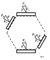
- the fourth and final embodiment relates to a hexagonal holding body, ie with sechcroftr rotational symmetry and six equal side walls.
- a hexagonal holding body ie with sechcroftr rotational symmetry and six equal side walls.
- the bending beam sensors are pairs in the same way, each pair occupies two opposite side walls of the holding body.
- Fig. 3 Dashed the cross section of the holding body, a first pair of similar bending beam (rectangles) in the 6 o'clock and 12 o'clock position, a second pair of similar bending beam in the 4 o'clock and 10 o'clock position and the externally acting disturbing forces analogous to Fig.
- the sensor pairs may differ from each other, and in particular have different materials, dimensions and in particular also resonance frequencies.
- Magnetic field measuring devices in this construction are similar to the known ME sensor arrays, which can be used, inter alia, to sensitively detect temporally periodic magnetic fields with a complex or variable frequency spectrum.
- the inventive feature here is that the holding body has a 2N-count rotational symmetry with respect to an axis of symmetry, and M pairs of similar bending beam sensors arranged with their long axes parallel to the symmetry axis and connected to the holding body, that the magnetic field measuring device with respect to the symmetry axis a twofold rotational symmetry where N and M are natural numbers.
- a rotational symmetry of the magnetic field measuring device is the speech, which not only describes the holding body and the geometric arrangement of the bending beam on the holding body, but also includes the orientation of the bending beam with respect to the axis of rotation.
- the undersides of the bending beam in the arrangement may optionally be facing the axis of rotation or facing away, but always so that similar Bending beam are symmetrically oriented and - if necessary, at least in pairs - bend in the presence of a detectable magnetic field synchronously on the axis of rotation to or away from it.
- the mechanical coupling of the bending beams introduced via the holding body makes it possible to maintain the symmetrical mechanical conditions, as long as the magnetic field measuring device performs a vibration only on the basis of a temporally periodic magnetic field.
- each bending bar detects a portion of the disturbance and outputs a disturbed voltage signal.
- the interference components cancel each other out in the sum of the signals with similar bending beams. If not all the bending beams used are similar, as in the last two embodiments, then it may be appropriate to weight the voltage signals of different bending beam pairs differently in the summation. Therefore, the generalization of the formation of a linear combination of all voltage signals of the bending beam as output of the magnetic field measuring device according to the invention is discussed here.
- the device is to be connected to at least one attachment point with a suitable tripod for fixing the position.
- the tripod can be a linkage or the housing of a measuring chamber, in any case, the tripod is a conductor for structure-borne noise.
- the attachment point of the magnetic field measuring device becomes the entry point for structure-borne noise into the sensor through the connection with the stand itself. It is particularly advantageous to choose this attachment point as close as possible to a force node and, moreover, the transmission of structure-borne noise from the stand by providing a sound-damping connection, e.g. by elastic gripper pillows in a clamping connection to suppress.
Landscapes
- Physics & Mathematics (AREA)
- Condensed Matter Physics & Semiconductors (AREA)
- General Physics & Mathematics (AREA)
- Engineering & Computer Science (AREA)
- Health & Medical Sciences (AREA)
- Environmental & Geological Engineering (AREA)
- Toxicology (AREA)
- Chemical & Material Sciences (AREA)
- Analytical Chemistry (AREA)
- Computer Hardware Design (AREA)
- Microelectronics & Electronic Packaging (AREA)
- Measuring Magnetic Variables (AREA)
Priority Applications (3)
| Application Number | Priority Date | Filing Date | Title |
|---|---|---|---|
| EP13170893.5A EP2811314B1 (fr) | 2013-06-06 | 2013-06-06 | Dispositif de mesure du champ magnétique avec compensation des vibrations |
| US14/894,407 US9810749B2 (en) | 2013-06-06 | 2014-05-27 | Magnetic field measuring device with vibration compensation |
| PCT/DE2014/100181 WO2014194887A1 (fr) | 2013-06-06 | 2014-05-27 | Dispositif de mesure de champ magnétique à compensation de vibrations |
Applications Claiming Priority (1)
| Application Number | Priority Date | Filing Date | Title |
|---|---|---|---|
| EP13170893.5A EP2811314B1 (fr) | 2013-06-06 | 2013-06-06 | Dispositif de mesure du champ magnétique avec compensation des vibrations |
Publications (2)
| Publication Number | Publication Date |
|---|---|
| EP2811314A1 true EP2811314A1 (fr) | 2014-12-10 |
| EP2811314B1 EP2811314B1 (fr) | 2016-09-07 |
Family
ID=48539060
Family Applications (1)
| Application Number | Title | Priority Date | Filing Date |
|---|---|---|---|
| EP13170893.5A Not-in-force EP2811314B1 (fr) | 2013-06-06 | 2013-06-06 | Dispositif de mesure du champ magnétique avec compensation des vibrations |
Country Status (3)
| Country | Link |
|---|---|
| US (1) | US9810749B2 (fr) |
| EP (1) | EP2811314B1 (fr) |
| WO (1) | WO2014194887A1 (fr) |
Families Citing this family (5)
| Publication number | Priority date | Publication date | Assignee | Title |
|---|---|---|---|---|
| US10312429B2 (en) * | 2016-07-28 | 2019-06-04 | Eyob Llc | Magnetoelectric macro fiber composite fabricated using low temperature transient liquid phase bonding |
| RU188677U1 (ru) * | 2019-02-08 | 2019-04-22 | Федеральное государственное автономное образовательное учреждение высшего образования "Национальный исследовательский технологический университет "МИСиС" | Магнитоэлектрический сенсор магнитных полей |
| JP7040503B2 (ja) * | 2019-08-27 | 2022-03-23 | 横河電機株式会社 | 電流測定装置 |
| CN110794345A (zh) * | 2019-11-07 | 2020-02-14 | 青岛大学 | 一种fm/fe/fm多铁异质结及磁电耦合传感器 |
| CN113639732A (zh) * | 2021-06-29 | 2021-11-12 | 西安交通大学 | 一种基于层状磁电复合材料的磁电罗盘及其应用 |
Family Cites Families (4)
| Publication number | Priority date | Publication date | Assignee | Title |
|---|---|---|---|---|
| US20090062886A1 (en) * | 2002-12-09 | 2009-03-05 | Ferro Solutions, Inc. | Systems and methods for delivering electrical energy in the body |
| US7830142B2 (en) | 2006-06-26 | 2010-11-09 | Alcatel-Lucent Usa Inc. | Tuning fork magnetometer |
| US7923999B2 (en) * | 2008-08-14 | 2011-04-12 | The United States Of America As Represented By The Secretary Of The Army | MEMS device with supplemental flux concentrator |
| CN102519633B (zh) * | 2011-11-30 | 2014-07-16 | 浙江大学 | 磁弹磁电效应式应力监测装置 |
-
2013
- 2013-06-06 EP EP13170893.5A patent/EP2811314B1/fr not_active Not-in-force
-
2014
- 2014-05-27 WO PCT/DE2014/100181 patent/WO2014194887A1/fr not_active Ceased
- 2014-05-27 US US14/894,407 patent/US9810749B2/en not_active Expired - Fee Related
Non-Patent Citations (2)
| Title |
|---|
| STEPHAN MARAUSKA ET AL: "Paper;MEMS magnetic field sensor based on magnetoelectric composites;MEMS magnetic field sensor based on magnetoelectric composites", JOURNAL OF MICROMECHANICS & MICROENGINEERING, INSTITUTE OF PHYSICS PUBLISHING, BRISTOL, GB, vol. 22, no. 6, 22 May 2012 (2012-05-22), pages 65024, XP020224204, ISSN: 0960-1317, DOI: 10.1088/0960-1317/22/6/065024 * |
| XING ZENGPING ET AL: "Investigation of external noise and its rejection in magnetoelectric sensor design", JOURNAL OF APPLIED PHYSICS, AMERICAN INSTITUTE OF PHYSICS. NEW YORK, US, vol. 106, no. 2, 28 July 2009 (2009-07-28), pages 24512 - 24512, XP012123655, ISSN: 0021-8979, DOI: 10.1063/1.3176500 * |
Also Published As
| Publication number | Publication date |
|---|---|
| US20160116552A1 (en) | 2016-04-28 |
| EP2811314B1 (fr) | 2016-09-07 |
| WO2014194887A1 (fr) | 2014-12-11 |
| US9810749B2 (en) | 2017-11-07 |
Similar Documents
| Publication | Publication Date | Title |
|---|---|---|
| DE69105773T2 (de) | Magnetostriktiver Antrieb. | |
| DE4432747C2 (de) | Vorrichtung und Verfahren zur Geräuschdämpfung in einem Kernspintomographen | |
| DE2505461C2 (de) | Meßumformer zum Bestimmen einer ein Substrat verformenden Meßgröße | |
| EP2811314B1 (fr) | Dispositif de mesure du champ magnétique avec compensation des vibrations | |
| AT507303B1 (de) | Sensor zum messen mechanischer spannungen | |
| DE3502008A1 (de) | Dehnungsaufnehmer | |
| DE19827056A1 (de) | Mikromechanischer Magnetfeldsensor | |
| DE102015114406A1 (de) | System zur drahtlosen Übertragung von Energie und/oder Signalen, der Wandlung der Energie und/oder Signale in andere Energieformen und/oder Signalformen sowie deren Applizierung und Detektion in peripheren Bereichen des Systems | |
| DE4327052C2 (de) | Massendurchflußmeßgerät | |
| DE202005021706U1 (de) | Sensorelement mit zumindest einem Messelement, welches piezoelektrische und pyroelektrische Eigenschaften aufweist | |
| DE4137167A1 (de) | Mikromechanischer sensor | |
| DE102016123274A1 (de) | Sensorelement für Magnetfelder mit hoher Frequenzbandbreite | |
| DE1773491C3 (de) | Druckempfindliche Vorrichtung mit einer elastischen Membran | |
| DE102021109408A1 (de) | Magnetfeldsensor und Sensoranordnung | |
| DE69018453T2 (de) | Piezoelektrischer differenzdrucksensor für einen wirbeldurchflussmesser. | |
| EP3987300B1 (fr) | Dispositif de mesure pour des champs magnétiques faibles, lentement variables, en particulier pour des champs biomagnétiques | |
| DE2425177C3 (de) | Druckmeßwertgeber | |
| DE102013103445A1 (de) | Magnetischer Linear- oder Drehgeber | |
| CH536362A (de) | Metall- oder Halbleiterlegierung mit kleinen Temperaturkoeffizienten der Elastizität | |
| DE102020130558A1 (de) | Antrieb für einen Vibrationssensor, Vibrationssensor und Verwendung von Formgedächtnismaterialien als Antriebselement in Vibrationssensoren sowie Verfahren zum Antrieb eines Vibrationssensors | |
| DE1957586A1 (de) | Kraftumformer | |
| DE102015113244A1 (de) | Aktoranordnung mit magnetischer Formgedächtnislegierung | |
| DE102012112862B4 (de) | Vorrichtung zur Messung eines Druckes mit wenigstens einem Drucksensor mit wenigstens einer aktiven Sensorfläche | |
| EP3060933B1 (fr) | Magnétomètre à gradients, et procédé de détermination d'un composant individuel d'un capteur à gradients d'un champ magnétique | |
| WO2024199818A1 (fr) | Ensemble de compensation de la température d'un premier composant d'une première pièce |
Legal Events
| Date | Code | Title | Description |
|---|---|---|---|
| PUAI | Public reference made under article 153(3) epc to a published international application that has entered the european phase |
Free format text: ORIGINAL CODE: 0009012 |
|
| 17P | Request for examination filed |
Effective date: 20130606 |
|
| AK | Designated contracting states |
Kind code of ref document: A1 Designated state(s): AL AT BE BG CH CY CZ DE DK EE ES FI FR GB GR HR HU IE IS IT LI LT LU LV MC MK MT NL NO PL PT RO RS SE SI SK SM TR |
|
| AX | Request for extension of the european patent |
Extension state: BA ME |
|
| R17P | Request for examination filed (corrected) |
Effective date: 20150115 |
|
| RBV | Designated contracting states (corrected) |
Designated state(s): AL AT BE BG CH CY CZ DE DK EE ES FI FR GB GR HR HU IE IS IT LI LT LU LV MC MK MT NL NO PL PT RO RS SE SI SK SM TR |
|
| GRAP | Despatch of communication of intention to grant a patent |
Free format text: ORIGINAL CODE: EPIDOSNIGR1 |
|
| RIC1 | Information provided on ipc code assigned before grant |
Ipc: G01R 33/00 20060101ALI20160308BHEP Ipc: G01R 33/06 20060101AFI20160308BHEP Ipc: G01R 33/18 20060101ALI20160308BHEP |
|
| INTG | Intention to grant announced |
Effective date: 20160408 |
|
| GRAS | Grant fee paid |
Free format text: ORIGINAL CODE: EPIDOSNIGR3 |
|
| GRAA | (expected) grant |
Free format text: ORIGINAL CODE: 0009210 |
|
| AK | Designated contracting states |
Kind code of ref document: B1 Designated state(s): AL AT BE BG CH CY CZ DE DK EE ES FI FR GB GR HR HU IE IS IT LI LT LU LV MC MK MT NL NO PL PT RO RS SE SI SK SM TR |
|
| REG | Reference to a national code |
Ref country code: GB Ref legal event code: FG4D Free format text: NOT ENGLISH |
|
| REG | Reference to a national code |
Ref country code: CH Ref legal event code: EP |
|
| REG | Reference to a national code |
Ref country code: IE Ref legal event code: FG4D Free format text: LANGUAGE OF EP DOCUMENT: GERMAN |
|
| REG | Reference to a national code |
Ref country code: AT Ref legal event code: REF Ref document number: 827333 Country of ref document: AT Kind code of ref document: T Effective date: 20161015 |
|
| REG | Reference to a national code |
Ref country code: DE Ref legal event code: R096 Ref document number: 502013004330 Country of ref document: DE |
|
| REG | Reference to a national code |
Ref country code: NL Ref legal event code: FP |
|
| REG | Reference to a national code |
Ref country code: LT Ref legal event code: MG4D |
|
| PG25 | Lapsed in a contracting state [announced via postgrant information from national office to epo] |
Ref country code: RS Free format text: LAPSE BECAUSE OF FAILURE TO SUBMIT A TRANSLATION OF THE DESCRIPTION OR TO PAY THE FEE WITHIN THE PRESCRIBED TIME-LIMIT Effective date: 20160907 Ref country code: FI Free format text: LAPSE BECAUSE OF FAILURE TO SUBMIT A TRANSLATION OF THE DESCRIPTION OR TO PAY THE FEE WITHIN THE PRESCRIBED TIME-LIMIT Effective date: 20160907 Ref country code: NO Free format text: LAPSE BECAUSE OF FAILURE TO SUBMIT A TRANSLATION OF THE DESCRIPTION OR TO PAY THE FEE WITHIN THE PRESCRIBED TIME-LIMIT Effective date: 20161207 Ref country code: LT Free format text: LAPSE BECAUSE OF FAILURE TO SUBMIT A TRANSLATION OF THE DESCRIPTION OR TO PAY THE FEE WITHIN THE PRESCRIBED TIME-LIMIT Effective date: 20160907 Ref country code: HR Free format text: LAPSE BECAUSE OF FAILURE TO SUBMIT A TRANSLATION OF THE DESCRIPTION OR TO PAY THE FEE WITHIN THE PRESCRIBED TIME-LIMIT Effective date: 20160907 |
|
| PG25 | Lapsed in a contracting state [announced via postgrant information from national office to epo] |
Ref country code: SE Free format text: LAPSE BECAUSE OF FAILURE TO SUBMIT A TRANSLATION OF THE DESCRIPTION OR TO PAY THE FEE WITHIN THE PRESCRIBED TIME-LIMIT Effective date: 20160907 Ref country code: GR Free format text: LAPSE BECAUSE OF FAILURE TO SUBMIT A TRANSLATION OF THE DESCRIPTION OR TO PAY THE FEE WITHIN THE PRESCRIBED TIME-LIMIT Effective date: 20161208 Ref country code: LV Free format text: LAPSE BECAUSE OF FAILURE TO SUBMIT A TRANSLATION OF THE DESCRIPTION OR TO PAY THE FEE WITHIN THE PRESCRIBED TIME-LIMIT Effective date: 20160907 Ref country code: ES Free format text: LAPSE BECAUSE OF FAILURE TO SUBMIT A TRANSLATION OF THE DESCRIPTION OR TO PAY THE FEE WITHIN THE PRESCRIBED TIME-LIMIT Effective date: 20160907 |
|
| PG25 | Lapsed in a contracting state [announced via postgrant information from national office to epo] |
Ref country code: EE Free format text: LAPSE BECAUSE OF FAILURE TO SUBMIT A TRANSLATION OF THE DESCRIPTION OR TO PAY THE FEE WITHIN THE PRESCRIBED TIME-LIMIT Effective date: 20160907 Ref country code: RO Free format text: LAPSE BECAUSE OF FAILURE TO SUBMIT A TRANSLATION OF THE DESCRIPTION OR TO PAY THE FEE WITHIN THE PRESCRIBED TIME-LIMIT Effective date: 20160907 |
|
| PG25 | Lapsed in a contracting state [announced via postgrant information from national office to epo] |
Ref country code: PT Free format text: LAPSE BECAUSE OF FAILURE TO SUBMIT A TRANSLATION OF THE DESCRIPTION OR TO PAY THE FEE WITHIN THE PRESCRIBED TIME-LIMIT Effective date: 20170109 Ref country code: BG Free format text: LAPSE BECAUSE OF FAILURE TO SUBMIT A TRANSLATION OF THE DESCRIPTION OR TO PAY THE FEE WITHIN THE PRESCRIBED TIME-LIMIT Effective date: 20161207 Ref country code: CZ Free format text: LAPSE BECAUSE OF FAILURE TO SUBMIT A TRANSLATION OF THE DESCRIPTION OR TO PAY THE FEE WITHIN THE PRESCRIBED TIME-LIMIT Effective date: 20160907 Ref country code: SK Free format text: LAPSE BECAUSE OF FAILURE TO SUBMIT A TRANSLATION OF THE DESCRIPTION OR TO PAY THE FEE WITHIN THE PRESCRIBED TIME-LIMIT Effective date: 20160907 Ref country code: IS Free format text: LAPSE BECAUSE OF FAILURE TO SUBMIT A TRANSLATION OF THE DESCRIPTION OR TO PAY THE FEE WITHIN THE PRESCRIBED TIME-LIMIT Effective date: 20170107 Ref country code: SM Free format text: LAPSE BECAUSE OF FAILURE TO SUBMIT A TRANSLATION OF THE DESCRIPTION OR TO PAY THE FEE WITHIN THE PRESCRIBED TIME-LIMIT Effective date: 20160907 Ref country code: PL Free format text: LAPSE BECAUSE OF FAILURE TO SUBMIT A TRANSLATION OF THE DESCRIPTION OR TO PAY THE FEE WITHIN THE PRESCRIBED TIME-LIMIT Effective date: 20160907 |
|
| REG | Reference to a national code |
Ref country code: DE Ref legal event code: R097 Ref document number: 502013004330 Country of ref document: DE |
|
| REG | Reference to a national code |
Ref country code: FR Ref legal event code: PLFP Year of fee payment: 5 |
|
| PG25 | Lapsed in a contracting state [announced via postgrant information from national office to epo] |
Ref country code: IT Free format text: LAPSE BECAUSE OF FAILURE TO SUBMIT A TRANSLATION OF THE DESCRIPTION OR TO PAY THE FEE WITHIN THE PRESCRIBED TIME-LIMIT Effective date: 20160907 |
|
| PLBE | No opposition filed within time limit |
Free format text: ORIGINAL CODE: 0009261 |
|
| STAA | Information on the status of an ep patent application or granted ep patent |
Free format text: STATUS: NO OPPOSITION FILED WITHIN TIME LIMIT |
|
| PG25 | Lapsed in a contracting state [announced via postgrant information from national office to epo] |
Ref country code: DK Free format text: LAPSE BECAUSE OF FAILURE TO SUBMIT A TRANSLATION OF THE DESCRIPTION OR TO PAY THE FEE WITHIN THE PRESCRIBED TIME-LIMIT Effective date: 20160907 |
|
| 26N | No opposition filed |
Effective date: 20170608 |
|
| PG25 | Lapsed in a contracting state [announced via postgrant information from national office to epo] |
Ref country code: SI Free format text: LAPSE BECAUSE OF FAILURE TO SUBMIT A TRANSLATION OF THE DESCRIPTION OR TO PAY THE FEE WITHIN THE PRESCRIBED TIME-LIMIT Effective date: 20160907 |
|
| PG25 | Lapsed in a contracting state [announced via postgrant information from national office to epo] |
Ref country code: MC Free format text: LAPSE BECAUSE OF FAILURE TO SUBMIT A TRANSLATION OF THE DESCRIPTION OR TO PAY THE FEE WITHIN THE PRESCRIBED TIME-LIMIT Effective date: 20160907 |
|
| REG | Reference to a national code |
Ref country code: CH Ref legal event code: PL |
|
| REG | Reference to a national code |
Ref country code: IE Ref legal event code: MM4A |
|
| PG25 | Lapsed in a contracting state [announced via postgrant information from national office to epo] |
Ref country code: CH Free format text: LAPSE BECAUSE OF NON-PAYMENT OF DUE FEES Effective date: 20170630 Ref country code: LU Free format text: LAPSE BECAUSE OF NON-PAYMENT OF DUE FEES Effective date: 20170606 Ref country code: LI Free format text: LAPSE BECAUSE OF NON-PAYMENT OF DUE FEES Effective date: 20170630 Ref country code: IE Free format text: LAPSE BECAUSE OF NON-PAYMENT OF DUE FEES Effective date: 20170606 |
|
| REG | Reference to a national code |
Ref country code: BE Ref legal event code: MM Effective date: 20170630 |
|
| REG | Reference to a national code |
Ref country code: FR Ref legal event code: PLFP Year of fee payment: 6 |
|
| PG25 | Lapsed in a contracting state [announced via postgrant information from national office to epo] |
Ref country code: BE Free format text: LAPSE BECAUSE OF NON-PAYMENT OF DUE FEES Effective date: 20170630 |
|
| PG25 | Lapsed in a contracting state [announced via postgrant information from national office to epo] |
Ref country code: MT Free format text: LAPSE BECAUSE OF FAILURE TO SUBMIT A TRANSLATION OF THE DESCRIPTION OR TO PAY THE FEE WITHIN THE PRESCRIBED TIME-LIMIT Effective date: 20160907 |
|
| PG25 | Lapsed in a contracting state [announced via postgrant information from national office to epo] |
Ref country code: AL Free format text: LAPSE BECAUSE OF FAILURE TO SUBMIT A TRANSLATION OF THE DESCRIPTION OR TO PAY THE FEE WITHIN THE PRESCRIBED TIME-LIMIT Effective date: 20160907 |
|
| PG25 | Lapsed in a contracting state [announced via postgrant information from national office to epo] |
Ref country code: HU Free format text: LAPSE BECAUSE OF FAILURE TO SUBMIT A TRANSLATION OF THE DESCRIPTION OR TO PAY THE FEE WITHIN THE PRESCRIBED TIME-LIMIT; INVALID AB INITIO Effective date: 20130606 |
|
| REG | Reference to a national code |
Ref country code: AT Ref legal event code: MM01 Ref document number: 827333 Country of ref document: AT Kind code of ref document: T Effective date: 20180606 |
|
| PG25 | Lapsed in a contracting state [announced via postgrant information from national office to epo] |
Ref country code: CY Free format text: LAPSE BECAUSE OF FAILURE TO SUBMIT A TRANSLATION OF THE DESCRIPTION OR TO PAY THE FEE WITHIN THE PRESCRIBED TIME-LIMIT Effective date: 20160907 |
|
| PG25 | Lapsed in a contracting state [announced via postgrant information from national office to epo] |
Ref country code: MK Free format text: LAPSE BECAUSE OF FAILURE TO SUBMIT A TRANSLATION OF THE DESCRIPTION OR TO PAY THE FEE WITHIN THE PRESCRIBED TIME-LIMIT Effective date: 20160907 |
|
| PG25 | Lapsed in a contracting state [announced via postgrant information from national office to epo] |
Ref country code: AT Free format text: LAPSE BECAUSE OF NON-PAYMENT OF DUE FEES Effective date: 20180606 |
|
| PG25 | Lapsed in a contracting state [announced via postgrant information from national office to epo] |
Ref country code: TR Free format text: LAPSE BECAUSE OF FAILURE TO SUBMIT A TRANSLATION OF THE DESCRIPTION OR TO PAY THE FEE WITHIN THE PRESCRIBED TIME-LIMIT Effective date: 20160907 |
|
| REG | Reference to a national code |
Ref country code: DE Ref legal event code: R082 Ref document number: 502013004330 Country of ref document: DE Representative=s name: HEESCHEN, SVEN, DIPL.-PHYS., DE |
|
| PGFP | Annual fee paid to national office [announced via postgrant information from national office to epo] |
Ref country code: NL Payment date: 20230620 Year of fee payment: 11 Ref country code: FR Payment date: 20230621 Year of fee payment: 11 Ref country code: DE Payment date: 20230620 Year of fee payment: 11 |
|
| PGFP | Annual fee paid to national office [announced via postgrant information from national office to epo] |
Ref country code: GB Payment date: 20230622 Year of fee payment: 11 |
|
| REG | Reference to a national code |
Ref country code: DE Ref legal event code: R119 Ref document number: 502013004330 Country of ref document: DE |
|
| REG | Reference to a national code |
Ref country code: NL Ref legal event code: MM Effective date: 20240701 |
|
| GBPC | Gb: european patent ceased through non-payment of renewal fee |
Effective date: 20240606 |
|
| PG25 | Lapsed in a contracting state [announced via postgrant information from national office to epo] |
Ref country code: NL Free format text: LAPSE BECAUSE OF NON-PAYMENT OF DUE FEES Effective date: 20240701 |
|
| PG25 | Lapsed in a contracting state [announced via postgrant information from national office to epo] |
Ref country code: NL Free format text: LAPSE BECAUSE OF NON-PAYMENT OF DUE FEES Effective date: 20240701 |
|
| PG25 | Lapsed in a contracting state [announced via postgrant information from national office to epo] |
Ref country code: DE Free format text: LAPSE BECAUSE OF NON-PAYMENT OF DUE FEES Effective date: 20250101 |
|
| PG25 | Lapsed in a contracting state [announced via postgrant information from national office to epo] |
Ref country code: FR Free format text: LAPSE BECAUSE OF NON-PAYMENT OF DUE FEES Effective date: 20240630 |
|
| PG25 | Lapsed in a contracting state [announced via postgrant information from national office to epo] |
Ref country code: GB Free format text: LAPSE BECAUSE OF NON-PAYMENT OF DUE FEES Effective date: 20240606 |