EP2811358B1 - Annäherungsverfahren einer Plattform - Google Patents
Annäherungsverfahren einer Plattform Download PDFInfo
- Publication number
- EP2811358B1 EP2811358B1 EP14001499.4A EP14001499A EP2811358B1 EP 2811358 B1 EP2811358 B1 EP 2811358B1 EP 14001499 A EP14001499 A EP 14001499A EP 2811358 B1 EP2811358 B1 EP 2811358B1
- Authority
- EP
- European Patent Office
- Prior art keywords
- approach
- aircraft
- intruder
- situated
- current position
- Prior art date
- Legal status (The legal status is an assumption and is not a legal conclusion. Google has not performed a legal analysis and makes no representation as to the accuracy of the status listed.)
- Active
Links
Images

Classifications
-
- G—PHYSICS
- G01—MEASURING; TESTING
- G01C—MEASURING DISTANCES, LEVELS OR BEARINGS; SURVEYING; NAVIGATION; GYROSCOPIC INSTRUMENTS; PHOTOGRAMMETRY OR VIDEOGRAMMETRY
- G01C23/00—Combined instruments indicating more than one navigational value, e.g. for aircraft; Combined measuring devices for measuring two or more variables of movement, e.g. distance, speed or acceleration
- G01C23/005—Flight directors
-
- G—PHYSICS
- G01—MEASURING; TESTING
- G01C—MEASURING DISTANCES, LEVELS OR BEARINGS; SURVEYING; NAVIGATION; GYROSCOPIC INSTRUMENTS; PHOTOGRAMMETRY OR VIDEOGRAMMETRY
- G01C21/00—Navigation; Navigational instruments not provided for in groups G01C1/00 - G01C19/00
- G01C21/20—Instruments for performing navigational calculations
-
- G—PHYSICS
- G01—MEASURING; TESTING
- G01S—RADIO DIRECTION-FINDING; RADIO NAVIGATION; DETERMINING DISTANCE OR VELOCITY BY USE OF RADIO WAVES; LOCATING OR PRESENCE-DETECTING BY USE OF THE REFLECTION OR RERADIATION OF RADIO WAVES; ANALOGOUS ARRANGEMENTS USING OTHER WAVES
- G01S13/00—Systems using the reflection or reradiation of radio waves, e.g. radar systems; Analogous systems using reflection or reradiation of waves whose nature or wavelength is irrelevant or unspecified
- G01S13/88—Radar or analogous systems specially adapted for specific applications
- G01S13/91—Radar or analogous systems specially adapted for specific applications for traffic control
- G01S13/913—Radar or analogous systems specially adapted for specific applications for traffic control for landing purposes
-
- G—PHYSICS
- G01—MEASURING; TESTING
- G01S—RADIO DIRECTION-FINDING; RADIO NAVIGATION; DETERMINING DISTANCE OR VELOCITY BY USE OF RADIO WAVES; LOCATING OR PRESENCE-DETECTING BY USE OF THE REFLECTION OR RERADIATION OF RADIO WAVES; ANALOGOUS ARRANGEMENTS USING OTHER WAVES
- G01S13/00—Systems using the reflection or reradiation of radio waves, e.g. radar systems; Analogous systems using reflection or reradiation of waves whose nature or wavelength is irrelevant or unspecified
- G01S13/88—Radar or analogous systems specially adapted for specific applications
- G01S13/93—Radar or analogous systems specially adapted for specific applications for anti-collision purposes
- G01S13/933—Radar or analogous systems specially adapted for specific applications for anti-collision purposes of aircraft or spacecraft
-
- G—PHYSICS
- G05—CONTROLLING; REGULATING
- G05D—SYSTEMS FOR CONTROLLING OR REGULATING NON-ELECTRIC VARIABLES
- G05D1/00—Control of position, course, altitude or attitude of land, water, air or space vehicles, e.g. using automatic pilots
- G05D1/04—Control of altitude or depth
- G05D1/06—Rate of change of altitude or depth
- G05D1/0607—Rate of change of altitude or depth specially adapted for aircraft
- G05D1/0653—Rate of change of altitude or depth specially adapted for aircraft during a phase of take-off or landing
- G05D1/0676—Rate of change of altitude or depth specially adapted for aircraft during a phase of take-off or landing specially adapted for landing
-
- G—PHYSICS
- G08—SIGNALLING
- G08G—TRAFFIC CONTROL SYSTEMS
- G08G5/00—Traffic control systems for aircraft
- G08G5/50—Navigation or guidance aids
- G08G5/54—Navigation or guidance aids for approach or landing
Definitions
- the present invention relates to a method for driving an aircraft on a platform, and in particular a short landing aircraft such as an aircraft equipped with a rotary wing for example.
- the invention is therefore in the technical field of aircraft piloting assistance systems, including automated systems for assisting the approach of platforms for rotorcraft.
- a rotary wing aircraft must be able to find and approach safely mobile platforms or vessels, regardless of weather conditions and visibility and avoiding obstacles in the approach area.
- the approach is conducted taking into account the direction and speed of the wind in the sector, the type of platform to approach (fixed platforms, mobile, boats or barges), surrounding obstacles (cranes, barges, boats used for positioning platform, container-type boats or “super tanker” sailing around the approach zone, or other surrounding platforms), passenger comfort.
- the type of platform to approach fixed platforms, mobile, boats or barges
- surrounding obstacles cranes, barges, boats used for positioning platform, container-type boats or "super tanker” sailing around the approach zone, or other surrounding platforms
- passenger comfort is conducted taking into account the direction and speed of the wind in the sector, the type of platform to approach (fixed platforms, mobile, boats or barges), surrounding obstacles (cranes, barges, boats used for positioning platform, container-type boats or “super tanker” sailing around the approach zone, or other surrounding platforms), passenger comfort.
- the approach includes an arrival segment that connects the last flight point of the current flight phase and an initial approach point known as "IAF” or "Initial Approach Fix” in English.
- This arrival segment is generally positioned at an altitude of 1500 ft. It is recalled that the symbol “ft” refers to the unit of length called “feet” in the English language, equal to 30.48 centimeters.
- An initial approach segment may link the initial approach point IAF to an intermediate point known as IF, or Intermediate Fix in the English language. This initial approach segment aims to allow the aircraft to decelerate and align with the trajectory to follow.
- An intermediate approach segment may connect the intermediate point IF to a final approach point known as "FAF” or "Final Approach Fix” in English to descend to an altitude of up to 1000 ft. This segment aims to align the aircraft, decelerate and prepare the final approach segment.
- FAF Final Approach Fix
- At least one final approach segment connects the FAF final approach point and a decision point known as "MAP” or "Missed Approach point” in English.
- the final approach point FAF is connected to the decision point MAP via an LPO bearing point and an OIP offset point.
- the pilot can land the aircraft on that platform.
- a so-called go-around segment must be conducted if visual contact with the platform is not obtained at this stage of the approach.
- This go-around segment may also be conducted at any point in the approach if the crew deems it useful.
- the purpose of this go-around segment is to reach a safe altitude.
- nm refers to the unit of length denominated "nautical mile” in the English language worth 1852 meters.
- the approach procedure may be canceled for safety reasons. Detecting such obstacles can be tricky. Indeed, a crew may have difficulty assessing whether the presence of a moving ship is likely to terminate the approach procedure.
- NDB Non Directional Beacon
- a navigation computer used to provide horizontal guidance during the en-route phase is known.
- the crew determines an off-road target point corresponding to the coordinates of the platform to be reached as a means of assisting navigation.
- the navigation computer does not segment the different phases of approach to the platform to slave the autopilot on these guidance data (horizontal deflection, vertical deviation, speed reference).
- the approach is then conducted manually or semi-automatically via the assistance of some higher modes of the autopilot using the approach charts published by the operators and approved by the local authorities.
- the weather radar of the aircraft can also be used as a means of identification of the platform, detection and transient or fixed obstacle avoidance during the approach and the final descent.
- the document US 2010/0168939 proposes a module and an automated method for approaching a platform on an approach trajectory constructed from approach points.
- the aircraft module determines in particular the position of the initial approach point IAF and the final approach point FAF in response to the data entered. The aircraft is then directed to the initial point of approach.
- the constructed approach path comprises a horizontal segment connecting an initial approach point IAF to a final approach point FAF.
- the path includes a descent segment and then a level segment to connect the final approach point FAF to a decision point MAP.
- the initial approach point IAF, the final approach point FAF and the decision point MAP are contained in a vertical plane parallel to the chosen approach heading. It is understood that the term "vertical plane" a plane directed according to gravity, points of this vertical plane may be at different altitudes.
- This vertical plane is offset from the platform by a distance equal to the offset distance entered.
- the document US7016772 B2 unveils an information display device on vehicles according to their importance (size, position, speed), and unveils a ship system that combines radar information with information from an automatic identification system known as 'acronym' AIS 'means' Automatic Identification System' in the English language.
- the document US8296001 B1 unveils a system that assists a navigator by giving the characteristics of other boats and coastal information.
- a radar or AIS system can be used.
- the document JP3763004 B1 describes a system for protecting a descent plane when approaching aircraft to an airport vis-à-vis ships using an AIS system.
- the present invention therefore aims to provide an approach method for helping a crew to land on a platform with an aircraft.
- a method for facilitating the approach of a platform present on a liquid surface with an aircraft comprises a development phase to develop an approach path to a theoretical position of said platform.
- this method comprises a consolidation phase and may include a security phase.
- the monitored objects can be floating objects and / or flying objects.
- the development phase can be undertaken automatically by a navigation computer, from input data including the theoretical position of the platform and an approach course such as a course to follow, for example.
- input data including the theoretical position of the platform and an approach course such as a course to follow, for example.
- approach course such as a course to follow, for example.
- the theoretical position can be entered by an operator, or it can come from a platform database.
- This database comprises, for example, an identifier of the platform and these coordinates. Other information may be present, such as a radius of each platform including considering that each platform is contained in a circle.
- the consolidation phase proposes to compare the theoretical position of a target platform that made it possible to establish the approach trajectory at a current position of this target platform.
- a radar signal or a signal known by the acronym AIS referring to an automatic identification system makes it possible to obtain a "measured" current position of the target platform.
- the first threshold may be of the order of 0.1 Nm.
- the aircraft performs measurements at a given frequency.
- the aircraft may report positions transmitted by automatic identification systems every 6 seconds during a forward flight.
- an alert can be generated only if a plurality of measurements confirms the offset present between the theoretical position and the measured current position.
- the consolidation phase can be performed automatically and in real time by a computer, such as a map calculator known by the acronym DMAP communicating with the navigation computer.
- a computer such as a map calculator known by the acronym DMAP communicating with the navigation computer.
- this method can implement a security phase.
- Certain regulations require the aircraft to follow an approach path present in a 2 nm wide approach corridor centered on this approach path, this approach corridor must not contain any obstacle.
- These automatic identification systems transmit information to the aircraft relating to the obstacle, such as its position and its speed vector.
- the dangerousness of the obstacle is determined by determining the risks of conflict between the trajectory of the aircraft and the trajectory of the obstacle. This operation is for example carried out for each obstacle present in the surveillance zone considered. Therefore, it is displayed on a display screen the approach path followed by the aircraft, as well as identifiers visually to determine the position of an obstacle, the movement performed by the obstacle, the dangerousness of the obstacle by relation to the calculated approach trajectory or even the predictive position of the obstacle at the end of a given time.
- an aircraft crew member can establish an alternative approach course if an obstacle is likely to be present in the current approach corridor.
- the aircraft can also divert if necessary.
- This method may further include one or more of the following additional features.
- the theoretical position of the platform can be manually modified.
- the second threshold may be greater than the first threshold.
- the theoretical position of the platform is modified to minimize the distance separating it from the current position taken up, making it coincide with the current position, if any.
- the new theoretical position is then used to establish the approach path, for example by a navigation calculator.
- This slider can point to the current position displayed on this display screen for example.
- the registration of the platform is allowed only if the determined distance is less than the second threshold, of the order of 0.3 nm for example. This feature aims to avoid a risky registration if there is too much difference between the theoretical position and the current position.
- the registration may be authorized independently of the value of this distance.
- This registration can induce an automatic calculation of a new approach trajectory.
- Re-registration may be prohibited if it occurs too late in the approach procedure.
- the manufacturer may determine an approach point from which registration is prohibited.
- the consolidation phase begins when the aircraft receives information from an automatic system for identifying the platform.
- the predetermined monitoring zone is optionally a circle of a radius defined by the manufacturer centered on the platform to be reached.
- This radius may correspond to the length separating an initial approach point IAF from the target platform plus a constant, of the order of 0.5 nm for example.
- an approach corridor of a given width centered on said approach path.
- the width may be 2 nm according to certain regulations.
- the approach corridor can then be the approach corridor described in these regulations, possibly prolonged locally for safety reasons.
- each representation corresponds to the color of the plot.
- a white colored stud may signal a non-dangerous object with the first level of danger
- a shaded or colored amber stud may indicate a potentially dangerous object with the second level of danger
- a red or black colored stud may indicate a dangerous object presenting the third level of dangerousness.
- an operator develops an alternative approach course by choosing a new approach course. If the approach path has a segment shifted to the right of the platform relative to an initial segment, the operator can also choose a shift to the left of this platform, and vice versa.
- the first developed approach course and the alternative approach course on the display screen can be displayed with separate representations to facilitate the development of the alternative approach course.
- the current approach path is displayed in solid lines, and the alternative approach path in dashed lines.
- the alternative approach corridor can also be displayed.
- the mobile box can provide information to a pilot about the upcoming situation in the short term.
- This warning information on the potential risk of interference between the trajectory of the aircraft and the path of the moving obstacle can take into account either the current speed of the aircraft or the speed instructions followed by default by the aircraft. aircraft along the predicted course of approach.
- each object is schematized on the display screen using the following visual identifiers: a plot, an indication of the direction of movement of the object and a representation relating to the level of danger of the object through staining of the plot, for example, or an indication of predictive position of the object at the end of a given time.
- This indication of the direction of movement may be an arrow whose length depends on the speed of movement of the object, the arrow may lead to a predictive position of the object at the end of a given time predetermined by the manufacturer.
- the aforementioned symbologies may comprise identifiers of another type, or may consist of modifying at least one of these identifiers.
- the first symbology may not modify said identifiers.
- the second symbology can make the arrow flash
- the third symbology can flash a pad
- the fourth symbology can flash the pad and the arrow representing an object.
- the figure 1 presents an aircraft 1 able to implement the method according to the invention.
- This aircraft can comprise a navigation calculator 2, such as a computer commonly known by the acronym "FMS” and the English expression “Flight Management System”.
- a navigation calculator 2 such as a computer commonly known by the acronym "FMS” and the English expression “Flight Management System”.
- This navigation calculator 2 can communicate with a database 3 listing platforms and certain characteristics of these platforms.
- the navigation computer is in communication with an automatic guidance device 10 capable of guiding the aircraft along an approach path developed by the navigation computer.
- This navigation calculator can generate an approach trajectory to reach a target and in particular a platform floating on a liquid surface, and can transmit instructions to the automatic guidance device so that the aircraft is guided on this approach path. .
- the aircraft 1 is provided with a cartographic calculator, such as a calculator known by the acronym "DMAP” or the English expression “Digital Map”.
- a cartographic calculator such as a calculator known by the acronym "DMAP” or the English expression “Digital Map”.
- the cartographic calculator 4 is connected to an automatic identification system 5 known by the acronym "AIS" or the English expression “Automatic Identification System”.
- the automatic identification system 5 can receive signals AIS from objects equipped with a similar system. These AIS signals can provide the current latitude and longitude of the object, its speed of movement, its direction of movement, its height, its draft ...
- the cartographic calculator 4 can be connected to an automatic identification system 5 known by the acronym "TCAS” or the English expression “Traffic Collision Avoidance System”.
- TCAS automatic identification system
- the automatic identification system can receive TCAS signals from other aircraft equipped with a similar system. These TCAS signals can provide the distance between the aircraft and the intruder aircraft, as well as the following information relating to the intruder aircraft: altitude, vertical speed, relative run, current latitude and longitude, and the movement speed.
- the aircraft may comprise an automatic identification system 5 using AIS technology and / or TCAS technology in particular.
- the cartographic calculator 4 can communicate with a radar system 6 so as to receive echoes from radars and commonly referred to as "radar echoes".
- the cartographic calculator 4 is able to generate displays presenting in particular the radar echoes received and the objects identified by the automatic identification system 5.
- the navigation computer 2 and the cartographic calculator 4 are in communication with a display device 7.
- the display device is provided with a display screen and 9 or equivalent buttons operable by an operator. With the aid of these buttons 9, an operator can transmit instructions or information to the navigation calculator 2 and to the cartographic calculator 4.
- the automatic identification systems can be interfaced directly with the navigation computer 2 or with the display device 7.
- buttons 9 manipulates the buttons 9 to allow the navigation computer to develop an approach path 25.
- the operator chooses the target platform to be reached among the platforms stored in the database 3, a race CRS1 to be followed to reach the target platform, a height value relative to a minimum decision altitude for descent into final approach to said target platform such as a minimum descent altitude (MDA) to be reached for a landing following the final descent phase, an offset side to determine where the platform 20 should be in relation to the aircraft at a decision point MAP.
- MDA minimum descent altitude
- the navigation calculator then develops an approach path 25 to follow to reach the target platform according to the attributes of the platform present in the database 3, and parameterized information.
- This approach path 25 is displayed on the display screen in addition to the information displayed following the instructions of the cartographic calculator.
- the approach path may include an initial approach point IAF, a final approach point FAF, an offset point OIP and a decision point MAP based on said information and said attributes.
- an intermediate approach point IF and a bearing point LPO are also determined.
- the initial approach point IAF, the final approach point FAF, the OIP offset point, the coordinates of the target platform, and if appropriate the intermediate approach point IF and the bearing point LPO are arranged in a same vertical plane. This vertical plane is directed according to the set CRS1 race.
- the decision point MAP is shifted with respect to this vertical plane. It is recalled that the shift to the left or right of the decision point relative to the vertical plane is optionally configurable.
- the MAP decision point, the OIP offset point, and if necessary the LPO bearing point are arranged at an altitude equal to the MDA decision minimum altitude.
- the cartographic calculator can then implement a consolidation phase.
- the current position 20 "of the platform 20 is determined using, for example, the cartographic calculator 4.
- this map calculator 4 uses the signals from the automatic identification system 5 or the radar system 6.
- This step can be carried out at a predetermined location with respect to the theoretical position 20 'of the target platform, or on receipt of information providing the current position 20 "such as an AIS signal coming from the platform 20.
- the distance D1 separating the theoretical position 20 'from the current position 20 is determined and a visual and / or audible alert when this distance D1 is greater than a first threshold S1.
- an operator uses a button 9 to point a geometric location on the display screen to signal the navigation calculator the new position of the platform to take into account.
- a vector 45 is automatically determined which links the theoretical position 20 'to the new position 20 ", thereby automatically shifting the approach path 25 by applying it to said vector 45 to define a new approach path.
- the cartographic calculator transmits the new theoretical position to the navigation calculator which calculates the vector to be applied and thus develops the new trajectory.
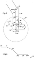
- the display screen 8 can also display a vertical representation of the type of the figure 6 .
- the cartographic calculator may additionally require the display of an approach corridor 50 of a given width 51.
- the hallway approach 50 is centered on the approach path 25 to follow.
- This approach corridor may correspond to the corridor defined by certification regulations
- the approach corridor may possibly have dimensions greater than the dimensions required by the regulations at least locally for safety.
- the approach runway may comprise a straight segment 50 'of the final approach point FAF at the OIP offset point, then an inclined segment 50' from this OIP offset point, however, the straight segment 50 ' can also be extended beyond the OIP offset point.
- the cartographic calculator 4 cooperates with the automatic identification system 5 to list the objects 30 provided with an automatic identification system AIS, TCAS and present in a predetermined OCZ monitoring zone.
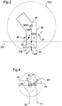
- the OCZ surveillance zone shown on the figure 2 is a circle of radius R1 centered on the platform 20 to reach.
- a danger level of each object is determined with respect to the approach trajectory followed according to rules defined by the manufacturer.
- the horizontal representation of the approach trajectory 25 is displayed as well as for each object: a pad 41 representing the current position of the object, an indication 42 of the direction of movement of the object, and a representation 43 relative to the level of danger of the object.
- the indication 42 may be an arrow directed according to the speed vector of the object and having a length depending on the speed of advance of the object. This length can also take into consideration a given time, the arrow can thus indicate the predictive position of the object at the end of this given time.
- the level of danger can be established by the cartographic calculator which communicates to the display device 7 the data to display and their symbology with possible generation of an audio alert according to the dangerousness.
- the manufacturer can establish three levels of dangerousness displayed through a coloration of the studs 41.
- a first level of danger can induce a first type of coloration represented for example by a white color on the stud 31 of the figure 2 .
- a second level of danger can induce a second type of coloration represented by one of the hatching on the pad 32 of the figure 2 .
- a third level of danger can induce a third type of coloration represented by a black color on the stud 33 of the figure 2 .
- the second type of coloration may be an amber color
- the third type of coloration may be a red color.
- the TFAF time is determined at which the aircraft will reach the final FAF approach point. This step can be undertaken by the cartographic calculator for example.
- the map calculator may be connected to devices for determining the ground speed of the aircraft.
- the cartographic calculator determines the predictive position of each object studied at the end of this time TFAF.
- the aircraft determines where the objects will be when this aircraft reaches the final approach point based on the information transmitted by their automatic identification system.
- the level of danger of each object is established according to its predictive position and its current position with respect to the approach corridor.
- the cartographic calculator can thus give an object the first level of danger when the current position of this object is not located in the approach corridor 50 and when its predictive position will not be located in the approach corridor 50 at the TFAF time.
- the object marked by the stud 31 thus has this first level of danger.
- the second level of danger corresponds to an object having a current position outside the approach corridor 50, but which has a predictive position located in this approach corridor 50.
- the object marked by the stud 32 thus presents this second level dangerousness.
- the third level of danger is associated with an object when its current position and its predictive position are located in the approach corridor 50.
- the stud 33 corresponds to the current position of such an object.
- the system focuses on objects potentially located in front of the aircraft when the FAF final approach point is reached or exceeded, namely the objects located between the line 200 and the top of the sheet on which the figure 3 .
- the current position as well as the direction of movement and the speed of movement of the objects referred to as "intruders" for convenience located either in front of the aircraft 1 or in a circle C1 centered on the aircraft 1 are determined over time.
- the circle diameter is small and smaller than the width of an approach corridor.
- the intruder For each intruder and over time, it is determined according to a processing frequency if the intruder is at a current time located in an approach corridor 50 and if this intruder is located in front of the aircraft 1. If the intruder is not present in approach lane 50 and if the said intruder is in front of aircraft 1, it is determined whether the intruder will enter the approach lane 50 in the future, and if so, when this intruder will enter the approach lane 50.
- an intruder is given the first level of danger represented by a first representation 31 'on the display screen 8 when the intruder is behind the aircraft 1 at a current time, or when the intruder will be behind the aircraft. 'aircraft when entering the approach lane 50, or when the intruder will never enter the approach lane.
- the intruder is associated with the second level of danger represented by a second representation 32 'on the display screen 8 when the intruder is in front of the aircraft 1 when he enters the approach corridor 50.
- the intruder is associated with a third level of danger represented by a third representation 33 'on the display screen 8 when the intruder is in front of the aircraft 1 in the approach corridor 50 at the current time.
- a moving box 55 can be displayed on request and on the display screen.
- This movable box corresponds to the horizontal representation to a quadrilateral of a predetermined fixed width 56 and of a length 57 equal to the product of a constant of the time CTE and ground speed GS of the aircraft 1.
- the time constant may for example be chosen from a list predetermined by the manufacturer.
- the mobile box 55 is centered transversely on the speed vector of the aircraft and extends longitudinally along this speed vector from a representation of the aircraft 1. The moving box thus moves together with the representation of the aircraft. aircraft on the display screen.
- some objects are associated with additional symbology. More particularly, the current position as well as the direction of movement, the speed of movement and the predictive location at the end of said time constant of the objects called "close element" equipped with an automatic system are determined over time. which are present in a predetermined scanning zone Z1 centered on the aircraft,
- the arrow 37 'associated with the stud 37 may flash according to the second symbology.
- the pad 35 may flash according to the third symbology, the arrow 36 'and the pin 36 flashing both according to the fourth symbology.
- the frame of the mobile box may also have a particularity when the stud having the current position of an object is present in this mobile box. For example, the frame can become red.
Landscapes
- Engineering & Computer Science (AREA)
- Radar, Positioning & Navigation (AREA)
- Remote Sensing (AREA)
- Physics & Mathematics (AREA)
- General Physics & Mathematics (AREA)
- Aviation & Aerospace Engineering (AREA)
- Automation & Control Theory (AREA)
- Electromagnetism (AREA)
- Computer Networks & Wireless Communication (AREA)
- Traffic Control Systems (AREA)
- Radar Systems Or Details Thereof (AREA)
Claims (11)
- Verfahren zur Erleichterung der Annäherung an eine Plattform (20) auf einer Flüssigkeitsoberfläche mit einem Luftfahrzeug (1), wobei das Verfahren eine Erstellungsphase aufweist zum Erstellen einer Flugbahn (25) zur Annäherung an eine Plattform, wobei das Verfahren aufweist:- während der Erstellungsphase wird die Annäherungsflugbahn (25) erstellt, um sich einer theoretischen Lage (20') der Plattform (20) zu nähern, wobei die theoretische Lage durch eine Bedienungsperson erfasst wird oder aus einer Datenbank für Plattformen stammt,- während einer Konsolidierungsphase der Annäherungsflugbahn (25):dadurch gekennzeichnet, dass während der Konsolidierungsphase der Annäherungsflugbahn (25) automatisch ein Vektor (45) bestimmt wird, der die theoretische Lage (20') der Plattform mit einer neuen anvisierten Lage (20") verbindet, und die Annäherungsflugbahn (25) automatisch verschoben wird durch Anwendung des Vektors (45), um die neue Lage (20") zu erlangen.∘ die aktuelle Lage (20") der Plattform (20) bestimmt wird,∘ ein Abstand (D1), der die theoretische Lage (20') von der aktuellen Lage (20") trennt, bestimmt wird,∘ ein Alarm ausgelöst wird, wenn der Abstand (D1) größer als ein erster Schwellenwert (S1) ist,
- Verfahren nach Anspruch 1,
dadurch gekennzeichnet, dass die Konsolidierungsphase begonnen wird, sobald eine Information empfangen wird, die die aktuelle Lage der Plattform liefert. - Verfahren nach einem der Ansprüche 1 bis 3,
dadurch gekennzeichnet, dass auf dem Anzeigebildschirm (8) ein Annäherungskorridor (50) mit einer gegebenen Breite (51), der auf der Annäherungsflugbahn (25) zentriert ist, angezeigt wird. - Verfahren nach einem der Ansprüche 1 bis 3,
dadurch gekennzeichnet, dass, während einer Sicherungsphase der Annäherungsflugbahn (25):∘ im Laufe der Zeit die aktuelle Lage sowie die Bewegungsrichtung und die Bewegungsgeschwindigkeit von Objekten (30) bestimmt werden, die mit einem automatischen Identifizierungssystem versehen sind, die in einem vorbestimmten Überwachungsbereich (OCZ) vorhanden sind,∘ ein Gefährlichkeitsgrad eines jeden Objektes bezüglich der gefolgten Annäherungflugbahn, die von dem Luftfahrzeug verfolgt wird, bestimmt wird,∘ auf einem Anzeigebildschirm (8) eine horizontale Darstellung der Annäherungsflugbahn (25) sowie für jedes Objekt eine graphische Darstellung (41), die die aktuelle Lage des Objektes darstellt, eine Anzeige (42) der Bewegungsrichtung des Objekts und eine Darstellung (43) bezüglich des Gefährlichkeitsgrads des Objekts angezeigt werden. - Verfahren nach Anspruch 4,
dadurch gekennzeichnet, dass der vorbestimmte Überwachungsbereich (OCZ) ein Kreis mit einem Radius (R1) ist, der von dem Hersteller definiert wird und auf der zu erreichenden Plattform zentriert ist. - Verfahren nach Anspruch 4,
dadurch gekennzeichnet, dass während der Sicherungsphase, wobei die Annäherungsflugbahn (25) durch einen finalen Annäherungspunkt (FAF) verläuft, bevor dieser finale Annäherungspunkt (FAF) von dem Luftfahrzeug erreicht wird:- die Zeitdauer (TFAF) bestimmt wird, die für das Luftfahrzeug notwendig ist, um den finalen Annäherungspunkt (FAF) zu erreichen,- die prognostizierte Lage, die jedes der Objekte einnehmen wird, wenn das Luftfahrzeug den finalen Annäherungspunkt erreicht hat, bestimmt wird,- der Gefährlichkeitsgrad eines jeden Objektes in Abhängigkeit von seiner prognostizierten Lage und von seiner aktuellen Lage relativ zu einem Annäherungskorridor (50) einer gegebenen Breite (51), der auf der Annäherungsflugbahn (25) zentriert ist, bestimmt wird. - Verfahren nach Anspruch 6,
dadurch gekennzeichnet, dass ein erster, ein zweiter und ein dritter Gefährlichkeitsgrad eingesetzt werden, wobei ein Objekt verbunden wird mit:- dem ersten Gefährlichkeitsgrad, wenn die aktuelle Lage dieses Objektes nicht in dem Annäherungskorridor (50) liegt und wenn seine prognostizierte Lage nicht in dem Annäherungskorridor (50) liegen wird, wenn das Luftfahrzeug (1) seinen finalen Annäherungspunkt (FAF) erreicht hat,- dem zweiten Gefährlichkeitsgrad, wenn die aktuelle Lage dieses Objekts nicht in dem Annäherungskorridor (50) liegt und wenn seine prognostizierte Lage in dem Annäherungskorridor (50) liegen wird, wenn das Luftfahrzeug (1) seinen finalen Annäherungspunkt (FAF) erreicht hat,- dem dritten Gefährlichkeitsgrad, wenn die aktuelle Lage dieses Objekts in dem Annäherungskorridor (50) liegt und wenn seine prognostizierte Lage in dem Annäherungskorridor (50) liegen wird, wenn das Luftfahrzeug (1) den finalen Annäherungspunkt (FAF) erreicht hat. - Verfahren nach einem der Ansprüche 4 bis 7,
dadurch gekennzeichnet, dass eine Änderung des Kurses (CRS1, CRS2) der Annäherungsflugbahn (25) während einer Phase der Erstellung einer alternativen Annäherungsflugbahn (25') erlaubt wird. - Verfahren nach Anspruch 8,
dadurch gekennzeichnet, dass in erster Linie die erstellte Annäherungsflugbahn (25) und die alternative Annäherungsflugbahn (25') auf dem Anzeigebildschirm (8) mit verschiedenen Darstellungen angezeigt werden. - Verfahren nach einem der Ansprüche 4 bis 9,
dadurch gekennzeichnet, dass, während der Sicherungsphase, wobei die Annäherungsflugbahn durch einen finalen Annäherungspunkt (FAF) verläuft, nachdem dieser finale Annäherungspunkt (FAF) erreicht ist:- im Laufe der Zeit die aktuelle Lage sowie die Bewegungsrichtung und die Bewegungsgeschwindigkeit von "Eindringling" genannten Objekten bestimmt werden, die sich vor dem Luftfahrzeug (1) oder in einem Kreis (C1), der auf dem Luftfahrzeug (1) zentriert ist und einen vorbestimmten Durchmesser aufweist, befinden,- für jeden Eindringling und im Laufe der Zeit:∘ bestimmt wird, ob der Eindringling zu einem aktuellen Zeitpunkt in dem Annäherungskorridor (50), der die Annäherungsflugbahn umgibt, gelegen ist, und ob sich der Eindringling vor dem Luftfahrzeug (1) befindet,∘ wenn der Eindringling sich nicht in dem Annäherungskorridor (50) befindet und wenn der Eindringling vor dem Luftfahrzeug (1) gelegen ist, bestimmt wird, ob der Eindringling in Zukunft in den Annäherungskorridor (50) eintreten wird, und falls dies zutrifft, wann der Eindringling in den Annäherungskorridor (50) eintreten wird,∘ der Eindringling mit einem ersten Gefährlichkeitsgrad verbunden wird, der durch eine erste Darstellung auf dem Anzeigebildschirm (8) dargestellt wird, wenn sich der Eindringling zu einem aktuellen Zeitpunkt hinter dem Luftfahrzeug (1) befindet oder wenn der Eindringling hinter dem Luftfahrzeug sein wird, wenn er in den Annäherungskorridor (50) eintreten wird,∘ der Eindringling mit einem zweiten Gefährlichkeitsgrad verbunden wird, der durch eine zweite Darstellung auf dem Anzeigebildschirm (8) dargestellt wird, wenn sich der Eindringling vor dem Luftfahrzeug (1) befinden wird, wenn dieser in den Annäherungskorridor (50) eintreten wird,∘ der Eindringling mit einem dritten Gefährlichkeitsgrad verbunden wird, der durch eine dritte Darstellung auf dem Anzeigebildschirm (8) dargestellt wird, wenn sich der Eindringling zum aktuellen Zeitpunkt vor dem Luftfahrzeug (1) in dem Annäherungskorridor befindet. - Verfahren nach einem der Ansprüche 4 bis 10,
dadurch gekennzeichnet, dass:- auf dem Anzeigebildschirm (8) eine bewegliche Box (55) angezeigt wird, die ein Viereck mit einer vorbestimmten festen Breite (56) und einer Länge (57) darstellt, die gleich dem Produkt aus einer Zeitkonstante (CTE) und der Geschwindigkeit über Grund (GS) des Luftfahrzeugs (1) ist, wobei die bewegliche Box (55) in Querrichtung auf dem Geschwindigkeitsvektor des Luftfahrzeugs zentriert ist und sich in Längsrichtung ausgehend von einer Darstellung des Luftfahrzeugs (1) erstreckt,- im Laufe der Zeit die aktuelle Lage sowie die Bewegungsrichtung, die Bewegungsgeschwindigkeit und die prognostizierte Lage bei der Zeitkonstanten von Objekten, die "näher gekommene Elemente" genannt werden, die auf der Flüssigkeitsoberfläche liegen, und mit einem automatischen Identifizierungssystem versehen sind, und die in einem auf dem Luftfahrzeug zentrierten vorbestimmten Abtastbereich gelegen sind, bestimmt werden,- auf dem Anzeigebildschirm (8) für jedes näher gekommene Element angezeigt wird:∘ eine erste Symbologie, wenn die aktuelle Lage und die prognostizierte Lage nicht in der beweglichen Box (55) liegen,∘ eine zweite Symbologie, wenn die aktuelle Lage nicht in der beweglichen Box (55) liegt und wenn die prognostizierte Lage in der beweglichen Box (55) liegt,∘ eine dritte Symbologie, wenn die aktuelle Lage in der beweglichen Box (55) liegt und wenn die prognostizierte Lage nicht in der beweglichen Box (55) liegt,∘ eine vierte Symbologie, wenn die aktuelle Lage und die prognostizierte Lage in der beweglichen Box (55) liegen.
Applications Claiming Priority (1)
| Application Number | Priority Date | Filing Date | Title |
|---|---|---|---|
| FR1301272A FR3006800B1 (fr) | 2013-06-05 | 2013-06-05 | Procede d'approche d'une plateforme |
Publications (2)
| Publication Number | Publication Date |
|---|---|
| EP2811358A1 EP2811358A1 (de) | 2014-12-10 |
| EP2811358B1 true EP2811358B1 (de) | 2017-11-22 |
Family
ID=49274692
Family Applications (2)
| Application Number | Title | Priority Date | Filing Date |
|---|---|---|---|
| EP14001499.4A Active EP2811358B1 (de) | 2013-06-05 | 2014-04-28 | Annäherungsverfahren einer Plattform |
| EP14001498.6A Active EP2811357B1 (de) | 2013-06-05 | 2014-04-28 | Annäherungsverfahren einer Plattform |
Family Applications After (1)
| Application Number | Title | Priority Date | Filing Date |
|---|---|---|---|
| EP14001498.6A Active EP2811357B1 (de) | 2013-06-05 | 2014-04-28 | Annäherungsverfahren einer Plattform |
Country Status (3)
| Country | Link |
|---|---|
| US (2) | US10024686B2 (de) |
| EP (2) | EP2811358B1 (de) |
| FR (1) | FR3006800B1 (de) |
Families Citing this family (14)
| Publication number | Priority date | Publication date | Assignee | Title |
|---|---|---|---|---|
| FR3010541B1 (fr) * | 2013-09-10 | 2015-10-02 | Airbus Operations Sas | Procede et dispositif de gestion automatique d'un changement de trajectoire de vol sur un aeronef, en particulier pour un vol a basse altitude. |
| US9584191B2 (en) | 2013-12-20 | 2017-02-28 | Southern Avionics Co. | Antenna tuning unit |
| US10431099B2 (en) * | 2014-02-21 | 2019-10-01 | FLIR Belgium BVBA | Collision avoidance systems and methods |
| US9830828B2 (en) * | 2015-03-24 | 2017-11-28 | Honeywell International Inc. | Systems and method for AIS transponder integration with ILS/VOR receivers |
| FR3058555B1 (fr) * | 2016-11-10 | 2021-02-12 | Thales Sa | Uniformisation des approches plateforme pour aeronef |
| FR3061343B1 (fr) * | 2016-12-22 | 2020-06-19 | Thales | Systeme d'aide a l'atterrissage d'un aeronef a voilure tournante sur une plateforme offshore |
| FR3063142B1 (fr) * | 2017-02-22 | 2021-06-18 | Airbus Safran Launchers Sas | Procede et disposition de surveillance de l'integrite d'une trajectoire d'un engin volant, spatial ou aerien |
| US10890924B2 (en) | 2017-08-17 | 2021-01-12 | Textron Innovations Inc. | System and method for rotorcraft offshore approach |
| US20190236965A1 (en) * | 2018-01-29 | 2019-08-01 | Honeywell International Inc. | System and method for providing prioritized alternate approach procedures |
| FR3102881B1 (fr) * | 2019-10-31 | 2022-09-09 | Allard Jerome | Dispositif et procédé pour faciliter un amerrissage d’urgence. |
| FR3107388B1 (fr) | 2020-02-14 | 2022-03-04 | Airbus Helicopters | Procédé et système d’aide à la navigation pour un aéronef par détection d’objets maritimes en vue d’un vol d’approche, d’une mise en vol stationnaire ou d’un atterrissage |
| US12269610B2 (en) | 2021-11-15 | 2025-04-08 | Honeywell International Inc. | Systems and methods for providing safe landing assistance for an aerial vehicle |
| US12462692B2 (en) * | 2024-01-17 | 2025-11-04 | Honeywell International Inc. | System and method for camera assisted stable approach using sensor fusion |
| CN119495214B (zh) * | 2024-11-26 | 2025-10-17 | 中国电子科技集团公司第十五研究所 | 一种基于航线分解的飞机航线计算方法 |
Family Cites Families (17)
| Publication number | Priority date | Publication date | Assignee | Title |
|---|---|---|---|---|
| US4021010A (en) * | 1975-08-29 | 1977-05-03 | Bliss John H | Method and apparatus to overcome aircraft control problems due to wind shear |
| US4316252A (en) | 1979-08-10 | 1982-02-16 | The Boeing Company | Apparatus for determining the position of an aircraft with respect to the runway |
| US5377937A (en) * | 1991-09-03 | 1995-01-03 | The Boeing Company | Aircraft flare control system utilizing an envelope limiter |
| US5343395A (en) | 1992-08-26 | 1994-08-30 | Watts Alan B | Aircraft landing guidance system and method |
| FR2810146A1 (fr) * | 2000-06-09 | 2001-12-14 | Thomson Csf | Procede d'elaboration d'une trajectoire d'evitement dans le plan horizontal pour aeronef en vue de la resolution d'un conflit de trafic |
| GB2382250B (en) | 2001-08-03 | 2006-01-04 | Furuno Electric Co | Vehicle information display apparatus |
| US6711479B1 (en) | 2001-08-30 | 2004-03-23 | Honeywell International, Inc. | Avionics system for determining terminal flightpath |
| JP3763004B1 (ja) | 2005-08-03 | 2006-04-05 | 国土交通省国土技術政策総合研究所長 | 航空機進出入路付近の船舶監視システム、及び航空機進出入路付近の船舶監視方法 |
| US8949011B2 (en) * | 2005-09-14 | 2015-02-03 | Novatel Inc. | Helicopter ship board landing system |
| US8296001B1 (en) | 2006-11-13 | 2012-10-23 | Garmin Switzerland Gmbh | Marine vessel navigation device, system and method |
| US8442706B2 (en) * | 2008-12-30 | 2013-05-14 | Sikorsky Aircraft Corporation | Module for integrated approach to an offshore facility |
| FR2943778B1 (fr) | 2009-03-27 | 2015-04-10 | Thales Sa | Dispositif interactif de navigation |
| US8362925B2 (en) * | 2009-05-05 | 2013-01-29 | Honeywell International Inc. | Avionics display system and method for generating flight information pertaining to neighboring aircraft |
| DE102009041652B4 (de) | 2009-09-17 | 2017-12-28 | Airbus Defence and Space GmbH | -Verfahren zum automatischen Landen eines Luftfahrzeugs |
| US8830090B2 (en) * | 2011-07-08 | 2014-09-09 | The Boeing Company | Display of current trend and/or future position of vehicular traffic |
| FR3002675B1 (fr) | 2013-02-25 | 2015-04-03 | Eurocopter France | Procede pour faciliter l approche d une plateforme |
| US9580173B1 (en) * | 2014-08-28 | 2017-02-28 | X Development Llc | Translational correction of payload-release device based on tracked position |
-
2013
- 2013-06-05 FR FR1301272A patent/FR3006800B1/fr active Active
-
2014
- 2014-04-28 EP EP14001499.4A patent/EP2811358B1/de active Active
- 2014-04-28 EP EP14001498.6A patent/EP2811357B1/de active Active
- 2014-06-03 US US14/294,397 patent/US10024686B2/en active Active
- 2014-06-03 US US14/294,463 patent/US9151637B2/en active Active
Non-Patent Citations (1)
| Title |
|---|
| None * |
Also Published As
| Publication number | Publication date |
|---|---|
| US20140365044A1 (en) | 2014-12-11 |
| EP2811357A1 (de) | 2014-12-10 |
| US10024686B2 (en) | 2018-07-17 |
| FR3006800B1 (fr) | 2015-06-12 |
| FR3006800A1 (fr) | 2014-12-12 |
| EP2811358A1 (de) | 2014-12-10 |
| EP2811357B1 (de) | 2017-08-16 |
| US9151637B2 (en) | 2015-10-06 |
| US20140365045A1 (en) | 2014-12-11 |
Similar Documents
| Publication | Publication Date | Title |
|---|---|---|
| EP2811358B1 (de) | Annäherungsverfahren einer Plattform | |
| US9310222B1 (en) | Flight assistant with automatic configuration and landing site selection method and apparatus | |
| US7963618B2 (en) | Systems and methods for providing aircraft runway guidance | |
| US9387938B1 (en) | Terrain awareness and warning systems and methods | |
| CA2509942C (fr) | Dispositif d'affichage anticollision terrain embarque | |
| RU2360292C1 (ru) | Способ и устройство для содействия наземной навигации самолета в аэропорту | |
| JP5305681B2 (ja) | 交通手段の交通セーフティを改善するための方法および装置 | |
| EP2309474B1 (de) | Überwachungssystem in der Anflugphase für Luftfahrzeuge | |
| FR2905756A1 (fr) | Procede et dispositif pour aeronef,d'evitement des collisions avec le terrain | |
| FR2917222A1 (fr) | Dispositif et procede de prevention de collision pour un vehicule au sol | |
| EP0928952A1 (de) | Verfahren und Vorrichtung zur Grundkollisionsvermeidung für Flugzeuge | |
| EP2770395B1 (de) | Verfahren zum Erleichtern des Annäherns einer Plattform | |
| FR2810146A1 (fr) | Procede d'elaboration d'une trajectoire d'evitement dans le plan horizontal pour aeronef en vue de la resolution d'un conflit de trafic | |
| FR2932279A1 (fr) | Dispositif et procede de surveillance des obstructions dans l'environnement proche d'un aeronef. | |
| EP3216021B1 (de) | Verfahren und vorrichtung zum lenken eines flugzeugs | |
| JPH1035594A (ja) | 旋回予期を伴う航空機のための地表衝突予防装置 | |
| WO2007054448A1 (fr) | Systeme d'evitement de terrain pour aeronefs de transport | |
| FR3003989A1 (fr) | Procede pour localiser et guider un vehicule par voie optique par rapport a un aeroport | |
| US7855675B2 (en) | Method and device for detecting an environning aircraft | |
| CA2640527A1 (fr) | Procede et dispositif d'ajustement automatique d'une image d'un ecran de navigation d'aeronef | |
| CA2699459A1 (en) | Method of presenting anti-collision information in a head-up display for aircraft | |
| US12260769B1 (en) | System and apparatus for reducing the urgency of a flight condition | |
| EP2320290A1 (de) | Relativgeschwindigkeitsmesseinrichtung zur Steuerung eines unbemannten Flugzeugs | |
| EP2996008B1 (de) | Verfahren zum erleichtern des annäherns an eine plattform | |
| FR2893747A1 (fr) | Systeme, assiste par satellite, d'alerte de collisions et de gestion du trafic de vehicules, tels que des aeronefs |
Legal Events
| Date | Code | Title | Description |
|---|---|---|---|
| PUAI | Public reference made under article 153(3) epc to a published international application that has entered the european phase |
Free format text: ORIGINAL CODE: 0009012 |
|
| 17P | Request for examination filed |
Effective date: 20140428 |
|
| AK | Designated contracting states |
Kind code of ref document: A1 Designated state(s): AL AT BE BG CH CY CZ DE DK EE ES FI FR GB GR HR HU IE IS IT LI LT LU LV MC MK MT NL NO PL PT RO RS SE SI SK SM TR |
|
| AX | Request for extension of the european patent |
Extension state: BA ME |
|
| R17P | Request for examination filed (corrected) |
Effective date: 20150107 |
|
| RBV | Designated contracting states (corrected) |
Designated state(s): AL AT BE BG CH CY CZ DE DK EE ES FI FR GB GR HR HU IE IS IT LI LT LU LV MC MK MT NL NO PL PT RO RS SE SI SK SM TR |
|
| 17Q | First examination report despatched |
Effective date: 20161011 |
|
| GRAP | Despatch of communication of intention to grant a patent |
Free format text: ORIGINAL CODE: EPIDOSNIGR1 |
|
| INTG | Intention to grant announced |
Effective date: 20170907 |
|
| GRAS | Grant fee paid |
Free format text: ORIGINAL CODE: EPIDOSNIGR3 |
|
| GRAA | (expected) grant |
Free format text: ORIGINAL CODE: 0009210 |
|
| AK | Designated contracting states |
Kind code of ref document: B1 Designated state(s): AL AT BE BG CH CY CZ DE DK EE ES FI FR GB GR HR HU IE IS IT LI LT LU LV MC MK MT NL NO PL PT RO RS SE SI SK SM TR |
|
| REG | Reference to a national code |
Ref country code: GB Ref legal event code: FG4D Free format text: NOT ENGLISH |
|
| REG | Reference to a national code |
Ref country code: CH Ref legal event code: EP |
|
| REG | Reference to a national code |
Ref country code: IE Ref legal event code: FG4D Free format text: LANGUAGE OF EP DOCUMENT: FRENCH |
|
| REG | Reference to a national code |
Ref country code: AT Ref legal event code: REF Ref document number: 948955 Country of ref document: AT Kind code of ref document: T Effective date: 20171215 |
|
| REG | Reference to a national code |
Ref country code: DE Ref legal event code: R096 Ref document number: 602014017435 Country of ref document: DE |
|
| REG | Reference to a national code |
Ref country code: NL Ref legal event code: MP Effective date: 20171122 |
|
| REG | Reference to a national code |
Ref country code: LT Ref legal event code: MG4D |
|
| REG | Reference to a national code |
Ref country code: AT Ref legal event code: MK05 Ref document number: 948955 Country of ref document: AT Kind code of ref document: T Effective date: 20171122 |
|
| REG | Reference to a national code |
Ref country code: FR Ref legal event code: PLFP Year of fee payment: 5 |
|
| PG25 | Lapsed in a contracting state [announced via postgrant information from national office to epo] |
Ref country code: ES Free format text: LAPSE BECAUSE OF FAILURE TO SUBMIT A TRANSLATION OF THE DESCRIPTION OR TO PAY THE FEE WITHIN THE PRESCRIBED TIME-LIMIT Effective date: 20171122 Ref country code: NO Free format text: LAPSE BECAUSE OF FAILURE TO SUBMIT A TRANSLATION OF THE DESCRIPTION OR TO PAY THE FEE WITHIN THE PRESCRIBED TIME-LIMIT Effective date: 20180222 Ref country code: LT Free format text: LAPSE BECAUSE OF FAILURE TO SUBMIT A TRANSLATION OF THE DESCRIPTION OR TO PAY THE FEE WITHIN THE PRESCRIBED TIME-LIMIT Effective date: 20171122 Ref country code: SE Free format text: LAPSE BECAUSE OF FAILURE TO SUBMIT A TRANSLATION OF THE DESCRIPTION OR TO PAY THE FEE WITHIN THE PRESCRIBED TIME-LIMIT Effective date: 20171122 Ref country code: NL Free format text: LAPSE BECAUSE OF FAILURE TO SUBMIT A TRANSLATION OF THE DESCRIPTION OR TO PAY THE FEE WITHIN THE PRESCRIBED TIME-LIMIT Effective date: 20171122 Ref country code: FI Free format text: LAPSE BECAUSE OF FAILURE TO SUBMIT A TRANSLATION OF THE DESCRIPTION OR TO PAY THE FEE WITHIN THE PRESCRIBED TIME-LIMIT Effective date: 20171122 |
|
| PG25 | Lapsed in a contracting state [announced via postgrant information from national office to epo] |
Ref country code: LV Free format text: LAPSE BECAUSE OF FAILURE TO SUBMIT A TRANSLATION OF THE DESCRIPTION OR TO PAY THE FEE WITHIN THE PRESCRIBED TIME-LIMIT Effective date: 20171122 Ref country code: BG Free format text: LAPSE BECAUSE OF FAILURE TO SUBMIT A TRANSLATION OF THE DESCRIPTION OR TO PAY THE FEE WITHIN THE PRESCRIBED TIME-LIMIT Effective date: 20180222 Ref country code: GR Free format text: LAPSE BECAUSE OF FAILURE TO SUBMIT A TRANSLATION OF THE DESCRIPTION OR TO PAY THE FEE WITHIN THE PRESCRIBED TIME-LIMIT Effective date: 20180223 Ref country code: HR Free format text: LAPSE BECAUSE OF FAILURE TO SUBMIT A TRANSLATION OF THE DESCRIPTION OR TO PAY THE FEE WITHIN THE PRESCRIBED TIME-LIMIT Effective date: 20171122 Ref country code: RS Free format text: LAPSE BECAUSE OF FAILURE TO SUBMIT A TRANSLATION OF THE DESCRIPTION OR TO PAY THE FEE WITHIN THE PRESCRIBED TIME-LIMIT Effective date: 20171122 Ref country code: AT Free format text: LAPSE BECAUSE OF FAILURE TO SUBMIT A TRANSLATION OF THE DESCRIPTION OR TO PAY THE FEE WITHIN THE PRESCRIBED TIME-LIMIT Effective date: 20171122 |
|
| PG25 | Lapsed in a contracting state [announced via postgrant information from national office to epo] |
Ref country code: SK Free format text: LAPSE BECAUSE OF FAILURE TO SUBMIT A TRANSLATION OF THE DESCRIPTION OR TO PAY THE FEE WITHIN THE PRESCRIBED TIME-LIMIT Effective date: 20171122 Ref country code: CZ Free format text: LAPSE BECAUSE OF FAILURE TO SUBMIT A TRANSLATION OF THE DESCRIPTION OR TO PAY THE FEE WITHIN THE PRESCRIBED TIME-LIMIT Effective date: 20171122 Ref country code: CY Free format text: LAPSE BECAUSE OF FAILURE TO SUBMIT A TRANSLATION OF THE DESCRIPTION OR TO PAY THE FEE WITHIN THE PRESCRIBED TIME-LIMIT Effective date: 20171122 Ref country code: DK Free format text: LAPSE BECAUSE OF FAILURE TO SUBMIT A TRANSLATION OF THE DESCRIPTION OR TO PAY THE FEE WITHIN THE PRESCRIBED TIME-LIMIT Effective date: 20171122 Ref country code: EE Free format text: LAPSE BECAUSE OF FAILURE TO SUBMIT A TRANSLATION OF THE DESCRIPTION OR TO PAY THE FEE WITHIN THE PRESCRIBED TIME-LIMIT Effective date: 20171122 |
|
| REG | Reference to a national code |
Ref country code: DE Ref legal event code: R097 Ref document number: 602014017435 Country of ref document: DE |
|
| PG25 | Lapsed in a contracting state [announced via postgrant information from national office to epo] |
Ref country code: SM Free format text: LAPSE BECAUSE OF FAILURE TO SUBMIT A TRANSLATION OF THE DESCRIPTION OR TO PAY THE FEE WITHIN THE PRESCRIBED TIME-LIMIT Effective date: 20171122 Ref country code: RO Free format text: LAPSE BECAUSE OF FAILURE TO SUBMIT A TRANSLATION OF THE DESCRIPTION OR TO PAY THE FEE WITHIN THE PRESCRIBED TIME-LIMIT Effective date: 20171122 Ref country code: PL Free format text: LAPSE BECAUSE OF FAILURE TO SUBMIT A TRANSLATION OF THE DESCRIPTION OR TO PAY THE FEE WITHIN THE PRESCRIBED TIME-LIMIT Effective date: 20171122 |
|
| PG25 | Lapsed in a contracting state [announced via postgrant information from national office to epo] |
Ref country code: MT Free format text: LAPSE BECAUSE OF FAILURE TO SUBMIT A TRANSLATION OF THE DESCRIPTION OR TO PAY THE FEE WITHIN THE PRESCRIBED TIME-LIMIT Effective date: 20171122 |
|
| PLBE | No opposition filed within time limit |
Free format text: ORIGINAL CODE: 0009261 |
|
| STAA | Information on the status of an ep patent application or granted ep patent |
Free format text: STATUS: NO OPPOSITION FILED WITHIN TIME LIMIT |
|
| 26N | No opposition filed |
Effective date: 20180823 |
|
| REG | Reference to a national code |
Ref country code: DE Ref legal event code: R119 Ref document number: 602014017435 Country of ref document: DE |
|
| PG25 | Lapsed in a contracting state [announced via postgrant information from national office to epo] |
Ref country code: SI Free format text: LAPSE BECAUSE OF FAILURE TO SUBMIT A TRANSLATION OF THE DESCRIPTION OR TO PAY THE FEE WITHIN THE PRESCRIBED TIME-LIMIT Effective date: 20171122 Ref country code: MC Free format text: LAPSE BECAUSE OF FAILURE TO SUBMIT A TRANSLATION OF THE DESCRIPTION OR TO PAY THE FEE WITHIN THE PRESCRIBED TIME-LIMIT Effective date: 20171122 |
|
| REG | Reference to a national code |
Ref country code: CH Ref legal event code: PL |
|
| REG | Reference to a national code |
Ref country code: BE Ref legal event code: MM Effective date: 20180430 |
|
| REG | Reference to a national code |
Ref country code: IE Ref legal event code: MM4A |
|
| PG25 | Lapsed in a contracting state [announced via postgrant information from national office to epo] |
Ref country code: DE Free format text: LAPSE BECAUSE OF NON-PAYMENT OF DUE FEES Effective date: 20181101 Ref country code: LU Free format text: LAPSE BECAUSE OF NON-PAYMENT OF DUE FEES Effective date: 20180428 |
|
| PG25 | Lapsed in a contracting state [announced via postgrant information from national office to epo] |
Ref country code: LI Free format text: LAPSE BECAUSE OF NON-PAYMENT OF DUE FEES Effective date: 20180430 Ref country code: BE Free format text: LAPSE BECAUSE OF NON-PAYMENT OF DUE FEES Effective date: 20180430 Ref country code: CH Free format text: LAPSE BECAUSE OF NON-PAYMENT OF DUE FEES Effective date: 20180430 |
|
| PG25 | Lapsed in a contracting state [announced via postgrant information from national office to epo] |
Ref country code: IE Free format text: LAPSE BECAUSE OF NON-PAYMENT OF DUE FEES Effective date: 20180428 |
|
| PG25 | Lapsed in a contracting state [announced via postgrant information from national office to epo] |
Ref country code: TR Free format text: LAPSE BECAUSE OF FAILURE TO SUBMIT A TRANSLATION OF THE DESCRIPTION OR TO PAY THE FEE WITHIN THE PRESCRIBED TIME-LIMIT Effective date: 20171122 |
|
| PG25 | Lapsed in a contracting state [announced via postgrant information from national office to epo] |
Ref country code: HU Free format text: LAPSE BECAUSE OF FAILURE TO SUBMIT A TRANSLATION OF THE DESCRIPTION OR TO PAY THE FEE WITHIN THE PRESCRIBED TIME-LIMIT; INVALID AB INITIO Effective date: 20140428 Ref country code: PT Free format text: LAPSE BECAUSE OF FAILURE TO SUBMIT A TRANSLATION OF THE DESCRIPTION OR TO PAY THE FEE WITHIN THE PRESCRIBED TIME-LIMIT Effective date: 20171122 |
|
| PG25 | Lapsed in a contracting state [announced via postgrant information from national office to epo] |
Ref country code: MK Free format text: LAPSE BECAUSE OF NON-PAYMENT OF DUE FEES Effective date: 20171122 |
|
| PG25 | Lapsed in a contracting state [announced via postgrant information from national office to epo] |
Ref country code: AL Free format text: LAPSE BECAUSE OF FAILURE TO SUBMIT A TRANSLATION OF THE DESCRIPTION OR TO PAY THE FEE WITHIN THE PRESCRIBED TIME-LIMIT Effective date: 20171122 Ref country code: IS Free format text: LAPSE BECAUSE OF FAILURE TO SUBMIT A TRANSLATION OF THE DESCRIPTION OR TO PAY THE FEE WITHIN THE PRESCRIBED TIME-LIMIT Effective date: 20180322 |
|
| P01 | Opt-out of the competence of the unified patent court (upc) registered |
Effective date: 20230530 |
|
| PGFP | Annual fee paid to national office [announced via postgrant information from national office to epo] |
Ref country code: GB Payment date: 20250423 Year of fee payment: 12 |
|
| PGFP | Annual fee paid to national office [announced via postgrant information from national office to epo] |
Ref country code: IT Payment date: 20250424 Year of fee payment: 12 |
|
| PGFP | Annual fee paid to national office [announced via postgrant information from national office to epo] |
Ref country code: FR Payment date: 20250425 Year of fee payment: 12 |