EP2811496A2 - Electromagnetic connectors - Google Patents
Electromagnetic connectors Download PDFInfo
- Publication number
- EP2811496A2 EP2811496A2 EP14166908.5A EP14166908A EP2811496A2 EP 2811496 A2 EP2811496 A2 EP 2811496A2 EP 14166908 A EP14166908 A EP 14166908A EP 2811496 A2 EP2811496 A2 EP 2811496A2
- Authority
- EP
- European Patent Office
- Prior art keywords
- magnetic
- core
- module
- backplane
- cores
- Prior art date
- Legal status (The legal status is an assumption and is not a legal conclusion. Google has not performed a legal analysis and makes no representation as to the accuracy of the status listed.)
- Granted
Links
Images


Classifications
-
- H—ELECTRICITY
- H01—ELECTRIC ELEMENTS
- H01F—MAGNETS; INDUCTANCES; TRANSFORMERS; SELECTION OF MATERIALS FOR THEIR MAGNETIC PROPERTIES
- H01F38/00—Adaptations of transformers or inductances for specific applications or functions
- H01F38/14—Inductive couplings
-
- H—ELECTRICITY
- H01—ELECTRIC ELEMENTS
- H01F—MAGNETS; INDUCTANCES; TRANSFORMERS; SELECTION OF MATERIALS FOR THEIR MAGNETIC PROPERTIES
- H01F41/00—Apparatus or processes specially adapted for manufacturing or assembling magnets, inductances or transformers; Apparatus or processes specially adapted for manufacturing materials characterised by their magnetic properties
- H01F41/02—Apparatus or processes specially adapted for manufacturing or assembling magnets, inductances or transformers; Apparatus or processes specially adapted for manufacturing materials characterised by their magnetic properties for manufacturing cores, coils, or magnets
-
- Y—GENERAL TAGGING OF NEW TECHNOLOGICAL DEVELOPMENTS; GENERAL TAGGING OF CROSS-SECTIONAL TECHNOLOGIES SPANNING OVER SEVERAL SECTIONS OF THE IPC; TECHNICAL SUBJECTS COVERED BY FORMER USPC CROSS-REFERENCE ART COLLECTIONS [XRACs] AND DIGESTS
- Y10—TECHNICAL SUBJECTS COVERED BY FORMER USPC
- Y10T—TECHNICAL SUBJECTS COVERED BY FORMER US CLASSIFICATION
- Y10T29/00—Metal working
- Y10T29/49—Method of mechanical manufacture
- Y10T29/49002—Electrical device making
- Y10T29/4902—Electromagnet, transformer or inductor
- Y10T29/49071—Electromagnet, transformer or inductor by winding or coiling
Definitions
- the present invention relates to the field of electrical connectors.
- the preferred embodiments of the present invention are used as connectors between backplanes and modules mounted on the backplanes, and accordingly the prior art relating to such connectors will be discussed. However it is to be understood that use of the present invention is not so limited, and the invention may be adapted for as wide range of use.
- the connector housings are round and include an alignment feature plus a rotary collar on one connector member that screws onto the other connector member to maintain positive engagement of the connector members, with an 0-ring providing the ultimate seal of the pins and sockets in the connector.
- a backplane is a printed circuit board into which boards or modules are "plugged”, which backplane printed circuit board provides power to and/or communication with the module or printed circuit mounted on the backplane printed circuit board, or the entire assembly that includes such a backplane printed circuit board.
- a simple edge connector is adequate for applications wherein one can be assured that the environment will not be hostile.
- circuit failure detection techniques and/or error detection and correction techniques are commonly used, as is redundancy in circuitry to provide high reliability in circuit operation over long periods of time.
- corrosion is a persistent problem and may render an initially good contact nonfunctional, as such assemblies may sit almost indefinitely without attention until a failure does occur. Therefore conventional connectors remain a weak link in the overall system.
- references are made to primary windings and secondary windings.
- a primary winding refers to a winding on the backplane
- a secondary winding is a winding in the module.
- this convention is traditional.
- signal transfer this convention may or may not be traditional, depending on the direction of the signaling, and in the case of bidirectional signaling, is arbitrary.
- the word module as used herein is used in a most general sense.
- a section of a backplane circuit board 26 in accordance with one embodiment of the present invention may be seen.
- a typical backplane circuit board 26 in accordance with this embodiment will have a plurality of openings or holes 20 there through, each for the receipt of an I-core during assembly of the backplane, together with one or more groups of openings 22 and 24, each for receipt of an E-core.
- An I-core of the type preferably used will be in the form of a round cylindrical slug of magnetic material, in a preferred embodiment a ferrite suitable for use at high frequencies.
- the E-cores of a typical embodiment will be conventional E-cores, in the embodiment being described, also ferrite E-cores which may be the same grade of ferrite or a different grade of ferrite than the I-cores.
- the E-core devices are used for the transfer of power to a module "plugged" into the backplane using a connector in accordance with an embodiment of the present invention, whereas the I-core devices are used for communication purposes.
- the E-core ferrite (or other material) will be selected for its relatively high saturation density for best power transfer, whereas the I-core ferrite (or other material) will be selected for its high frequency capabilities to assure maximum signal communication bandwidth. Consequently, one aspect of this invention is the separation of the power and signal transfer rather than trying to transfer power and signals in a single magnetic device, and also the optional use of different magnetic materials, preferably the use of different grades of ferrite, for the power and signal transfer devices to allow maximizing the performance of each.
- the backplane circuit board 26 of Fig. 1 will typically be a multilayer board with planar (printed) windings 25 and 27 on each of the multiple layers connected in series with the same winding sense to achieve multiple turn windings, each associated with an I-core opening 20 or the center opening 22 of an E-core opening group 22, 24.
- planar windings are well known and may be formed, by way of example, by forming printed helical or modified helical conductive traces 25 of opposite winding sense on alternate layers of the multilayered printed circuit board 26 and then by connecting the inner ends of the conductive traces of the first and second layers, the outer ends of the conductive traces on the second and third layers, etc.
- Such interconnection may be by way of example by the use of plated through holes at different locations (angles) around the inner and outer peripheries of the windings.
- the interconnector may be made as between alternate board layers as the multilayer circuit board is fabricated. By using such a winding, the total number of turns that may be achieved, while less than a typical wire wound coil, can still be substantial.
- the planar windings could be around either or both regions 24, or around both regions 24 and 22 as long as they were properly interconnected to achieve the required complementary winding sense.
- a section of the circuit board 26 with E-cores 28 and I-cores 30 placed therein a label 32 with an adhesive on the top surface thereof is placed under the circuit board 26 and the E-cores 28 and I-cores 30 are placed in position in the board 32 by a typical pick-and-place machine, with the E-cores and I-cores strongly adhering to the adhesive side of the label 32.
- the openings in the printed circuit board 26 are slightly larger than the E-cores 28 and I-cores 30 so as to leave some gap around the cores for subsequent filling by an appropriate potting compound.
- the potting compound may be a hard potting compound such as an epoxy or alternatively may be a flexible potting compound such as a silicon rubber.
- a silicon rubber will provide some flexibility between the E-cores 28 and I-cores 30 and the backplane printed circuit board 26, if needed. However such flexibility may not be needed in that the combination of the printed circuit board and a rigid potting material makes the printed circuit board very rigid to avoid backplane flexing. Also the backplane printed circuit board will not be subject to the relatively high forces of prior art backplane printed circuit boards because of the absence of any high forces thereon required for full prior art connector engagement, though vibration may be encountered in some applications. In the claims to follow, materials such a epoxy and silicon rubber are considered positive mounts for the respective cores because they hold the cores in place, as opposed to being spring mounted to accommodate meaningful deflection under force.
- the assembled backplane printed circuit board 26 will in turn become part of a larger assembly forming some part of a support chassis which may vary considerably, depending on the application.
- the E-cores 28 on the backplane printed circuit board 26 meet with a respective E-core in a module to be connected to the backplane. Since in preferred embodiments such E-cores are used for the transfer of AC power from the backplane to a module mounted on the backplane, highly efficient energy transfer from the primary planar windings 25 on the backplane multilayer printed circuit board 26 to the wire windings on the E-cores in the module requires a minimum gap in the magnetic circuit formed by that E-core pair.
- the label 32 is a 0.005 inch Lexan label on the backplane printed circuit board 26 and a corresponding Lexan member protecting the E-cores in the module. Note that a 0.005 inch protection of each leg of each E-core itself causes a 0.020 gap in the magnetic circuit formed by an E-core pair.
- the E-cores in both the backplane printed circuit board 26 and in the module were positively fixed in position, that would require providing extra spacing to allow for a variation in that fixed position, both initially and due to thermal expansion and warpage effects that might be caused by heat generated in the module.
- the E-cores in the module connector are spring loaded so as to slightly protrude from the mounting plane of the module to lie flat against the respective E-cores on the backplane printed circuit board 26 (of course with their protective layers there between) with the spring depressing as required when the module is located in its final position. This spring loading assures a constant minimum gap defined by the protective layers over the E-cores in spite of the differential expansion, warpage in the assembly, vibration, etc., yet very much limits the pressure on the E-cores regardless of such factors.
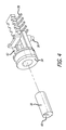
- Fig. 3A is an exploded view of the E-core assembly used in one embodiment for the module side of the connector.
- the exploded view is shown with the face of the E-core directed downward, though in the actual assembly the face of the E-core 28 would be directed outward beyond the edge of a printed circuit board in the module, with cover 34 covering most of the E-core.
- the center leg 36 of the E-core passes through winding bobbin 38 on member 40 which in turn has a number of electrical contacts or terminals 42 around the edge thereof. These terminals, when soldered to a printed circuit board in the module, become the support for the assembly and also act as the terminals to which the leads on the wire wound coil on bobbin 38 are connected.
- a single coil with multiple taps on the coil is typically used to provide various AC voltage outputs which then are converted to associated DC voltages as typically required for operation of a module.
- the planar and wire wound windings might be instead placed around the outer legs, though this is not preferred, as it does not package as well as the single winding around the center legs.
- member 40 is assembled thereto and the center leg 36 of E-core 28 is inserted through the center of bobbin 38. Also a spring 46 is compressed against member 44 and temporarily held in the compressed state by a thin blade inserted through slot 48 in cover 34 so that the cover 34 with compressed spring 46 may be placed over the assembly comprising E-core 28, bobbin 38 and member 40. Then the spring 46 is released so that the spring will encourage E-core 28 away from member 44, yet will allow E-core 28 some movement, relative to the bobbin, against the force of the spring 46 when it contacts the associated E-core on the backplane through the protective layers over the face of each E-core.
- a very thin protective coating may be put over the E-core if desired, at least all except the outward extending face of the E-core, such as, by way of example, by dipping the E-core in a very thin epoxy or other binder.
- the assembly of cover 34 with compressed spring 46 to the rest of the assembly shown in Fig. 3A may be done before terminals 42 are soldered to the printed circuit board in the module, or alternatively, after the assembly of E-core 28 and bobbin 38 in member 40 with terminals 42 thereon.
- pins 50 on member 40 extend into holes in the printed circuit board in the module to provide accurate alignment of the assembly with the circuit board 26 without relying on the soldered terminals 42 for positioning the assembly.
- the winding bobbin 54 on a support 52 for the I-cores 30 may be seen.
- two I-cores end to end do not make a complete magnetic circuit, but instead depend on completion of the magnetic circuit (a return path) through air or non-magnetic materials surrounding the I-cores. Consequently because part of the magnetic circuit is made up of non magnetic materials anyway, communication through the I-cores is not nearly as sensitive to the gap between the respective pair of I-cores as is power transfer through the gap between the power transferring E-cores during operation of the connector.
- a plastic member 52 is molded with an integral winding bobbin 54 and locating pin 56 with conductors 58 being either molded in or attached thereto.
- the pin 56 like pins 50 of Fig. 3A , provide a locating reference relative to a corresponding hole in the printed circuit board with terminals or supporting feet 58 providing mounting support much like terminals 42 of Fig. 3A .
- terminals or supporting feet 58 providing mounting support much like terminals 42 of Fig. 3A .
- multiple terminals 58 are shown, most are simply used for support, as unlike the secondary on the E-cores which typically has multiple taps, a single coil without taps is used for the secondary winding on the I-cores 30.
- the I-core 30 is cemented into member 52 with the end 60 being flush with the face of the bobbin 54.
- Fig. 5 is a perspective view of a module connector E-core and I-core assemblies on an edge of a circuit board in the module
- Fig. 6 is a view of the connector edge of the module without the protective layer over the assembly so as to illustrate the arrangement of the E-core and I-core assemblies, which assemblies are not visible with the protective layer in place.
- protective layer in one embodiment is another 0.005 inch thick Lexan sheet fastened in position around its edges to a floating support, which leaves sufficient flexibility for the application.
- the mounting screw holes surrounded by projections 62 which fit into corresponding holes in the backplane assembly for accurately locating the module on the backplane assembly. Projection 62 and the holes in the backplane assembly may be the same, or may be purposely made of different shapes or diameters, etc. to prevent mounting the module backward or upside down.
- Figs. 7 and 8 The final assembly of an exemplary embodiment is illustrated in Figs. 7 and 8 .
- Fig. 7 is an exploded view of the backplane assembly comprising the backplane circuit board 26 with the E-cores 28 and I-cores 30 thereon, the backplane rails 66 and cover 68 protecting the back of the backplane circuit board 26.
- Fig. 8 shows a module 64 mounted in slot 4 of the backplane assembly by screws 69.
- the label 32 covers the backplane circuit board 26 and identifies the slots by number.
- E-cores and I-cores were used for the coupling of power and signals, respectively.
- the use of I-cores is highly desirable for signals, as they perform well at the high frequencies used for signal transmission (preferably using Manchester or other coding having a zero DC value), and package compactly in a final connector assembly, though other shaped cores could be used if desired.
- C-cores such as shown in schematic form in Fig. 3B .
- planar windings on the backplane and the wire wound windings 38 on the module connector are on both legs of the C-cores 29, though these windings 38 could be on one leg only. If such windings were on one leg only, they should be on the same leg, not on opposite legs, to minimize flux leakage. Otherwise the assemblies are as described herein.
- shielding is best provided by conductive enclosures rather than magnetic enclosures, particularly for the I-cores.
- Such conductive enclosures may be provided, for example, by aluminum stampings or metal plated plastic enclosures.
- any such shielding should be spaced somewhat away from the I-cores so as to not choke off that space, but instead only contain the much lower flux density that would otherwise extend outward in significant strength over greater distances.
- the planar windings for the I-cores on the backplane circuit board include a grounded ring encircling the face of each respective I-core, but spaced outward to allow space for the flux as described.
- electromagnetic connectors using two E-cores assemblies and three I-core assemblies are shown.
- the E-core assemblies are essentially identical, one serving as the primary source of power for the module and the other serving as a backup source of power for the module.
- the three I-core assemblies one provides communication from the backplane to the module, one provides communication from the module to the backplane, and one provides a lower frequency bidirectional communication for such purposes as monitoring and supervisory functions.
- the use of two electromagnetic power transfer assemblies and three electromagnetic communication assemblies is application dependent, and fewer or more such assemblies may be used as required.
- the slot is periodically pinged when a module is not present by very temporarily powering the slot (an E-core primary planar winding or both E-core primary windings) and sensing the apparent inductance or impedance of the primary planar winding. If no module is present, the inductance will be very low, and the impedance will also be very low, not much more than the resistance of the respective E-core planar winding.
- the presence of a module may be sensed, even in the presence of a shorted wire wound secondary on one of the E-cores in the module (or backplane), or an open primary on one of the E-core planar windings by sensing no current when pinged, allowing disabling of the affected C-core pair, flagging the failure and continuing operation of the module using the other pair of E-cores for powering the module.
- Removal (or certain failures) of a module may be similarly detected by detecting a planar primary of one or both E-cores that is above the maximum allowed for a properly functioning module properly mounted to the backplane.
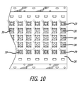
- Fig. 9 is an illustration of the rear of a module using C-cores 29 for the power connection of the connector
- Fig. 10 is an illustration of a backplane using corresponding C-cores 29, in both cases the C-cores replacing the E-cores 28.
- E-core is used herein and in the claims in a general sense to mean a magnetic core that has a cross section in the form of an E. This definition covers not only the E-core configuration shown herein, but also cores having a configuration of a surface of revolution or partial surface of revolution generated by rotating an E-core about the axis of its center leg.
- E-core would have to have an outer edge interrupted to allow the planar windings on the backplane to extend into the space between the center and the rim of the surface of revolution and to allow the exit of the wires on the windings in the module, but otherwise would function properly.
- the symmetry of the I-cores and the E-cores or C-cores allows the module to be assembled into a slot on the backplane with either orientation.
- the module is comprised to two identical circuits to provide a backup circuit if the one being used fails, or for both to operate so that a failure can be detected by the two having different results. Either way, the center I-core assembly can be used to talk to the module, and the other 2 I-core assemblies used for the module to talk to the backplane. Because of the symmetry, it doesn't matter which circuit is to talk to the backplane through which of the two I-core assemblies.
- circuitry in the module is not symmetrical, when the presence of a module is detected on insertion of a module, the module needs to be pinged for the module to identify itself.
- Incorporated in that circuitry and process can be a detection of a response tailored to identify the module orientation, after which the circuitry in the module or coupled to the backplane may reroute power and/or signals as appropriate.
Landscapes
- Engineering & Computer Science (AREA)
- Power Engineering (AREA)
- Manufacturing & Machinery (AREA)
- Coils Or Transformers For Communication (AREA)
- Details Of Connecting Devices For Male And Female Coupling (AREA)
Abstract
Description
- The present invention relates to the field of electrical connectors.
- The preferred embodiments of the present invention are used as connectors between backplanes and modules mounted on the backplanes, and accordingly the prior art relating to such connectors will be discussed. However it is to be understood that use of the present invention is not so limited, and the invention may be adapted for as wide range of use.
- Electrical connectors of various sizes and configurations are well known in the art. Multiple pin connectors usually use a multiple pin male connector member that plugs into a female receptacle, with the electrical connections depending on direct metal to metal contact to complete the circuits. For most applications, connectors of this type are satisfactory, though can cause connection failures on initial installation by pin bending on the male connector, or over a period of time as dirt and corrosion build up.
- For high reliability applications and in harsh environments, such as for under water use, high humidity and dusty or dirty environments, typically the connector housings are round and include an alignment feature plus a rotary collar on one connector member that screws onto the other connector member to maintain positive engagement of the connector members, with an 0-ring providing the ultimate seal of the pins and sockets in the connector.
- However, in some instances, physical constraints and other considerations prevent the use of such an O-ring sealed connector. One such application of connectors is in backplane applications wherein a relatively large number of boards or modules must be "plugged" into a backplane, typically side by side with very little space between them. In that regard, as used herein, unless the context indicates otherwise, a backplane is a printed circuit board into which boards or modules are "plugged", which backplane printed circuit board provides power to and/or communication with the module or printed circuit mounted on the backplane printed circuit board, or the entire assembly that includes such a backplane printed circuit board.
- A simple edge connector is adequate for applications wherein one can be assured that the environment will not be hostile. For applications that require high reliability and lack of a harsh environment cannot be assured, such as in industrial process control applications, circuit failure detection techniques and/or error detection and correction techniques are commonly used, as is redundancy in circuitry to provide high reliability in circuit operation over long periods of time. However, corrosion is a persistent problem and may render an initially good contact nonfunctional, as such assemblies may sit almost indefinitely without attention until a failure does occur. Therefore conventional connectors remain a weak link in the overall system.
-
-
Fig. 1 illustrates a section of a backplane circuit board in accordance with one embodiment of the present invention. -
Fig. 2 illustrates a section of the circuit board ofFig. 1 with E-cores and I-cores placed therein. -
Fig. 3A is an exploded view of the E-core assembly used in one embodiment for the module side of the connector. -
Fig. 3B schematically illustrates the use of C-cores for the E-cores in the assembly ofFig. 3A . -
Fig. 4 illustrates the winding bobbin on a support for the I-cores. -
Fig. 5 is a perspective view of a module connector E-core and I-core assemblies on an edge of a circuit board in the module. -
Fig. 6 is a view of the connector edge of the module without the protective layer over the assembly so as to illustrate the arrangement of the E-core and I-core assemblies. -
Fig. 7 is a view of the connector edge of the module without the protective layer over the assembly so as to illustrate the arrangement of the E-core and I-core assemblies. -
Fig. 8 shows a module mounted by screws in a slot of the backplane assembly. -
Fig. 9 is an illustration of the rear of a module using C-cores for the power connection of the connector. -
Fig. 10 is an illustration of a backplane using C-cores for the power connection of the connector. - In the description to follow, exemplary embodiments for electrically connecting modules to backplanes are described, though the invention is also suitable for many other uses.
- In that description, references are made to primary windings and secondary windings. As a matter of convention, when references are made to primary and secondary windings, a primary winding refers to a winding on the backplane, whereas a secondary winding is a winding in the module. In the case of power transfer, this convention is traditional. However in the case of signal transfer, this convention may or may not be traditional, depending on the direction of the signaling, and in the case of bidirectional signaling, is arbitrary. Further, the word module as used herein is used in a most general sense.
- Referring to
Fig. 1 , a section of abackplane circuit board 26 in accordance with one embodiment of the present invention may be seen. In accordance with that Figure, a typicalbackplane circuit board 26 in accordance with this embodiment will have a plurality of openings orholes 20 there through, each for the receipt of an I-core during assembly of the backplane, together with one or more groups ofopenings - An I-core of the type preferably used will be in the form of a round cylindrical slug of magnetic material, in a preferred embodiment a ferrite suitable for use at high frequencies. The E-cores of a typical embodiment will be conventional E-cores, in the embodiment being described, also ferrite E-cores which may be the same grade of ferrite or a different grade of ferrite than the I-cores. In that regard, the E-core devices are used for the transfer of power to a module "plugged" into the backplane using a connector in accordance with an embodiment of the present invention, whereas the I-core devices are used for communication purposes. Accordingly, preferably the E-core ferrite (or other material) will be selected for its relatively high saturation density for best power transfer, whereas the I-core ferrite (or other material) will be selected for its high frequency capabilities to assure maximum signal communication bandwidth. Consequently, one aspect of this invention is the separation of the power and signal transfer rather than trying to transfer power and signals in a single magnetic device, and also the optional use of different magnetic materials, preferably the use of different grades of ferrite, for the power and signal transfer devices to allow maximizing the performance of each.
- The
backplane circuit board 26 ofFig. 1 will typically be a multilayer board with planar (printed)windings core opening 20 or the center opening 22 of anE-core opening group conductive traces 25 of opposite winding sense on alternate layers of the multilayered printedcircuit board 26 and then by connecting the inner ends of the conductive traces of the first and second layers, the outer ends of the conductive traces on the second and third layers, etc. This forms a series connection of the conductive traces on multiple layers, all effectively acting with the same winding sense as interconnected. Such interconnection may be by way of example by the use of plated through holes at different locations (angles) around the inner and outer peripheries of the windings. Alternatively, the interconnector may be made as between alternate board layers as the multilayer circuit board is fabricated. By using such a winding, the total number of turns that may be achieved, while less than a typical wire wound coil, can still be substantial. Of course alternatively, for the E-cores, the planar windings could be around either or bothregions 24, or around bothregions - Now referring to
Fig. 2 , a section of thecircuit board 26 withE-cores 28 and I-cores 30 placed therein. In one embodiment, alabel 32 with an adhesive on the top surface thereof is placed under thecircuit board 26 and theE-cores 28 and I-cores 30 are placed in position in theboard 32 by a typical pick-and-place machine, with the E-cores and I-cores strongly adhering to the adhesive side of thelabel 32. In that regard, the openings in the printedcircuit board 26 are slightly larger than theE-cores 28 and I-cores 30 so as to leave some gap around the cores for subsequent filling by an appropriate potting compound. The potting compound may be a hard potting compound such as an epoxy or alternatively may be a flexible potting compound such as a silicon rubber. A silicon rubber will provide some flexibility between theE-cores 28 and I-cores 30 and the backplane printedcircuit board 26, if needed. However such flexibility may not be needed in that the combination of the printed circuit board and a rigid potting material makes the printed circuit board very rigid to avoid backplane flexing. Also the backplane printed circuit board will not be subject to the relatively high forces of prior art backplane printed circuit boards because of the absence of any high forces thereon required for full prior art connector engagement, though vibration may be encountered in some applications. In the claims to follow, materials such a epoxy and silicon rubber are considered positive mounts for the respective cores because they hold the cores in place, as opposed to being spring mounted to accommodate meaningful deflection under force. - Of course once completed, the assembled backplane printed
circuit board 26 will in turn become part of a larger assembly forming some part of a support chassis which may vary considerably, depending on the application. In the present invention, the E-cores 28 on the backplane printed circuit board 26 (Fig. 2 ) meet with a respective E-core in a module to be connected to the backplane. Since in preferred embodiments such E-cores are used for the transfer of AC power from the backplane to a module mounted on the backplane, highly efficient energy transfer from the primaryplanar windings 25 on the backplane multilayer printedcircuit board 26 to the wire windings on the E-cores in the module requires a minimum gap in the magnetic circuit formed by that E-core pair. This in turn requires a minimum gap (minimum non-magnetic spacing) between the E-cores 28 on the printedcircuit board 26 and the respective E-cores in the module connector, except as required by the protection for the E-cores 28 provided by thelabel 32 on the backplane printedcircuit board 26 and by similar protection for the complementary E-cores in a module. In one embodiment, thelabel 32 is a 0.005 inch Lexan label on the backplane printedcircuit board 26 and a corresponding Lexan member protecting the E-cores in the module. Note that a 0.005 inch protection of each leg of each E-core itself causes a 0.020 gap in the magnetic circuit formed by an E-core pair. If the E-cores in both the backplane printedcircuit board 26 and in the module were positively fixed in position, that would require providing extra spacing to allow for a variation in that fixed position, both initially and due to thermal expansion and warpage effects that might be caused by heat generated in the module. Accordingly in accordance with some embodiments of the present invention, the E-cores in the module connector are spring loaded so as to slightly protrude from the mounting plane of the module to lie flat against the respective E-cores on the backplane printed circuit board 26 (of course with their protective layers there between) with the spring depressing as required when the module is located in its final position. This spring loading assures a constant minimum gap defined by the protective layers over the E-cores in spite of the differential expansion, warpage in the assembly, vibration, etc., yet very much limits the pressure on the E-cores regardless of such factors. -
Fig. 3A is an exploded view of the E-core assembly used in one embodiment for the module side of the connector. For purposes of illustration, the exploded view is shown with the face of the E-core directed downward, though in the actual assembly the face of the E-core 28 would be directed outward beyond the edge of a printed circuit board in the module, withcover 34 covering most of the E-core. Thecenter leg 36 of the E-core passes through windingbobbin 38 onmember 40 which in turn has a number of electrical contacts orterminals 42 around the edge thereof. These terminals, when soldered to a printed circuit board in the module, become the support for the assembly and also act as the terminals to which the leads on the wire wound coil onbobbin 38 are connected. In that regard, a single coil with multiple taps on the coil is typically used to provide various AC voltage outputs which then are converted to associated DC voltages as typically required for operation of a module. As an alternative, the planar and wire wound windings might be instead placed around the outer legs, though this is not preferred, as it does not package as well as the single winding around the center legs. - After bobbin 38 is wound,
member 40 is assembled thereto and thecenter leg 36 of E-core 28 is inserted through the center ofbobbin 38. Also aspring 46 is compressed againstmember 44 and temporarily held in the compressed state by a thin blade inserted throughslot 48 incover 34 so that thecover 34 with compressedspring 46 may be placed over the assembly comprising E-core 28,bobbin 38 andmember 40. Then thespring 46 is released so that the spring will encourage E-core 28 away frommember 44, yet will allow E-core 28 some movement, relative to the bobbin, against the force of thespring 46 when it contacts the associated E-core on the backplane through the protective layers over the face of each E-core. While such movement is not substantial and bobbins are typically not abrasive, a very thin protective coating may be put over the E-core if desired, at least all except the outward extending face of the E-core, such as, by way of example, by dipping the E-core in a very thin epoxy or other binder. - The assembly of
cover 34 with compressedspring 46 to the rest of the assembly shown inFig. 3A may be done beforeterminals 42 are soldered to the printed circuit board in the module, or alternatively, after the assembly of E-core 28 andbobbin 38 inmember 40 withterminals 42 thereon. In that regard, pins 50 onmember 40 extend into holes in the printed circuit board in the module to provide accurate alignment of the assembly with thecircuit board 26 without relying on the solderedterminals 42 for positioning the assembly. - Now referring to
Fig. 4 , the windingbobbin 54 on asupport 52 for the I-cores 30 may be seen. In the case of the I-cores, two I-cores end to end do not make a complete magnetic circuit, but instead depend on completion of the magnetic circuit (a return path) through air or non-magnetic materials surrounding the I-cores. Consequently because part of the magnetic circuit is made up of non magnetic materials anyway, communication through the I-cores is not nearly as sensitive to the gap between the respective pair of I-cores as is power transfer through the gap between the power transferring E-cores during operation of the connector. Therefore the I-cores 30 in the connector in the module are positively mounted to the circuit board in the module to always provide some gap between the I-cores beyond that provided by the protective layers over the adjacent ends thereof to prevent them from ever interfering with each other when a module is mounted to the backplane. Accordingly as shown inFig. 4 , aplastic member 52 is molded with an integral windingbobbin 54 and locatingpin 56 withconductors 58 being either molded in or attached thereto. - The
pin 56, likepins 50 ofFig. 3A , provide a locating reference relative to a corresponding hole in the printed circuit board with terminals or supportingfeet 58 providing mounting support much liketerminals 42 ofFig. 3A . In that regard, whilemultiple terminals 58 are shown, most are simply used for support, as unlike the secondary on the E-cores which typically has multiple taps, a single coil without taps is used for the secondary winding on the I-cores 30. - Once the
bobbin 54 is wound, the I-core 30 is cemented intomember 52 with theend 60 being flush with the face of thebobbin 54. -
Fig. 5 is a perspective view of a module connector E-core and I-core assemblies on an edge of a circuit board in the module, andFig. 6 is a view of the connector edge of the module without the protective layer over the assembly so as to illustrate the arrangement of the E-core and I-core assemblies, which assemblies are not visible with the protective layer in place. In that regard, such protective layer in one embodiment is another 0.005 inch thick Lexan sheet fastened in position around its edges to a floating support, which leaves sufficient flexibility for the application. Also visible inFig. 6 are the mounting screw holes surrounded byprojections 62 which fit into corresponding holes in the backplane assembly for accurately locating the module on the backplane assembly.Projection 62 and the holes in the backplane assembly may be the same, or may be purposely made of different shapes or diameters, etc. to prevent mounting the module backward or upside down. - The final assembly of an exemplary embodiment is illustrated in
Figs. 7 and8 .Fig. 7 is an exploded view of the backplane assembly comprising thebackplane circuit board 26 with the E-cores 28 and I-cores 30 thereon, the backplane rails 66 and cover 68 protecting the back of thebackplane circuit board 26.Fig. 8 shows amodule 64 mounted in slot 4 of the backplane assembly by screws 69. Thelabel 32 covers thebackplane circuit board 26 and identifies the slots by number. - In the embodiment hereinbefore described, E-cores and I-cores were used for the coupling of power and signals, respectively. The use of I-cores is highly desirable for signals, as they perform well at the high frequencies used for signal transmission (preferably using Manchester or other coding having a zero DC value), and package compactly in a final connector assembly, though other shaped cores could be used if desired. For the E-cores, another alternative would be to use C-cores, such as shown in schematic form in
Fig. 3B . Here the planar windings on the backplane and thewire wound windings 38 on the module connector are on both legs of the C-cores 29, though thesewindings 38 could be on one leg only. If such windings were on one leg only, they should be on the same leg, not on opposite legs, to minimize flux leakage. Otherwise the assemblies are as described herein. - In the foregoing description, nothing has been said about shielding to prevent crosstalk between communication channels or electromagnetic radiation in general, though shielding is desirable, if not required. Because of the frequencies typically used for electromagnetic connectors in accordance with the present invention, shielding is best provided by conductive enclosures rather than magnetic enclosures, particularly for the I-cores. Such conductive enclosures may be provided, for example, by aluminum stampings or metal plated plastic enclosures. For the I-cores, since the magnetic circuit partially defined by the I-cores is completed by the nonmagnetic space around the I-cores, any such shielding should be spaced somewhat away from the I-cores so as to not choke off that space, but instead only contain the much lower flux density that would otherwise extend outward in significant strength over greater distances. As part of that shielding, the planar windings for the I-cores on the backplane circuit board include a grounded ring encircling the face of each respective I-core, but spaced outward to allow space for the flux as described.
- Also in the foregoing description, electromagnetic connectors using two E-cores assemblies and three I-core assemblies are shown. In this exemplary embodiment, the E-core assemblies are essentially identical, one serving as the primary source of power for the module and the other serving as a backup source of power for the module. For the three I-core assemblies, one provides communication from the backplane to the module, one provides communication from the module to the backplane, and one provides a lower frequency bidirectional communication for such purposes as monitoring and supervisory functions. Obviously the use of two electromagnetic power transfer assemblies and three electromagnetic communication assemblies is application dependent, and fewer or more such assemblies may be used as required.
- One aspect of a practical embodiment is the detection of the presence or absence of a module in a particular "slot" on the backplane. Obviously a switch on the backplane could be used, though in general this would not be allowed, and further would itself constitute a failure prone component in what would and should be a high reliability connector. Instead, in one embodiment, the slot is periodically pinged when a module is not present by very temporarily powering the slot (an E-core primary planar winding or both E-core primary windings) and sensing the apparent inductance or impedance of the primary planar winding. If no module is present, the inductance will be very low, and the impedance will also be very low, not much more than the resistance of the respective E-core planar winding. By pinging both E-core primary windings, the presence of a module may be sensed, even in the presence of a shorted wire wound secondary on one of the E-cores in the module (or backplane), or an open primary on one of the E-core planar windings by sensing no current when pinged, allowing disabling of the affected C-core pair, flagging the failure and continuing operation of the module using the other pair of E-cores for powering the module. Removal (or certain failures) of a module may be similarly detected by detecting a planar primary of one or both E-cores that is above the maximum allowed for a properly functioning module properly mounted to the backplane.
-
Fig. 9 is an illustration of the rear of a module using C-cores 29 for the power connection of the connector, andFig. 10 is an illustration of a backplane using corresponding C-cores 29, in both cases the C-cores replacing the E-cores 28. In that regard, it is to be noted that the term E-core is used herein and in the claims in a general sense to mean a magnetic core that has a cross section in the form of an E. This definition covers not only the E-core configuration shown herein, but also cores having a configuration of a surface of revolution or partial surface of revolution generated by rotating an E-core about the axis of its center leg. Any such E-core would have to have an outer edge interrupted to allow the planar windings on the backplane to extend into the space between the center and the rim of the surface of revolution and to allow the exit of the wires on the windings in the module, but otherwise would function properly. - In some embodiments, the symmetry of the I-cores and the E-cores or C-cores allows the module to be assembled into a slot on the backplane with either orientation. By way of example, in some embodiments, the module is comprised to two identical circuits to provide a backup circuit if the one being used fails, or for both to operate so that a failure can be detected by the two having different results. Either way, the center I-core assembly can be used to talk to the module, and the other 2 I-core assemblies used for the module to talk to the backplane. Because of the symmetry, it doesn't matter which circuit is to talk to the backplane through which of the two I-core assemblies. Even if the circuitry in the module is not symmetrical, when the presence of a module is detected on insertion of a module, the module needs to be pinged for the module to identify itself. Incorporated in that circuitry and process can be a detection of a response tailored to identify the module orientation, after which the circuitry in the module or coupled to the backplane may reroute power and/or signals as appropriate.
- Thus the present invention has a number of aspects, which aspects may be practiced alone or in various combinations or sub-combinations, as desired. While certain preferred embodiments of the present invention have been disclosed and described herein for purposes of illustration and not for purposes of limitation, it will be understood by those skilled in the art that various changes in form and detail may be made therein without departing from the spirit and scope of the invention as defined by the full breadth of the following claims.
Claims (27)
- A connector for transferring power from a backplane to a module mounted on the backplane comprising:a first magnetic E-core having a center leg and first and second outer legs, the center leg and the outer legs being joined at a first end thereof and being mounted with a second end thereof extending into openings in the backplane, the backplane having a printed coil encircling at least one of the three legs;a second magnetic E-core having a center leg and first and second outer legs, the center leg and the outer legs being joined at one end thereof and being mounted with a second end thereof mounted adjacent an end of the module, the module having at least one wound coil encircling at least one of the three legs;the backplane and the module being configured so that the second end of each leg of the magnetic E-core on the backplane is aligned with the corresponding leg of the magnetic E-core in the module when the module is mounted to the backplane.
- A connector for transferring power from a backplane to a module mounted on the backplane comprising:a first magnetic C-core having first and second legs, the first and second legs being joined at a first end thereof and being mounted with a second end thereof extending into openings in the backplane, the backplane having a printed coil encircling at least one of the first and second legs;a second magnetic C-core having first and second legs, the first and second legs being joined at one end thereof and being mounted with a second end thereof mounted adjacent an end of the module, the module having at least one wire wound coil encircling at least one of the first and second legs;the backplane and the module being configured so that the second end of each leg of the magnetic C-core on the backplane is aligned with the corresponding leg of the magnetic C-core in the module when the module is mounted to the backplane.
- The connector of claim 1 or claim 2 wherein the wound coil in the module is a coil with multiple taps.
- The connector of any of claims 1 to 3 wherein the second ends of the magnetic E-core or magnetic C-core in the backplane do not protrude from the module side of the backplane.
- The connector of claim 4 wherein the second ends of each of the first and second magnetic E-cores or magnetic C-cores have a protective sheet or layer thereover.
- The connector of claim 4 wherein the magnetic E-core or magnetic C-core in the module is spring mounted to provide a spring force between the magnetic E-core or magnetic C-core in the module and the magnetic E-core or magnetic C-core in the backplane when the module is mounted to the backplane.
- The connector of any one of claims 1 to 6, also for signal transmission for at least one of a backplane to a module mounted on the backplane, and a module to a backplane to which the module is mounted, further comprising:first and second magnetic I-cores;the first magnetic I-core being mounted with an end thereof extending into an opening in the backplane, the backplane having a printed coil encircling the first magnetic I-core;the second magnetic I-core having an end thereof mounted adjacent an end of the module, the module having at least one wound coil encircling the second magnetic I-core;the backplane and the module also being configured so that the end of the first magnetic I-core is adjacent the end of the second magnetic I-core when the module is mounted to the backplane.
- The connector of claim 7 wherein the connector further comprises:at least third and fourth magnetic E-cores or magnetic C-cores, the third magnetic E-core or magnetic C-core being configured on the backplane like the first magnetic E-core or magnetic C-core and the fourth magnetic E-core or magnetic C-core being mounted adjacent the end of the module and configured like the second magnetic E-core or magnetic C-core;at least third and fourth magnetic I-cores, the third magnetic I-core being configured on the backplane like the first magnetic I-core and the fourth magnetic I-core being mounted adjacent the end of the module and configured like the second magnetic I-core;the first and second magnetic E-cores or magnetic C-cores being mounted symmetrically with the third and fourth magnetic E-cores or magnetic C-cores about a center of the module;the first and second magnetic I-cores being mounted symmetrically with the third and fourth magnetic I-cores about a center of the module;whereby the connector will be functional when the module may be mounted to the backplane in a first relative orientation, or a second relative orientation reversed from the first relative orientation.
- The connector of claim 8 wherein the module contains two identical circuits.
- The connector of claim 8 wherein the module connected to the backplane includes circuitry for sensing the relative orientation of the module and rerouting power and/or signals as needed.
- The connector of any of claims 7 to 10 wherein the end of the first magnetic I-core in the backplane does not protrude from the module side of the backplane.
- The connector of any of claims 7 to 11 wherein the ends of each of the magnetic I-cores have a protective sheet or layer thereover.
- The connector of any of claims 7 to 12 wherein the magnetic I-cores in the module and in the backplane are positively mounted in the module and the backplane, respectively.
- The connector of claim 13 wherein the magnetic I-core in the backplane is mounted in the backplane with an axis of the magnetic I-core perpendicular to the backplane, and wherein the magnetic I-core in the module is mounted with an axis substantially collinear with the axis of the magnetic I-core in the backplane when the module is mounted to the backplane.
- The connector of claim 14 wherein the magnetic I-cores are mounted so that when the module is mounted to the backplane, the ends of the magnetic I-cores are in close proximity without subjecting each other to a mechanical force along their axes.
- The connector of any of claims 7 to 15 wherein the magnetic I-cores are ferrite I-cores.
- The connector of any of claims 7 to 16 wherein the magnetic E-cores or magnetic C-cores and the magnetic I-cores are ferrite cores, the magnetic E-cores or magnetic C-cores being of one grade of ferrite and the magnetic I-cores being of a second grade of ferrite different from the first grade.
- The connector of any of claims 1 to 17 wherein the magnetic E-cores or magnetic C-cores are ferrite E-cores or ferrite C-cores, respectively.
- A method of coupling power from a backplane to a module to be coupled to the backplane comprising:mounting a first magnetic C-core or E-core on a backplane circuit board with faces thereof extending into openings in the backplane, the backplane circuit board having at least one planar coil in the backplane circuit board encircling at least one leg of the first magnetic C-core or E-core;providing a second magnetic C-core or E-core mounted in a module with faces thereof adjacent a module surface, the second magnetic C-core or E-core having a wire wound coil encircling at least one leg of the second magnetic C-core or E-core;whereby when the module is coupled to the backplane, the faces of the second magnetic C-core or E-core on the module will be adjacent to the faces of the first magnetic C-core or E-core on the backplane circuit board, AC electrical power may be applied to the planar coil and coupled to the wire wound coil.
- The method of claim 19 wherein the wire wound coil on the second magnetic C-core or E-core and/or the second ends of the second magnetic C-core or E-core are as defined in any of claims 3 to 5.
- The method of claim 19 further comprising spring mounting the second magnetic C-core or E-core in the module to provide a spring force between the first magnetic C-core or E-core in the module and the second magnetic C-core or E-core in the backplane when the module is mounted to the backplane; and wherein the second ends of the second magnetic C-core or E-core are as defined in claim 4.
- The method of any of claims 19 to 21, also for signal transmission for at least one of a backplane to a module mounted on the backplane, and a module to a backplane to which the module is mounted, further comprising:providing first and second magnetic I-cores;mounting the first magnetic I-core with an end thereof passing through an opening in the backplane, the backplane having a printed coil encircling the first magnetic I-core;mounting the second magnetic I-core with an end thereof adjacent an end of the module with the second magnetic I-core having at least one wound coil encircling the second magnetic I-core and so that the end of the first magnetic I-core is adjacent the end of the second magnetic I-core when the module is mounted to the backplane.
- The method of claim 22 further comprises:providing at least third and fourth magnetic I-cores;configuring the third magnetic E-core like the first magnetic I-core and the fourth magnetic E-core like the second magnetic I-core;providing at least third and fourth magnetic I-cores;configuring the third magnetic I-core like the first magnetic I-core and the fourth magnetic I-core like the second magnetic I-core;mounting the third and fourth magnetic C-cores or E-cores symmetrically with the first and second magnetic C-cores or E-cores about a center of the module;mounting the third and fourth magnetic I-cores symmetrically with the first and second magnetic I-cores about a center of the module;whereby the module will be functional when the module is mounted to the backplane in a first relative orientation, or a second relative orientation reversed from the first relative orientation.
- The method of claim 22 or claim 23 wherein the module, the magnetic I-cores, the magnetic E-cores and/or the magnetic C-cores are as defined in any of claims 9 to 18.
- A connector for signal transmission for at least one of a backplane to a module mounted on the backplane, and a module to a backplane to which the module is mounted, comprising:first and second magnetic I-cores;the first magnetic I-core being mounted with an end thereof passing into an opening in the backplane, the backplane having a printed coil encircling the first magnetic I-core;the second magnetic I-core having an end thereof mounted adjacent an end of the module, the module having at least one wound coil encircling the second magnetic I-core;the backplane and the module also being configured so that the end of the first magnetic I-core is adjacent the end of the second magnetic I-core when the module is mounted to the backplane.
- The connector of claim 25 wherein the connector further comprises:at least third and fourth magnetic I-cores, the third magnetic I-core being configured on the backplane like the first magnetic I-core and the fourth magnetic I-core being mounted adjacent the end of the module and configured like the second magnetic I-core;the first and second magnetic I-cores being mounted symmetrically with the third and fourth magnetic I-cores about a center of the module;whereby the connector will be functional when the module may be mounted to the backplane in a first relative orientation, or a second relative orientation reversed from the first relative orientation.
- The connector of claim 25 or claim 26 wherein the module and/or the I-cores are as defined in any of claims 9 to 16.
Applications Claiming Priority (1)
| Application Number | Priority Date | Filing Date | Title |
|---|---|---|---|
| US13/875,858 US9449756B2 (en) | 2013-05-02 | 2013-05-02 | Electromagnetic connectors |
Publications (3)
| Publication Number | Publication Date |
|---|---|
| EP2811496A2 true EP2811496A2 (en) | 2014-12-10 |
| EP2811496A3 EP2811496A3 (en) | 2015-01-28 |
| EP2811496B1 EP2811496B1 (en) | 2019-04-24 |
Family
ID=50677997
Family Applications (2)
| Application Number | Title | Priority Date | Filing Date |
|---|---|---|---|
| EP14791210.9A Active EP2992572B1 (en) | 2013-05-02 | 2014-05-01 | Electromagnetic connectors |
| EP14166908.5A Active EP2811496B1 (en) | 2013-05-02 | 2014-05-02 | Electromagnetic connectors |
Family Applications Before (1)
| Application Number | Title | Priority Date | Filing Date |
|---|---|---|---|
| EP14791210.9A Active EP2992572B1 (en) | 2013-05-02 | 2014-05-01 | Electromagnetic connectors |
Country Status (5)
| Country | Link |
|---|---|
| US (1) | US9449756B2 (en) |
| EP (2) | EP2992572B1 (en) |
| JP (2) | JP6585334B2 (en) |
| CN (2) | CN104134512B (en) |
| WO (1) | WO2014179566A1 (en) |
Families Citing this family (25)
| Publication number | Priority date | Publication date | Assignee | Title |
|---|---|---|---|---|
| US9600434B1 (en) | 2011-12-30 | 2017-03-21 | Bedrock Automation Platforms, Inc. | Switch fabric having a serial communications interface and a parallel communications interface |
| US10834094B2 (en) | 2013-08-06 | 2020-11-10 | Bedrock Automation Platforms Inc. | Operator action authentication in an industrial control system |
| US12061685B2 (en) | 2011-12-30 | 2024-08-13 | Analog Devices, Inc. | Image capture devices for a secure industrial control system |
| US9727511B2 (en) | 2011-12-30 | 2017-08-08 | Bedrock Automation Platforms Inc. | Input/output module with multi-channel switching capability |
| US8862802B2 (en) | 2011-12-30 | 2014-10-14 | Bedrock Automation Platforms Inc. | Switch fabric having a serial communications interface and a parallel communications interface |
| US10834820B2 (en) | 2013-08-06 | 2020-11-10 | Bedrock Automation Platforms Inc. | Industrial control system cable |
| US8971072B2 (en) | 2011-12-30 | 2015-03-03 | Bedrock Automation Platforms Inc. | Electromagnetic connector for an industrial control system |
| US9449756B2 (en) * | 2013-05-02 | 2016-09-20 | Bedrock Automation Platforms Inc. | Electromagnetic connectors |
| US8868813B2 (en) | 2011-12-30 | 2014-10-21 | Bedrock Automation Platforms Inc. | Communications control system with a serial communications interface and a parallel communications interface |
| US9467297B2 (en) | 2013-08-06 | 2016-10-11 | Bedrock Automation Platforms Inc. | Industrial control system redundant communications/control modules authentication |
| US9191203B2 (en) | 2013-08-06 | 2015-11-17 | Bedrock Automation Platforms Inc. | Secure industrial control system |
| US11314854B2 (en) | 2011-12-30 | 2022-04-26 | Bedrock Automation Platforms Inc. | Image capture devices for a secure industrial control system |
| US11967839B2 (en) | 2011-12-30 | 2024-04-23 | Analog Devices, Inc. | Electromagnetic connector for an industrial control system |
| US11144630B2 (en) | 2011-12-30 | 2021-10-12 | Bedrock Automation Platforms Inc. | Image capture devices for a secure industrial control system |
| US9437967B2 (en) | 2011-12-30 | 2016-09-06 | Bedrock Automation Platforms, Inc. | Electromagnetic connector for an industrial control system |
| US10613567B2 (en) | 2013-08-06 | 2020-04-07 | Bedrock Automation Platforms Inc. | Secure power supply for an industrial control system |
| USD721706S1 (en) * | 2013-08-06 | 2015-01-27 | Bedrock Automation Platforms Inc. | Input output module for an industrial control system |
| USD758978S1 (en) * | 2013-08-06 | 2016-06-14 | Bedrock Automation Platforms, Inc. | Backplane for an industrial control system (ICS) |
| USD721707S1 (en) * | 2013-08-06 | 2015-01-27 | Bedrock Automation Platforms Inc. | Communications control module for an industrial control system |
| CN105281061A (en) | 2014-07-07 | 2016-01-27 | 基岩自动化平台公司 | Industrial control system cable |
| EP3840168A1 (en) * | 2015-04-13 | 2021-06-23 | Bedrock Automation Platforms Inc. | Secure power supply for an industrial control system |
| JP6412051B2 (en) * | 2016-04-18 | 2018-10-24 | ファナック株式会社 | Automatic assembly system and method for improving the yield of automatic assembly of printed boards |
| JP2017208889A (en) * | 2016-05-16 | 2017-11-24 | 富士通株式会社 | Wireless power supply apparatus and wireless power supply method |
| CN107546012A (en) * | 2017-09-29 | 2018-01-05 | 佛山市中研非晶科技股份有限公司 | A kind of amorphous alloy oil immersion type transformer of noise reduction and anti-sudden short circuit |
| CN118786496A (en) * | 2022-04-21 | 2024-10-15 | 索尤若驱动有限及两合公司 | Secondary sections |
Family Cites Families (51)
| Publication number | Priority date | Publication date | Assignee | Title |
|---|---|---|---|---|
| JPS51131185A (en) | 1975-05-12 | 1976-11-15 | West Electric Co Ltd | Electronic scintillation device |
| JPS59177226A (en) | 1983-03-24 | 1984-10-06 | Kaneko Youshiyoku Sangyo Kk | Continuous feeding apparatus for granular articles |
| DE69119164T2 (en) * | 1990-08-31 | 1996-12-05 | Whitaker Corp | Couplers for data streams |
| US5469334A (en) | 1991-09-09 | 1995-11-21 | Power Integrations, Inc. | Plastic quad-packaged switched-mode integrated circuit with integrated transformer windings and mouldings for transformer core pieces |
| US5229652A (en) | 1992-04-20 | 1993-07-20 | Hough Wayne E | Non-contact data and power connector for computer based modules |
| JP3491931B2 (en) * | 1993-09-30 | 2004-02-03 | 日立マクセル株式会社 | Data transmitting / receiving apparatus and portable information recording medium used therefor |
| NO944266L (en) | 1993-11-15 | 1995-05-16 | Hughes Aircraft Co | Inductive charging system |
| JPH07320963A (en) * | 1994-05-19 | 1995-12-08 | Japan Aviation Electron Ind Ltd | Non-contact connector |
| JPH0837121A (en) * | 1994-07-26 | 1996-02-06 | Matsushita Electric Works Ltd | Power supply device |
| JP3426774B2 (en) * | 1995-03-03 | 2003-07-14 | 日立マクセル株式会社 | Electromagnetic coupling connector and method of manufacturing the same |
| US5958030A (en) | 1996-12-27 | 1999-09-28 | Nortel Networks Corporation | Intra-shelf free space interconnect |
| JPH1189103A (en) * | 1997-09-11 | 1999-03-30 | Sanyo Electric Co Ltd | Non-contact type charger |
| US6124778A (en) | 1997-10-14 | 2000-09-26 | Sun Microsystems, Inc. | Magnetic component assembly |
| US6009410A (en) | 1997-10-16 | 1999-12-28 | At&T Corporation | Method and system for presenting customized advertising to a user on the world wide web |
| JP3745151B2 (en) * | 1999-03-01 | 2006-02-15 | 三菱電機株式会社 | Non-contact transmission device |
| SE9903466D0 (en) | 1999-09-24 | 1999-09-24 | Siemens Elema Ab | Insulation transformer |
| WO2001073883A2 (en) | 2000-03-24 | 2001-10-04 | Cymbet Corporation | Low-temperature fabrication of thin-film energy-storage devices |
| WO2001080442A2 (en) | 2000-04-18 | 2001-10-25 | Schleifring Und Apparatebau Gmbh | Array for contactless transmission of electrical signals or energy |
| JP2002280238A (en) * | 2001-03-21 | 2002-09-27 | Yazaki Corp | Electromagnetic induction type connector |
| JP2002343655A (en) | 2001-05-18 | 2002-11-29 | Ishikawajima Harima Heavy Ind Co Ltd | Magnetic coupling connector for high voltage and large current |
| JP2002359131A (en) | 2001-05-31 | 2002-12-13 | Yazaki Corp | Electromagnetic induction type connector |
| DE10224526B8 (en) * | 2001-05-31 | 2006-10-19 | Yazaki Corp. | Electromagnetic induction connection |
| JP3628989B2 (en) | 2001-08-08 | 2005-03-16 | 東京パーツ工業株式会社 | Disc-shaped eccentric rotor and flat vibration motor having the same |
| US6936917B2 (en) | 2001-09-26 | 2005-08-30 | Molex Incorporated | Power delivery connector for integrated circuits utilizing integrated capacitors |
| JP2003142327A (en) * | 2001-10-31 | 2003-05-16 | Furukawa Electric Co Ltd:The | Non-contact power supply |
| US6988162B2 (en) | 2002-02-05 | 2006-01-17 | Force10 Networks, Inc. | High-speed router with single backplane distributing both power and signaling |
| US6812803B2 (en) | 2002-02-05 | 2004-11-02 | Force10 Networks, Inc. | Passive transmission line equalization using circuit-board thru-holes |
| EP1547222B1 (en) * | 2002-06-10 | 2018-10-03 | City University of Hong Kong | Planar inductive battery charger |
| WO2004055949A1 (en) | 2002-12-18 | 2004-07-01 | Pirelli & C. S.P.A. | Modular apparatus and method for data communication between a distribution network and a residential network |
| JP4753153B2 (en) * | 2005-07-27 | 2011-08-24 | ブラザー工業株式会社 | Wireless communication system |
| US7351066B2 (en) | 2005-09-26 | 2008-04-01 | Apple Computer, Inc. | Electromagnetic connector for electronic device |
| JP4162037B2 (en) | 2005-12-16 | 2008-10-08 | 株式会社村田製作所 | Composite transformer and isolated switching power supply |
| FI119456B (en) | 2006-01-31 | 2008-11-14 | Polar Electro Oy | Connection mechanism |
| US7393214B2 (en) | 2006-02-17 | 2008-07-01 | Centipede Systems, Inc. | High performance electrical connector |
| EP1885085B1 (en) | 2006-08-01 | 2013-03-06 | Siemens Aktiengesellschaft | Contactless means for supplying energy and data to bus users |
| US8013474B2 (en) | 2006-11-27 | 2011-09-06 | Xslent Energy Technologies, Llc | System and apparatuses with multiple power extractors coupled to different power sources |
| US7960870B2 (en) | 2006-11-27 | 2011-06-14 | Xslent Energy Technologies, Llc | Power extractor for impedance matching |
| US8212399B2 (en) | 2006-11-27 | 2012-07-03 | Xslent Energy Technologies, Llc | Power extractor with control loop |
| EP2492932B1 (en) * | 2006-12-20 | 2014-07-30 | Analogic Corporation | Non-contact rotary power transfer system |
| US9356473B2 (en) | 2008-05-28 | 2016-05-31 | Georgia Tech Research Corporation | Systems and methods for providing wireless power to a portable unit |
| EP2357716B1 (en) * | 2008-12-12 | 2017-08-30 | Intel Corporation | Contactless power transmission device |
| US8388353B2 (en) | 2009-03-11 | 2013-03-05 | Cercacor Laboratories, Inc. | Magnetic connector |
| EP2317743B1 (en) | 2009-10-28 | 2015-05-06 | BlackBerry Limited | A mobile communications device accessory identification system, an improved accessory for use with a mobile communications device, and a method of identifying same |
| US8380905B2 (en) | 2010-05-21 | 2013-02-19 | National Semiconductor Corporation | Isolated communication bus and related protocol |
| KR20120129488A (en) | 2011-05-20 | 2012-11-28 | (주)에스피에스 | Magnetic connecting device |
| JP5013019B1 (en) * | 2011-12-07 | 2012-08-29 | パナソニック株式会社 | Non-contact charging module and portable terminal equipped with the same |
| US8862802B2 (en) | 2011-12-30 | 2014-10-14 | Bedrock Automation Platforms Inc. | Switch fabric having a serial communications interface and a parallel communications interface |
| US8971072B2 (en) | 2011-12-30 | 2015-03-03 | Bedrock Automation Platforms Inc. | Electromagnetic connector for an industrial control system |
| US9449756B2 (en) * | 2013-05-02 | 2016-09-20 | Bedrock Automation Platforms Inc. | Electromagnetic connectors |
| JP5984618B2 (en) * | 2012-10-18 | 2016-09-06 | 三菱日立パワーシステムズ株式会社 | Turbine casing, turbine and casing assembling method |
| CN105452471A (en) * | 2013-03-15 | 2016-03-30 | 加利福尼亚大学董事会 | High-throughput cargo delivery into live cells using photothermal platforms |
-
2013
- 2013-05-02 US US13/875,858 patent/US9449756B2/en active Active
-
2014
- 2014-04-10 JP JP2014080952A patent/JP6585334B2/en active Active
- 2014-04-30 CN CN201410182071.8A patent/CN104134512B/en active Active
- 2014-05-01 WO PCT/US2014/036368 patent/WO2014179566A1/en not_active Ceased
- 2014-05-01 EP EP14791210.9A patent/EP2992572B1/en active Active
- 2014-05-01 CN CN201480034066.0A patent/CN105556762A/en active Pending
- 2014-05-01 JP JP2016512039A patent/JP6598765B2/en active Active
- 2014-05-02 EP EP14166908.5A patent/EP2811496B1/en active Active
Non-Patent Citations (1)
| Title |
|---|
| None |
Also Published As
| Publication number | Publication date |
|---|---|
| CN105556762A (en) | 2016-05-04 |
| CN104134512A (en) | 2014-11-05 |
| JP6585334B2 (en) | 2019-10-02 |
| JP2016524812A (en) | 2016-08-18 |
| WO2014179566A1 (en) | 2014-11-06 |
| JP6598765B2 (en) | 2019-10-30 |
| CN104134512B (en) | 2018-01-02 |
| JP2014220494A (en) | 2014-11-20 |
| EP2992572A4 (en) | 2017-01-18 |
| EP2811496B1 (en) | 2019-04-24 |
| EP2992572A1 (en) | 2016-03-09 |
| EP2811496A3 (en) | 2015-01-28 |
| US20140327318A1 (en) | 2014-11-06 |
| US9449756B2 (en) | 2016-09-20 |
| EP2992572B1 (en) | 2019-04-24 |
Similar Documents
| Publication | Publication Date | Title |
|---|---|---|
| US9449756B2 (en) | Electromagnetic connectors | |
| US9793042B2 (en) | Printed circuit board having a layer structure | |
| US8498124B1 (en) | Magnetic circuit board stacking component | |
| JP2022137153A (en) | wireless connector system | |
| US8373533B2 (en) | Power module and circuit board assembly thereof | |
| US20160181007A1 (en) | Coil component and method of making the same | |
| US8251744B2 (en) | Electrical connector with magnetic module | |
| US20110140823A1 (en) | Transformer module | |
| KR101704644B1 (en) | Contactor with guide and mobile electronic apparatus with the same | |
| US9324491B2 (en) | Inductor device and electronic apparatus | |
| CN210113743U (en) | Circuit configuration for controlling power semiconductor device and configuration having the same | |
| US11443887B2 (en) | Planar transformer having integrated ring core | |
| RU2530738C2 (en) | Connector for battery with multiple orientation | |
| CN110233032B (en) | Surface-mounted coil device and electronic apparatus | |
| US7544064B2 (en) | Cyclindrical impedance matching connector standoff with optional common mode ferrite | |
| CN105453335B (en) | Antenna assembly and adapter for antenna assembly | |
| JP7517759B2 (en) | Linked Structure | |
| CN101073129B (en) | Differential current converter | |
| CN220235071U (en) | Nested printed circuit board | |
| JPH02150004A (en) | Inductance element | |
| CN106785531A (en) | Distribution terminal connector | |
| WO2021112669A1 (en) | A usb communication port | |
| TWM504366U (en) | Electrical connector | |
| KR20130066141A (en) | Coil component |
Legal Events
| Date | Code | Title | Description |
|---|---|---|---|
| PUAI | Public reference made under article 153(3) epc to a published international application that has entered the european phase |
Free format text: ORIGINAL CODE: 0009012 |
|
| 17P | Request for examination filed |
Effective date: 20140502 |
|
| AK | Designated contracting states |
Kind code of ref document: A2 Designated state(s): AL AT BE BG CH CY CZ DE DK EE ES FI FR GB GR HR HU IE IS IT LI LT LU LV MC MK MT NL NO PL PT RO RS SE SI SK SM TR |
|
| AX | Request for extension of the european patent |
Extension state: BA ME |
|
| PUAL | Search report despatched |
Free format text: ORIGINAL CODE: 0009013 |
|
| AK | Designated contracting states |
Kind code of ref document: A3 Designated state(s): AL AT BE BG CH CY CZ DE DK EE ES FI FR GB GR HR HU IE IS IT LI LT LU LV MC MK MT NL NO PL PT RO RS SE SI SK SM TR |
|
| AX | Request for extension of the european patent |
Extension state: BA ME |
|
| RIC1 | Information provided on ipc code assigned before grant |
Ipc: H01F 38/14 20060101AFI20141219BHEP |
|
| R17P | Request for examination filed (corrected) |
Effective date: 20150728 |
|
| RBV | Designated contracting states (corrected) |
Designated state(s): AL AT BE BG CH CY CZ DE DK EE ES FI FR GB GR HR HU IE IS IT LI LT LU LV MC MK MT NL NO PL PT RO RS SE SI SK SM TR |
|
| GRAP | Despatch of communication of intention to grant a patent |
Free format text: ORIGINAL CODE: EPIDOSNIGR1 |
|
| STAA | Information on the status of an ep patent application or granted ep patent |
Free format text: STATUS: GRANT OF PATENT IS INTENDED |
|
| INTG | Intention to grant announced |
Effective date: 20181120 |
|
| GRAS | Grant fee paid |
Free format text: ORIGINAL CODE: EPIDOSNIGR3 |
|
| GRAA | (expected) grant |
Free format text: ORIGINAL CODE: 0009210 |
|
| STAA | Information on the status of an ep patent application or granted ep patent |
Free format text: STATUS: THE PATENT HAS BEEN GRANTED |
|
| AK | Designated contracting states |
Kind code of ref document: B1 Designated state(s): AL AT BE BG CH CY CZ DE DK EE ES FI FR GB GR HR HU IE IS IT LI LT LU LV MC MK MT NL NO PL PT RO RS SE SI SK SM TR |
|
| REG | Reference to a national code |
Ref country code: GB Ref legal event code: FG4D |
|
| REG | Reference to a national code |
Ref country code: CH Ref legal event code: EP |
|
| REG | Reference to a national code |
Ref country code: AT Ref legal event code: REF Ref document number: 1125113 Country of ref document: AT Kind code of ref document: T Effective date: 20190515 Ref country code: IE Ref legal event code: FG4D |
|
| REG | Reference to a national code |
Ref country code: DE Ref legal event code: R096 Ref document number: 602014045197 Country of ref document: DE |
|
| REG | Reference to a national code |
Ref country code: NL Ref legal event code: MP Effective date: 20190424 |
|
| REG | Reference to a national code |
Ref country code: LT Ref legal event code: MG4D |
|
| PG25 | Lapsed in a contracting state [announced via postgrant information from national office to epo] |
Ref country code: NL Free format text: LAPSE BECAUSE OF FAILURE TO SUBMIT A TRANSLATION OF THE DESCRIPTION OR TO PAY THE FEE WITHIN THE PRESCRIBED TIME-LIMIT Effective date: 20190424 |
|
| PG25 | Lapsed in a contracting state [announced via postgrant information from national office to epo] |
Ref country code: AL Free format text: LAPSE BECAUSE OF FAILURE TO SUBMIT A TRANSLATION OF THE DESCRIPTION OR TO PAY THE FEE WITHIN THE PRESCRIBED TIME-LIMIT Effective date: 20190424 Ref country code: PT Free format text: LAPSE BECAUSE OF FAILURE TO SUBMIT A TRANSLATION OF THE DESCRIPTION OR TO PAY THE FEE WITHIN THE PRESCRIBED TIME-LIMIT Effective date: 20190824 Ref country code: ES Free format text: LAPSE BECAUSE OF FAILURE TO SUBMIT A TRANSLATION OF THE DESCRIPTION OR TO PAY THE FEE WITHIN THE PRESCRIBED TIME-LIMIT Effective date: 20190424 Ref country code: NO Free format text: LAPSE BECAUSE OF FAILURE TO SUBMIT A TRANSLATION OF THE DESCRIPTION OR TO PAY THE FEE WITHIN THE PRESCRIBED TIME-LIMIT Effective date: 20190724 Ref country code: HR Free format text: LAPSE BECAUSE OF FAILURE TO SUBMIT A TRANSLATION OF THE DESCRIPTION OR TO PAY THE FEE WITHIN THE PRESCRIBED TIME-LIMIT Effective date: 20190424 Ref country code: SE Free format text: LAPSE BECAUSE OF FAILURE TO SUBMIT A TRANSLATION OF THE DESCRIPTION OR TO PAY THE FEE WITHIN THE PRESCRIBED TIME-LIMIT Effective date: 20190424 Ref country code: LT Free format text: LAPSE BECAUSE OF FAILURE TO SUBMIT A TRANSLATION OF THE DESCRIPTION OR TO PAY THE FEE WITHIN THE PRESCRIBED TIME-LIMIT Effective date: 20190424 Ref country code: FI Free format text: LAPSE BECAUSE OF FAILURE TO SUBMIT A TRANSLATION OF THE DESCRIPTION OR TO PAY THE FEE WITHIN THE PRESCRIBED TIME-LIMIT Effective date: 20190424 |
|
| PG25 | Lapsed in a contracting state [announced via postgrant information from national office to epo] |
Ref country code: RS Free format text: LAPSE BECAUSE OF FAILURE TO SUBMIT A TRANSLATION OF THE DESCRIPTION OR TO PAY THE FEE WITHIN THE PRESCRIBED TIME-LIMIT Effective date: 20190424 Ref country code: LV Free format text: LAPSE BECAUSE OF FAILURE TO SUBMIT A TRANSLATION OF THE DESCRIPTION OR TO PAY THE FEE WITHIN THE PRESCRIBED TIME-LIMIT Effective date: 20190424 Ref country code: GR Free format text: LAPSE BECAUSE OF FAILURE TO SUBMIT A TRANSLATION OF THE DESCRIPTION OR TO PAY THE FEE WITHIN THE PRESCRIBED TIME-LIMIT Effective date: 20190725 Ref country code: BG Free format text: LAPSE BECAUSE OF FAILURE TO SUBMIT A TRANSLATION OF THE DESCRIPTION OR TO PAY THE FEE WITHIN THE PRESCRIBED TIME-LIMIT Effective date: 20190724 Ref country code: PL Free format text: LAPSE BECAUSE OF FAILURE TO SUBMIT A TRANSLATION OF THE DESCRIPTION OR TO PAY THE FEE WITHIN THE PRESCRIBED TIME-LIMIT Effective date: 20190424 |
|
| REG | Reference to a national code |
Ref country code: AT Ref legal event code: MK05 Ref document number: 1125113 Country of ref document: AT Kind code of ref document: T Effective date: 20190424 |
|
| REG | Reference to a national code |
Ref country code: CH Ref legal event code: PL |
|
| PG25 | Lapsed in a contracting state [announced via postgrant information from national office to epo] |
Ref country code: IS Free format text: LAPSE BECAUSE OF FAILURE TO SUBMIT A TRANSLATION OF THE DESCRIPTION OR TO PAY THE FEE WITHIN THE PRESCRIBED TIME-LIMIT Effective date: 20190824 |
|
| REG | Reference to a national code |
Ref country code: DE Ref legal event code: R097 Ref document number: 602014045197 Country of ref document: DE |
|
| PG25 | Lapsed in a contracting state [announced via postgrant information from national office to epo] |
Ref country code: CZ Free format text: LAPSE BECAUSE OF FAILURE TO SUBMIT A TRANSLATION OF THE DESCRIPTION OR TO PAY THE FEE WITHIN THE PRESCRIBED TIME-LIMIT Effective date: 20190424 Ref country code: CH Free format text: LAPSE BECAUSE OF NON-PAYMENT OF DUE FEES Effective date: 20190531 Ref country code: MC Free format text: LAPSE BECAUSE OF FAILURE TO SUBMIT A TRANSLATION OF THE DESCRIPTION OR TO PAY THE FEE WITHIN THE PRESCRIBED TIME-LIMIT Effective date: 20190424 Ref country code: SK Free format text: LAPSE BECAUSE OF FAILURE TO SUBMIT A TRANSLATION OF THE DESCRIPTION OR TO PAY THE FEE WITHIN THE PRESCRIBED TIME-LIMIT Effective date: 20190424 Ref country code: EE Free format text: LAPSE BECAUSE OF FAILURE TO SUBMIT A TRANSLATION OF THE DESCRIPTION OR TO PAY THE FEE WITHIN THE PRESCRIBED TIME-LIMIT Effective date: 20190424 Ref country code: AT Free format text: LAPSE BECAUSE OF FAILURE TO SUBMIT A TRANSLATION OF THE DESCRIPTION OR TO PAY THE FEE WITHIN THE PRESCRIBED TIME-LIMIT Effective date: 20190424 Ref country code: LI Free format text: LAPSE BECAUSE OF NON-PAYMENT OF DUE FEES Effective date: 20190531 Ref country code: DK Free format text: LAPSE BECAUSE OF FAILURE TO SUBMIT A TRANSLATION OF THE DESCRIPTION OR TO PAY THE FEE WITHIN THE PRESCRIBED TIME-LIMIT Effective date: 20190424 Ref country code: RO Free format text: LAPSE BECAUSE OF FAILURE TO SUBMIT A TRANSLATION OF THE DESCRIPTION OR TO PAY THE FEE WITHIN THE PRESCRIBED TIME-LIMIT Effective date: 20190424 |
|
| REG | Reference to a national code |
Ref country code: BE Ref legal event code: MM Effective date: 20190531 |
|
| PG25 | Lapsed in a contracting state [announced via postgrant information from national office to epo] |
Ref country code: LU Free format text: LAPSE BECAUSE OF NON-PAYMENT OF DUE FEES Effective date: 20190502 Ref country code: IT Free format text: LAPSE BECAUSE OF FAILURE TO SUBMIT A TRANSLATION OF THE DESCRIPTION OR TO PAY THE FEE WITHIN THE PRESCRIBED TIME-LIMIT Effective date: 20190424 Ref country code: SM Free format text: LAPSE BECAUSE OF FAILURE TO SUBMIT A TRANSLATION OF THE DESCRIPTION OR TO PAY THE FEE WITHIN THE PRESCRIBED TIME-LIMIT Effective date: 20190424 |
|
| PLBE | No opposition filed within time limit |
Free format text: ORIGINAL CODE: 0009261 |
|
| STAA | Information on the status of an ep patent application or granted ep patent |
Free format text: STATUS: NO OPPOSITION FILED WITHIN TIME LIMIT |
|
| PG25 | Lapsed in a contracting state [announced via postgrant information from national office to epo] |
Ref country code: TR Free format text: LAPSE BECAUSE OF FAILURE TO SUBMIT A TRANSLATION OF THE DESCRIPTION OR TO PAY THE FEE WITHIN THE PRESCRIBED TIME-LIMIT Effective date: 20190424 |
|
| 26N | No opposition filed |
Effective date: 20200127 |
|
| PG25 | Lapsed in a contracting state [announced via postgrant information from national office to epo] |
Ref country code: IE Free format text: LAPSE BECAUSE OF NON-PAYMENT OF DUE FEES Effective date: 20190502 |
|
| PG25 | Lapsed in a contracting state [announced via postgrant information from national office to epo] |
Ref country code: SI Free format text: LAPSE BECAUSE OF FAILURE TO SUBMIT A TRANSLATION OF THE DESCRIPTION OR TO PAY THE FEE WITHIN THE PRESCRIBED TIME-LIMIT Effective date: 20190424 Ref country code: BE Free format text: LAPSE BECAUSE OF NON-PAYMENT OF DUE FEES Effective date: 20190531 |
|
| PG25 | Lapsed in a contracting state [announced via postgrant information from national office to epo] |
Ref country code: CY Free format text: LAPSE BECAUSE OF FAILURE TO SUBMIT A TRANSLATION OF THE DESCRIPTION OR TO PAY THE FEE WITHIN THE PRESCRIBED TIME-LIMIT Effective date: 20190424 |
|
| PG25 | Lapsed in a contracting state [announced via postgrant information from national office to epo] |
Ref country code: MT Free format text: LAPSE BECAUSE OF FAILURE TO SUBMIT A TRANSLATION OF THE DESCRIPTION OR TO PAY THE FEE WITHIN THE PRESCRIBED TIME-LIMIT Effective date: 20190424 Ref country code: HU Free format text: LAPSE BECAUSE OF FAILURE TO SUBMIT A TRANSLATION OF THE DESCRIPTION OR TO PAY THE FEE WITHIN THE PRESCRIBED TIME-LIMIT; INVALID AB INITIO Effective date: 20140502 |
|
| PG25 | Lapsed in a contracting state [announced via postgrant information from national office to epo] |
Ref country code: MK Free format text: LAPSE BECAUSE OF FAILURE TO SUBMIT A TRANSLATION OF THE DESCRIPTION OR TO PAY THE FEE WITHIN THE PRESCRIBED TIME-LIMIT Effective date: 20190424 |
|
| P01 | Opt-out of the competence of the unified patent court (upc) registered |
Effective date: 20230521 |
|
| REG | Reference to a national code |
Ref country code: GB Ref legal event code: 732E Free format text: REGISTERED BETWEEN 20250605 AND 20250611 |
|
| PGFP | Annual fee paid to national office [announced via postgrant information from national office to epo] |
Ref country code: DE Payment date: 20250423 Year of fee payment: 12 |
|
| PGFP | Annual fee paid to national office [announced via postgrant information from national office to epo] |
Ref country code: GB Payment date: 20250423 Year of fee payment: 12 |
|
| PGFP | Annual fee paid to national office [announced via postgrant information from national office to epo] |
Ref country code: FR Payment date: 20250423 Year of fee payment: 12 |