EP2811568A1 - Processus de fonctionnement pour empilement de piles à combustible à haute température - Google Patents
Processus de fonctionnement pour empilement de piles à combustible à haute température Download PDFInfo
- Publication number
- EP2811568A1 EP2811568A1 EP20140173801 EP14173801A EP2811568A1 EP 2811568 A1 EP2811568 A1 EP 2811568A1 EP 20140173801 EP20140173801 EP 20140173801 EP 14173801 A EP14173801 A EP 14173801A EP 2811568 A1 EP2811568 A1 EP 2811568A1
- Authority
- EP
- European Patent Office
- Prior art keywords
- fuel cell
- cell stack
- voltage
- stack
- fuel
- Prior art date
- Legal status (The legal status is an assumption and is not a legal conclusion. Google has not performed a legal analysis and makes no representation as to the accuracy of the status listed.)
- Granted
Links
Images


Classifications
-
- H—ELECTRICITY
- H01—ELECTRIC ELEMENTS
- H01M—PROCESSES OR MEANS, e.g. BATTERIES, FOR THE DIRECT CONVERSION OF CHEMICAL ENERGY INTO ELECTRICAL ENERGY
- H01M8/00—Fuel cells; Manufacture thereof
- H01M8/04—Auxiliary arrangements, e.g. for control of pressure or for circulation of fluids
- H01M8/04298—Processes for controlling fuel cells or fuel cell systems
- H01M8/04694—Processes for controlling fuel cells or fuel cell systems characterised by variables to be controlled
- H01M8/04955—Shut-off or shut-down of fuel cells
-
- H—ELECTRICITY
- H01—ELECTRIC ELEMENTS
- H01M—PROCESSES OR MEANS, e.g. BATTERIES, FOR THE DIRECT CONVERSION OF CHEMICAL ENERGY INTO ELECTRICAL ENERGY
- H01M8/00—Fuel cells; Manufacture thereof
- H01M8/04—Auxiliary arrangements, e.g. for control of pressure or for circulation of fluids
- H01M8/04223—Auxiliary arrangements, e.g. for control of pressure or for circulation of fluids during start-up or shut-down; Depolarisation or activation, e.g. purging; Means for short-circuiting defective fuel cells
- H01M8/04238—Depolarisation
-
- H—ELECTRICITY
- H01—ELECTRIC ELEMENTS
- H01M—PROCESSES OR MEANS, e.g. BATTERIES, FOR THE DIRECT CONVERSION OF CHEMICAL ENERGY INTO ELECTRICAL ENERGY
- H01M8/00—Fuel cells; Manufacture thereof
- H01M8/04—Auxiliary arrangements, e.g. for control of pressure or for circulation of fluids
- H01M8/04298—Processes for controlling fuel cells or fuel cell systems
- H01M8/04694—Processes for controlling fuel cells or fuel cell systems characterised by variables to be controlled
- H01M8/04701—Temperature
- H01M8/04731—Temperature of other components of a fuel cell or fuel cell stacks
-
- H—ELECTRICITY
- H01—ELECTRIC ELEMENTS
- H01M—PROCESSES OR MEANS, e.g. BATTERIES, FOR THE DIRECT CONVERSION OF CHEMICAL ENERGY INTO ELECTRICAL ENERGY
- H01M8/00—Fuel cells; Manufacture thereof
- H01M8/04—Auxiliary arrangements, e.g. for control of pressure or for circulation of fluids
- H01M8/04298—Processes for controlling fuel cells or fuel cell systems
- H01M8/04694—Processes for controlling fuel cells or fuel cell systems characterised by variables to be controlled
- H01M8/04858—Electric variables
- H01M8/04865—Voltage
- H01M8/04873—Voltage of the individual fuel cell
-
- H—ELECTRICITY
- H01—ELECTRIC ELEMENTS
- H01M—PROCESSES OR MEANS, e.g. BATTERIES, FOR THE DIRECT CONVERSION OF CHEMICAL ENERGY INTO ELECTRICAL ENERGY
- H01M8/00—Fuel cells; Manufacture thereof
- H01M8/04—Auxiliary arrangements, e.g. for control of pressure or for circulation of fluids
- H01M8/04298—Processes for controlling fuel cells or fuel cell systems
- H01M8/04694—Processes for controlling fuel cells or fuel cell systems characterised by variables to be controlled
- H01M8/04858—Electric variables
- H01M8/04865—Voltage
- H01M8/0488—Voltage of fuel cell stacks
-
- H—ELECTRICITY
- H01—ELECTRIC ELEMENTS
- H01M—PROCESSES OR MEANS, e.g. BATTERIES, FOR THE DIRECT CONVERSION OF CHEMICAL ENERGY INTO ELECTRICAL ENERGY
- H01M8/00—Fuel cells; Manufacture thereof
- H01M8/04—Auxiliary arrangements, e.g. for control of pressure or for circulation of fluids
- H01M8/04298—Processes for controlling fuel cells or fuel cell systems
- H01M8/04694—Processes for controlling fuel cells or fuel cell systems characterised by variables to be controlled
- H01M8/04858—Electric variables
- H01M8/04865—Voltage
- H01M8/04888—Voltage of auxiliary devices, e.g. batteries, capacitors
-
- H—ELECTRICITY
- H01—ELECTRIC ELEMENTS
- H01M—PROCESSES OR MEANS, e.g. BATTERIES, FOR THE DIRECT CONVERSION OF CHEMICAL ENERGY INTO ELECTRICAL ENERGY
- H01M8/00—Fuel cells; Manufacture thereof
- H01M8/10—Fuel cells with solid electrolytes
- H01M8/12—Fuel cells with solid electrolytes operating at high temperature, e.g. with stabilised ZrO2 electrolyte
- H01M2008/1293—Fuel cells with solid oxide electrolytes
-
- H—ELECTRICITY
- H01—ELECTRIC ELEMENTS
- H01M—PROCESSES OR MEANS, e.g. BATTERIES, FOR THE DIRECT CONVERSION OF CHEMICAL ENERGY INTO ELECTRICAL ENERGY
- H01M8/00—Fuel cells; Manufacture thereof
- H01M8/14—Fuel cells with fused electrolytes
- H01M2008/147—Fuel cells with molten carbonates
-
- H—ELECTRICITY
- H01—ELECTRIC ELEMENTS
- H01M—PROCESSES OR MEANS, e.g. BATTERIES, FOR THE DIRECT CONVERSION OF CHEMICAL ENERGY INTO ELECTRICAL ENERGY
- H01M8/00—Fuel cells; Manufacture thereof
- H01M8/04—Auxiliary arrangements, e.g. for control of pressure or for circulation of fluids
- H01M8/04007—Auxiliary arrangements, e.g. for control of pressure or for circulation of fluids related to heat exchange
-
- H—ELECTRICITY
- H01—ELECTRIC ELEMENTS
- H01M—PROCESSES OR MEANS, e.g. BATTERIES, FOR THE DIRECT CONVERSION OF CHEMICAL ENERGY INTO ELECTRICAL ENERGY
- H01M8/00—Fuel cells; Manufacture thereof
- H01M8/04—Auxiliary arrangements, e.g. for control of pressure or for circulation of fluids
- H01M8/04082—Arrangements for control of reactant parameters, e.g. pressure or concentration
- H01M8/04089—Arrangements for control of reactant parameters, e.g. pressure or concentration of gaseous reactants
- H01M8/04097—Arrangements for control of reactant parameters, e.g. pressure or concentration of gaseous reactants with recycling of the reactants
-
- H—ELECTRICITY
- H01—ELECTRIC ELEMENTS
- H01M—PROCESSES OR MEANS, e.g. BATTERIES, FOR THE DIRECT CONVERSION OF CHEMICAL ENERGY INTO ELECTRICAL ENERGY
- H01M8/00—Fuel cells; Manufacture thereof
- H01M8/06—Combination of fuel cells with means for production of reactants or for treatment of residues
- H01M8/0606—Combination of fuel cells with means for production of reactants or for treatment of residues with means for production of gaseous reactants
- H01M8/0612—Combination of fuel cells with means for production of reactants or for treatment of residues with means for production of gaseous reactants from carbon-containing material
-
- Y—GENERAL TAGGING OF NEW TECHNOLOGICAL DEVELOPMENTS; GENERAL TAGGING OF CROSS-SECTIONAL TECHNOLOGIES SPANNING OVER SEVERAL SECTIONS OF THE IPC; TECHNICAL SUBJECTS COVERED BY FORMER USPC CROSS-REFERENCE ART COLLECTIONS [XRACs] AND DIGESTS
- Y02—TECHNOLOGIES OR APPLICATIONS FOR MITIGATION OR ADAPTATION AGAINST CLIMATE CHANGE
- Y02E—REDUCTION OF GREENHOUSE GAS [GHG] EMISSIONS, RELATED TO ENERGY GENERATION, TRANSMISSION OR DISTRIBUTION
- Y02E60/00—Enabling technologies; Technologies with a potential or indirect contribution to GHG emissions mitigation
- Y02E60/30—Hydrogen technology
- Y02E60/50—Fuel cells
Definitions
- the invention concerns a process for operating a high temperature fuel cell (SOC or MCFC) stack.
- SOC high temperature fuel cell
- MCFC molten carbonate fuel cell stack
- Fuel cells directly convert chemical energy of a fuel into electricity.
- Reversible Solid Oxide Cells can be used both as Solid Oxide Fuel Cells (SOFC) and as Solid Oxide Electrolyser Cells (SOEC).
- SOFC Solid Oxide Fuel Cells
- SOEC Solid Oxide Electrolyser Cells
- the fuel electrode in a solid oxide cell is based on a cermet of nickel and yttria stabilized zirconia (Ni/YSZ) and this element is termed the anode in an SOFC and the cathode in an SOEC.
- SOECs split water into hydrogen and oxygen and the hydrogen generated can be utilized in the SOFC.
- SOECs also have the potential of splitting carbon dioxide into carbon monoxide and oxygen. This means that electrolysis of a mixture of steam and carbon dioxide results in a mixture of hydrogen and carbon monoxide (also known as "synthesis gas").
- Recent development is directed to improving the performance of SOFCs because these fuel cells are able to convert a wide variety of fuels with a high efficiency.
- a single SOFC comprises a solid oxide dense electrolyte sandwiched between an anode (fuel electrode) and a cathode (oxygen electrode), said anode and cathode each having fine pores or channels for supplying the reactants.
- an oxygen-containing gas such as air along the cathode
- the oxygen molecules contact the interface between the cathode and electrolyte where they are electrochemically reduced to oxygen ions.
- These ions diffuse into the electrolyte material and migrate towards the anode where they electrochemically oxidize the fuel at the interface between the anode and the electrolyte.
- the electrochemical reactions within the fuel cell provide electricity for an external circuit.
- the fuel cell may further comprise a support having fine pores or channels, which enable the controlled distribution of the fuel.
- a plurality of SOFCs may be connected in series via interconnects to form a so-called "SOFC stack".
- the SOFC When the SOFC is operated in the reverse mode i.e. as a solid oxide electrolysis cell, SOEC, electricity is directly converted into chemical energy of a fuel.
- the SOEC function of the electrodes is reversed compared to the SOFC i.e. the anode of the SOFC functions as the cathode in the SOEC and the cathode of the SOFC functions as the anode.
- the electrodes for both the SOFC and the SOEC can also be referred to as the fuel electrode and the oxygen electrode as indicated earlier, thus indicating the function of the electrode.
- the state-of-the-art SOFC anode is based on a cermet of Ni and yttria stabilised zirconia (Ni/YSZ).
- Ni/YSZ yttria stabilised zirconia
- the Ni electrode is active only in the reduced state as Ni-particles, not in the oxidised state as NiO.
- re-oxidation of the anode after activation will result in volume expansion of the anode leading to cracks in the electrolyte and a concomitant loss of power.
- Conventional technology comprises means to flush the anode chamber with a reducing gas (often diluted H 2 in inert gas, natural gas or equivalent) and thereby keeping the oxygen partial pressure below a critical value.
- a reducing gas often diluted H 2 in inert gas, natural gas or equivalent
- the flushing is typically maintained at least at temperatures above approximately 500°C both during heating and cooling of the system.
- WO patent application no. 2005/101556 assigned to Versa Power Systems publishes a method to purge the anode chamber with steam thereby removing carbonyl and oxygen species from the Ni-surface.
- JP application no. 2004324060 assigned to Mitsubishi Heavy Industries, ltd. discloses a system consisting of a SOFC in connection with a separate water electrolysis device and a H 2 -storage tank.
- JP patent application no. 7006778 discloses a process whereby a power source is used to generate a flow of oxygen ions from a Ni-YSZ fuel electrode to an air electrode through a YSZ electrolyte to deoxidise NiO of Ni-YSZ and to reduce the ohmic resistance and the polarization resistance of the SOFC.
- This process discloses restoration of an SOFC after deterioration by long term operation in order to prolong the lifetime.
- the objective of the process of the invention is thus to provide a process whereby the fuel electrode of a solid oxide cell in a stack is protected against oxidation throughout its lifetime.
- the fuel processing system is a reformer or a hydrodesulphurisation unit.
- the invention provides a process for protecting the anode of a high temperature SOFC or MCFC in a power generating system against re-oxidation by applying an external voltage to the fuel cell thereby keeping the potential of the fuel cell within a safe zone.
- the safe zone is defined to be between the Nickel to Nickel oxide oxidation potential and the Carbon monoxide to Carbon reduction potential i.e. between 700mV - 1500 mV at operating temperature.
- An external potential may be applied to the fuel cell stack in the following situations:
- the fuel cell stack is not at ambient temperature when it is to be connected to the power supply unit, then it is important that the power supply unit is, prior to carrying out the connection, already ramped to 700 mV or higher. Thereby the fuel cell stack is protected immediately on connection to the power supply unit.
- the power supply unit is adjusted to provide a voltage of 700-1500 mV to the fuel cell stack prior to connecting the fuel cell stack.
- the electrolyte transports oxygen-ions (O 2- ) from the cathode to the anode where they react with the fuel creating water and free electrons, and thereby a potential difference.
- O 2- oxygen-ions
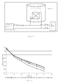
- the SOFC is thus the active unit where the voltage difference (U 0 ) is created and which drives the flow of electrons from the anode (negative electrode) through the external circuit and load (passive unit) to the cathode (positive electrode) which is shown in Fig. 1 .
- the load provides electrical resistance and causes a potential drop.
- the current runs in the opposite direction of the electrons i.e. from the cathode (+) to the anode ( ⁇ ).
- the electrolyte in the SOFC is used to transport oxygen-ions (O 2- ) from the anode chamber to the cathode i.e. opposite of the normal operating mode.
- the electrons are delivered by an external circuit where a Power Supply Unit (PSU) is driving the electrons to the anode of the SOFC.
- PSU Power Supply Unit
- the PSU is thus the active unit in the circuit where the potential difference is created and which drives the electrons from ( ⁇ ) to the anode "through” the stack (by O 2- transport) and from the cathode to (+), which is shown in fig. 2 .
- the SOFC is the passive unit in the circuit, and though the electrons are running in the opposite direction - the anode is still negative and the cathode is positive and the polarity of the SOFC is the same. This is the case because the current is driven by the PSU and not the SOFC.
- the PSU must deliver enough electrons to the anode to keep the individual cell above the reduction potential of Ni to NiO, which is app. 700 mV.
- the reduction potential for Ni re-oxidation is the lower limit for the cell voltage during operation (700 mV) applied in the process of the invention.
- electrons are supplied from the PSU to boost the cell voltages to a value above 700 mV which is the voltage during safe SOFC operation.
- the lower safe limit for the individual cell voltages is 700 mV whereby Ni re-oxidation is avoided, and the upper limit for the voltages is approx. 2000 mV corresponding to the risk of decomposing zirconium when the voltage exceeds 2000 mV.
- Carbon Monoxide is present the upper limit for safe operation is the Carbon monoxide to Carbon reduction potential of app 1500 mV.
- An essential parameter in the inventive process is then to boost the cell voltage to a value between 700 mV and 1500 mV.
- the PSU as shown in Fig. 2 with positive (+) to the cathode and negative ( ⁇ ) to the anode.
- a constant protective voltage should be applied, by connecting the PSU, before stack temperature reaches 300°C. It can be applied at room temperature.
- the voltage from the PSU may be approx. 1000 mV pr cell in the stack, but must be adjusted according to specific cell voltage measurements to keep all cell voltages between 700 and 1500 mV minus production tolerances as shown in Fig. 3 .
- the current is low at 300°C, but increases as the temperature increases. When the fuel cell stack is at operating temperature, then the operational flows can be applied to the stack, and the PSU turned off.
- the PSU can be applied immediately when the SOFC is at open circuit voltage (OCV) and the external load is cut off. This means that no extra control is needed.
- OCV open circuit voltage
- the PSU can be applied when the SOFC is at OCV.
- the fuel flow can then be turned off and the stack will be protected against re-oxidation.
- the SOFC is to be brought back into service, the fuel is supplied and the PSU turned off.
- the PSU is applied when the SOFC is at OCV.
- the fuel flow is then turned off and the SOFC is cooled to room temperature.
- the PSU can be turned off when the SOFC is below 300°C (or at room temperature).
- the anode of the SOFC is protected, which means that no protection gas (from bottle or produced in the system) is needed.
- the process provides quick protection in an easy manner, which ensure that the anode is protected at all times.
- the PSU can be connected to the trip system which monitors the SOFC system during operation and applied if any failure occurs (no fuel, low SOFC voltage, wrong temperatures or pressures, leaks, safety issues or other system components failure). This means that no extra control is needed when using the process of the invention for protection of the SOFC anode.
- the PSU can for instance be a battery, capacitor, AC/DC converter or another fuel cell, and must be able to provide the required voltage in order to maintain sufficient current.
- the process is carried out with a starting temperature corresponding to room temperature, the anode of the SOFC is protected against re-oxidation during the entire start-up. Fuel can be applied at any time after the operational temperature is reached and the PSU can then be turned off.
- the operation temperature is chosen according to the requirements of the fuel cell system design. Conventional operation temperatures of approximately 550 to 850°C are chosen.
- the Fuel Processing System which supplies fuel for the SOFC can be kept cold and inactive until the SOFC is at operating conditions. This means more freedom to operate the fuel processing system during start-up.
- the individual cell voltages can be monitored and even though the cell voltage of a single cell can be above the critical value, a local leakage on the cell will re-oxidize part of the cell, see Fig. 4 .
- the process of the invention is also carried out when the stack is at open circuit voltage (OCV) and it is desired to shut down the system.
- OCV open circuit voltage
- the connection to the power supply unit is maintained.
- Fuel is then cut off and the system is cooled down.
- the SOFC is thus protected at all times with no risk of any re-oxidation of any part of the cells because no part of the cells or stack is close or below the re-oxidation limit of approximately 700 mV.
- the PSU unit is turned off when the SOFC is below 300°C or at room temperature, as no control is needed and measurement of cell voltages is not necessary.
- Fig. 10 is shown an example of a simple natural gas based system during operation.
- Natural Gas and water is fed to a pre-reformer, where the fuel is pre-reformed to a syngas comprising Hydrogen, Methane, Carbon Monoxide and Water. Any higher hydrocarbons present will also be converted to methane.
- the syngas is sent to the anode of the SOFC where it is consumed to produce electricity. Air is simultaneously sent to the cathode to participate in the reactions.
- some of the anode-off gas is recirculated to the pre-reformer to reuse the water produced in the SOFC and to recuperate some of the unused hydrogen.
- the remaining anode off gas not sent to the pre-reformer, is sent to the off gas-burner where it is combusted using excess cathode air.
- pre-reformer and SOFC are protected by sending an inert protection gas through the anode side of the system.
- Both the anode of the SOFC and the pre-reformer are protected by applying the process of the invention.
- the anode of the SOFC is directly protected against re-oxidation by the electric potential applied by the external Power Supply Unit (PSU).
- PSU Power Supply Unit
- the pre-reformer (or any other Fuel Processing Unit) is protected against re-oxidation because the SOFC will produce hydrogen from the residual water present in the recycle loop.
- the residual water from the operation before the trip will immediately be electrolyzed into hydrogen by the solid oxide cell in electrolysis mode and recycled to the FPS.
- the electrolysis in the solid oxide cell can be controlled by keeping the voltage of the PSU constant in the "safe region" between 700 and 1500 mV per cell.
- water can be supplied through the fuel processing system to the solid oxide cell (as during normal operation of a SOFC) and the electrolysis process in the solid oxide cell will keep producing protection gas comprising hydrogen.
- the system of recirculation of hydrogen produced by the SOFC stack can also be used for a Fuel Processing System where hydrogen is needed to process the fuel e.g. a reaction between sulphur and hydrogen to form H 2 S which can be absorbed.
- Other media apart from fuel and water can be added to the fuel processing system e.g. a mixture of steam and air or the separate addition of steam and air respectively.
- a standard stack consisting of 10 SOFC cells was heated to app. 800°C in a pilot plant using electrolysis current as protection against anode nickel re-oxidation.
- the stack was subjected to periods with anode protection using electrolysis current at 800 °C up to 63 hours.
- the stack was characterized with a standard IV-curve to 25 A. The characterizations showed no sign of degradation of any cell in the standard stack, indicating that it is possible to prevent damaging re-oxidation of the anode Ni to NiO using electrolysis current protection, see fig. 6 to Fig. 9 .
- the electrolysis current was aimed to be able to match the average leak current of the stack in order to remove all incoming oxygen to the anode.
- One of the cells (cell 6) had a leak current almost 3 times higher than the average leak current, but there were no signs of degradation of the cell, although it only received about one third of the theoretical needed protection current. Thus it did not appear crucial to have a uniform distribution of the leak current through the stack to be able to protect the stack using electrolysis current.
- the test indicated that an electrolysis current of one third of the cells leak current is enough to protect the anode from re-oxidizing, see Fig. 6 to Fig. 9 .
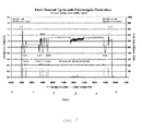
- the stack was subjected to 4 thermal cycles where the stack was heated to app. 800°C, characterized and then cooled to app. 400°C.
- the anode was protected against re-oxidation by electrolysis current during heating up and cooling down. There was no change in ASR or leak current of the stack after 4 thermal cycles with electrolysis current protection of the anode. This indicates that electrolysis current protection is effective during start-up and shut-down, see Fig. 11 and Fig. 12 .
- the stack was heated up without protection gas, but with applied PSU current, then subjected to 4 periods of anode protection using PSU current at operational temperature before shut-down with PSU current as shown in Fig. 7 .
- the stack was characterized between every period with applied PSU current with a standard IV-curve to 25 A. These characterizations where made to compare performance of the stack with the test performed on the standard stack in pilot P5-046 and during the test with the process of the invention in pilot P1-084. The characterization-curves for the tests in pilots P5-046 and P1-084 nos.1-5 are shown in Fig. 6 .
- the stack performance improves from P5-046 to P1-084 UI#1 and again to P1-084 UI#2 which are the two characterizations after start-up with electrolysis current and a period of 1 hour at operational temperature with applied protection current.
- the performance of the stack is then the same for UI Nos. 2 to 5, showing that the anode protection with PSU current is effective during start-up and at operational temperature (800°C) for a period up to approx. 63 hours.
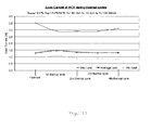
- Fig. 8 shows the calculated minimum, maximum and average ASR at 25 A, standard conditions for the standard stack during the first thermal cycle with periods of anode protection using PSU current. It can be seen that the ASR is reduced from the initial test, and that the ASR is not significantly changed after periods with PSU current to protect the anode from re-oxidation.
- Fig. 9 shows the calculated leak current for the stack from the initial test in pilot P5-046 and during first thermal cycle in pilot P1-084. It can be seen that the average leak is almost constant during the test, indicating that no extra leakage caused by cracking of the anode has a cured.
Landscapes
- Life Sciences & Earth Sciences (AREA)
- Engineering & Computer Science (AREA)
- Manufacturing & Machinery (AREA)
- Sustainable Development (AREA)
- Sustainable Energy (AREA)
- Chemical & Material Sciences (AREA)
- Chemical Kinetics & Catalysis (AREA)
- Electrochemistry (AREA)
- General Chemical & Material Sciences (AREA)
- Fuel Cell (AREA)
- Electrolytic Production Of Non-Metals, Compounds, Apparatuses Therefor (AREA)
Priority Applications (1)
| Application Number | Priority Date | Filing Date | Title |
|---|---|---|---|
| EP14173801.3A EP2811568B1 (fr) | 2010-05-05 | 2010-05-05 | Procédé de fonctionnement pour empilement de piles à combustible à haute température |
Applications Claiming Priority (3)
| Application Number | Priority Date | Filing Date | Title |
|---|---|---|---|
| EP10723498.1A EP2567422B8 (fr) | 2010-05-05 | 2010-05-05 | Processus de fonctionnement pour empilement de piles à combustible à haute température |
| PCT/EP2010/002765 WO2011137916A1 (fr) | 2010-05-05 | 2010-05-05 | Processus de fonctionnement pour empilement de piles à combustible à haute température |
| EP14173801.3A EP2811568B1 (fr) | 2010-05-05 | 2010-05-05 | Procédé de fonctionnement pour empilement de piles à combustible à haute température |
Related Parent Applications (2)
| Application Number | Title | Priority Date | Filing Date |
|---|---|---|---|
| EP10723498.1A Division EP2567422B8 (fr) | 2010-05-05 | 2010-05-05 | Processus de fonctionnement pour empilement de piles à combustible à haute température |
| EP10723498.1A Division-Into EP2567422B8 (fr) | 2010-05-05 | 2010-05-05 | Processus de fonctionnement pour empilement de piles à combustible à haute température |
Publications (2)
| Publication Number | Publication Date |
|---|---|
| EP2811568A1 true EP2811568A1 (fr) | 2014-12-10 |
| EP2811568B1 EP2811568B1 (fr) | 2016-03-23 |
Family
ID=43530499
Family Applications (3)
| Application Number | Title | Priority Date | Filing Date |
|---|---|---|---|
| EP14173801.3A Active EP2811568B1 (fr) | 2010-05-05 | 2010-05-05 | Procédé de fonctionnement pour empilement de piles à combustible à haute température |
| EP10723498.1A Active EP2567422B8 (fr) | 2010-05-05 | 2010-05-05 | Processus de fonctionnement pour empilement de piles à combustible à haute température |
| EP14173799.9A Active EP2811567B1 (fr) | 2010-05-05 | 2010-05-05 | Procédé de fonctionnement pour empilement de piles à combustible à haute température |
Family Applications After (2)
| Application Number | Title | Priority Date | Filing Date |
|---|---|---|---|
| EP10723498.1A Active EP2567422B8 (fr) | 2010-05-05 | 2010-05-05 | Processus de fonctionnement pour empilement de piles à combustible à haute température |
| EP14173799.9A Active EP2811567B1 (fr) | 2010-05-05 | 2010-05-05 | Procédé de fonctionnement pour empilement de piles à combustible à haute température |
Country Status (14)
| Country | Link |
|---|---|
| US (1) | US9005827B2 (fr) |
| EP (3) | EP2811568B1 (fr) |
| JP (1) | JP5738983B2 (fr) |
| KR (1) | KR101753610B1 (fr) |
| CN (1) | CN103026539B (fr) |
| AU (1) | AU2010352713B2 (fr) |
| BR (1) | BR112012028329A2 (fr) |
| CA (1) | CA2798206A1 (fr) |
| DK (1) | DK2567422T3 (fr) |
| EA (1) | EA201291140A8 (fr) |
| ES (1) | ES2508115T3 (fr) |
| TW (1) | TW201218496A (fr) |
| WO (1) | WO2011137916A1 (fr) |
| ZA (1) | ZA201208278B (fr) |
Families Citing this family (32)
| Publication number | Priority date | Publication date | Assignee | Title |
|---|---|---|---|---|
| GB2486001B (en) * | 2010-12-01 | 2012-11-21 | Rolls Royce Fuel Cell Systems Ltd | A solid oxide fuel cell system and a method of operating a solid oxide fuel cell system |
| US20140110270A1 (en) * | 2011-05-26 | 2014-04-24 | Topsøe Fuel Cell A/S | Electrical anode reduction of solid oxide fuel cell |
| CN103855415B (zh) * | 2012-11-29 | 2015-12-02 | 中国科学院大连化学物理研究所 | 一种直接醇类燃料电池经历低温后的性能恢复方法 |
| WO2014108223A1 (fr) | 2013-01-11 | 2014-07-17 | Topsøe Fuel Cell A/S | Procédé de régénération d'empilements de pile à combustible empoisonnée au soufre |
| CN105102684B (zh) * | 2013-01-25 | 2017-09-08 | 托普索公司 | 电解器系统的监测、保护和安全关闭的方法 |
| DE102013214056B4 (de) | 2013-07-17 | 2022-04-07 | Eberspächer Climate Control Systems GmbH & Co. KG | Festoxidbrennstoffzelle |
| JP6163386B2 (ja) * | 2013-08-27 | 2017-07-12 | 三菱日立パワーシステムズ株式会社 | 燃料電池システム、及びその保護方法 |
| JP2015069753A (ja) * | 2013-09-27 | 2015-04-13 | 大阪瓦斯株式会社 | 固体酸化物形燃料電池システム |
| CN106133973A (zh) | 2014-01-31 | 2016-11-16 | 燃料电池能有限公司 | 用于制氢的重整器‑电解槽‑净化器(rep)组件、包含其的系统以及制氢的方法 |
| ES2768174T3 (es) * | 2014-06-27 | 2020-06-22 | Haldor Topsoe As | Fluencia de soporte de ánodo |
| EP3425716A1 (fr) * | 2015-11-16 | 2019-01-09 | Fuelcell Energy, Inc. | Stockage d'énergie au moyen d'un rep (reformeur-électrolyseur-purificateur) pourvu d'un moteur |
| JP6679720B2 (ja) | 2015-11-16 | 2020-04-15 | フュエルセル エナジー, インコーポレイテッドFuelcell Energy, Inc. | 燃料電池からco2を捕捉するシステム |
| KR101992791B1 (ko) | 2015-11-17 | 2019-06-25 | 퓨얼 셀 에너지, 인크 | 부분 산화와 함께 rep를 사용한 수소 및 일산화탄소 생성 |
| WO2017087360A1 (fr) | 2015-11-17 | 2017-05-26 | Fuelcell Energy, Inc. | Système de pile à combustible à capture de co2 améliorée |
| DE102016204609A1 (de) * | 2016-03-21 | 2017-09-21 | Robert Bosch Gmbh | Verfahren zum Betreiben einer Brennstoffzellenvorrichtung |
| US11339333B2 (en) | 2016-04-21 | 2022-05-24 | Fuelcell Energy, Inc. | Fluidized catalytic cracking unit system with integrated reformer-electrolyzer-purifier |
| CN108091907B (zh) | 2016-11-22 | 2020-09-25 | 通用电气公司 | 燃料电池系统及其停机方法 |
| KR101892544B1 (ko) * | 2017-01-20 | 2018-08-28 | 창원대학교 산학협력단 | 고체산화물 연료전지의 음극 산화 방지용 장치 |
| US10897055B2 (en) | 2017-11-16 | 2021-01-19 | Fuelcell Energy, Inc. | Load following power generation and power storage using REP and PEM technology |
| US10483566B2 (en) | 2018-03-20 | 2019-11-19 | Cummins Enterprise Llc | Method and control sub-system for operating a power generation system having a fuel-cell |
| KR102598947B1 (ko) * | 2018-05-04 | 2023-11-06 | 현대자동차주식회사 | 연료전지 시스템 및 그의 제어방법 |
| US11495806B2 (en) | 2019-02-04 | 2022-11-08 | Fuelcell Energy, Inc. | Ultra high efficiency fuel cell power generation system |
| AU2021216120B2 (en) | 2020-02-06 | 2026-01-29 | Topsoe A/S | A method for supplying oxygen-enriched gas to an oxygen-consuming process |
| FR3117684B1 (fr) | 2020-12-11 | 2023-03-31 | Commissariat Energie Atomique | Procédé de fonctionnement en mode stand-by chaud d’une pile à combustible SOFC ou d’un réacteur SOEC. |
| TWI734657B (zh) | 2021-01-15 | 2021-07-21 | 電聯運通股份有限公司 | 燃料電池能源循環利用系統 |
| EP4123056B1 (fr) | 2021-07-20 | 2024-01-17 | Topsoe A/S | Procédé de fonctionnement transitoire d'un empilement de cellule d'électrolyse d'oxyde solide |
| CN115084580B (zh) * | 2022-05-24 | 2024-10-18 | 华北电力大学 | 基于可逆固体氧化物电池可再生能源就地储能系统及方法 |
| KR20240174701A (ko) | 2023-06-09 | 2024-12-17 | 삼성중공업 주식회사 | 2상 유동 배관 구조물 |
| EP4570956A1 (fr) | 2023-12-14 | 2025-06-18 | SolydEra SA | Système électrochimique pour fonctionnement en mode de veille à haute température |
| KR20250094244A (ko) * | 2023-12-18 | 2025-06-25 | 포스코홀딩스 주식회사 | 고온 수전해 시스템의 제어방법 및 제어장치 |
| DE102024206066A1 (de) | 2024-06-28 | 2025-12-31 | Robert Bosch Gesellschaft mit beschränkter Haftung | Verfahren zum Betreiben einer Brennstoffzellenvorrichtung |
| DE102024206933A1 (de) | 2024-07-23 | 2026-01-29 | Robert Bosch Gesellschaft mit beschränkter Haftung | Verfahren zum Betreiben einer Brennstoffzellenvorrichtung |
Citations (9)
| Publication number | Priority date | Publication date | Assignee | Title |
|---|---|---|---|---|
| JPH076778A (ja) | 1992-01-14 | 1995-01-10 | Mitsui Eng & Shipbuild Co Ltd | 高温固体電解質型燃料電池の特性向上方法 |
| US20020028362A1 (en) | 2000-09-01 | 2002-03-07 | Dennis Prediger | Anode oxidation protection in a high-temperature fuel cell |
| US20030235752A1 (en) | 2002-06-24 | 2003-12-25 | England Diane M. | Oxygen getters for anode protection in a solid-oxide fuel cell stack |
| JP2004324060A (ja) | 2003-04-21 | 2004-11-18 | Sekisui Chem Co Ltd | マンホールの更生工法 |
| US20050095469A1 (en) | 2002-03-02 | 2005-05-05 | Marc Bednarz | Method for inerting the anodes of fuel cells |
| WO2005101556A1 (fr) | 2004-04-15 | 2005-10-27 | Versa Power Systems, Ltd. | Arret d'une pile a combustible avec purge de vapeur |
| US20060141300A1 (en) | 2004-12-27 | 2006-06-29 | Versa Power Systems, Ltd. | Preconditioning treatment to enhance redox tolerance of solid oxide fuel cells |
| WO2007068510A1 (fr) * | 2005-12-12 | 2007-06-21 | Forschungszentrum Jülich GmbH | Pile à combustible à haute température stable à la réoxydation |
| EP2112708A2 (fr) * | 2008-04-04 | 2009-10-28 | Delphi Technologies, Inc. | Procédé et appareil pour la prévention d'oxydation d'anode et refroidissement d'un bloc de piles à combustible à oxyde solide |
Family Cites Families (8)
| Publication number | Priority date | Publication date | Assignee | Title |
|---|---|---|---|---|
| US7432002B2 (en) * | 2002-09-30 | 2008-10-07 | E.I. Du Pont De Nemours And Company | Method for regeneration of performance in a fuel cell |
| US20040126632A1 (en) * | 2002-12-27 | 2004-07-01 | Pearson Martin T. | Regenerative fuel cell electric power plant and operating method |
| US7575822B2 (en) * | 2003-04-09 | 2009-08-18 | Bloom Energy Corporation | Method of optimizing operating efficiency of fuel cells |
| US20060194082A1 (en) * | 2005-02-02 | 2006-08-31 | Ultracell Corporation | Systems and methods for protecting a fuel cell |
| US7700210B2 (en) * | 2005-05-10 | 2010-04-20 | Bloom Energy Corporation | Increasing thermal dissipation of fuel cell stacks under partial electrical load |
| EP1986264A1 (fr) * | 2007-04-26 | 2008-10-29 | Technische Universität München | Système pour la génération d'énergie électrique comprenant un reformeur électrochimique et une pile à combustible |
| JP5081542B2 (ja) | 2007-09-03 | 2012-11-28 | 本田技研工業株式会社 | 燃料電池システム及びその運転方法 |
| JP5001761B2 (ja) * | 2007-09-10 | 2012-08-15 | Jx日鉱日石エネルギー株式会社 | 水蒸気発生器及び燃料電池システムの運転方法 |
-
2010
- 2010-05-05 AU AU2010352713A patent/AU2010352713B2/en not_active Ceased
- 2010-05-05 KR KR1020127031744A patent/KR101753610B1/ko active Active
- 2010-05-05 JP JP2013508374A patent/JP5738983B2/ja active Active
- 2010-05-05 US US13/695,944 patent/US9005827B2/en active Active
- 2010-05-05 ES ES10723498.1T patent/ES2508115T3/es active Active
- 2010-05-05 WO PCT/EP2010/002765 patent/WO2011137916A1/fr not_active Ceased
- 2010-05-05 EA EA201291140A patent/EA201291140A8/ru unknown
- 2010-05-05 CA CA2798206A patent/CA2798206A1/fr not_active Abandoned
- 2010-05-05 DK DK10723498.1T patent/DK2567422T3/da active
- 2010-05-05 EP EP14173801.3A patent/EP2811568B1/fr active Active
- 2010-05-05 BR BR112012028329A patent/BR112012028329A2/pt not_active IP Right Cessation
- 2010-05-05 EP EP10723498.1A patent/EP2567422B8/fr active Active
- 2010-05-05 CN CN201080066611.6A patent/CN103026539B/zh active Active
- 2010-05-05 EP EP14173799.9A patent/EP2811567B1/fr active Active
-
2011
- 2011-05-03 TW TW100115441A patent/TW201218496A/zh unknown
-
2012
- 2012-11-05 ZA ZA2012/08278A patent/ZA201208278B/en unknown
Patent Citations (9)
| Publication number | Priority date | Publication date | Assignee | Title |
|---|---|---|---|---|
| JPH076778A (ja) | 1992-01-14 | 1995-01-10 | Mitsui Eng & Shipbuild Co Ltd | 高温固体電解質型燃料電池の特性向上方法 |
| US20020028362A1 (en) | 2000-09-01 | 2002-03-07 | Dennis Prediger | Anode oxidation protection in a high-temperature fuel cell |
| US20050095469A1 (en) | 2002-03-02 | 2005-05-05 | Marc Bednarz | Method for inerting the anodes of fuel cells |
| US20030235752A1 (en) | 2002-06-24 | 2003-12-25 | England Diane M. | Oxygen getters for anode protection in a solid-oxide fuel cell stack |
| JP2004324060A (ja) | 2003-04-21 | 2004-11-18 | Sekisui Chem Co Ltd | マンホールの更生工法 |
| WO2005101556A1 (fr) | 2004-04-15 | 2005-10-27 | Versa Power Systems, Ltd. | Arret d'une pile a combustible avec purge de vapeur |
| US20060141300A1 (en) | 2004-12-27 | 2006-06-29 | Versa Power Systems, Ltd. | Preconditioning treatment to enhance redox tolerance of solid oxide fuel cells |
| WO2007068510A1 (fr) * | 2005-12-12 | 2007-06-21 | Forschungszentrum Jülich GmbH | Pile à combustible à haute température stable à la réoxydation |
| EP2112708A2 (fr) * | 2008-04-04 | 2009-10-28 | Delphi Technologies, Inc. | Procédé et appareil pour la prévention d'oxydation d'anode et refroidissement d'un bloc de piles à combustible à oxyde solide |
Also Published As
| Publication number | Publication date |
|---|---|
| KR101753610B1 (ko) | 2017-07-04 |
| JP5738983B2 (ja) | 2015-06-24 |
| WO2011137916A1 (fr) | 2011-11-10 |
| US9005827B2 (en) | 2015-04-14 |
| EP2567422B1 (fr) | 2014-07-16 |
| JP2013530490A (ja) | 2013-07-25 |
| AU2010352713B2 (en) | 2014-07-31 |
| EA201291140A8 (ru) | 2014-02-28 |
| KR20130071435A (ko) | 2013-06-28 |
| ZA201208278B (en) | 2014-01-29 |
| EP2811567B1 (fr) | 2016-03-23 |
| EP2811567A1 (fr) | 2014-12-10 |
| TW201218496A (en) | 2012-05-01 |
| CA2798206A1 (fr) | 2011-11-10 |
| ES2508115T3 (es) | 2014-10-16 |
| US20130052548A1 (en) | 2013-02-28 |
| EP2567422B8 (fr) | 2015-03-11 |
| EP2567422A1 (fr) | 2013-03-13 |
| EP2811568B1 (fr) | 2016-03-23 |
| BR112012028329A2 (pt) | 2017-03-21 |
| CN103026539A (zh) | 2013-04-03 |
| EA201291140A1 (ru) | 2013-05-30 |
| CN103026539B (zh) | 2015-08-26 |
| DK2567422T3 (da) | 2014-10-27 |
Similar Documents
| Publication | Publication Date | Title |
|---|---|---|
| EP2811568B1 (fr) | Procédé de fonctionnement pour empilement de piles à combustible à haute température | |
| AU2010352713A1 (en) | Process for operating a high temperature fuel cell stack | |
| US20020028362A1 (en) | Anode oxidation protection in a high-temperature fuel cell | |
| US6696190B2 (en) | Fuel cell system and method | |
| JP4961682B2 (ja) | 燃料電池発電装置および運転停止方法 | |
| EP2375484B1 (fr) | Procédé de fonctionnement d'un système de pile à combustible | |
| JP2004172105A (ja) | 燃料電池システムの運転方法および燃料電池システム | |
| EP3259795B1 (fr) | Oxydation électrochimique de dépôts carbonés dans des piles à combustible à oxyde solide alimentées aux hydrocarbures liquides | |
| JP2004172106A (ja) | 燃料電池システムの運転方法および燃料電池システム | |
| JP2009245693A (ja) | 燃料電池発電装置及び停止時の制御方法並びに制御プログラム | |
| KR101892544B1 (ko) | 고체산화물 연료전지의 음극 산화 방지용 장치 | |
| US12009558B2 (en) | Fuel cell system and method for controlling fuel cell system | |
| KR101435394B1 (ko) | 연료전지 운영 시스템 및 그 방법 | |
| JP2009245692A (ja) | 燃料電池発電装置及び酸化剤ガスの流路異常検出方法並びに流路異常検出プログラム | |
| JP2006134767A (ja) | 固体酸化物形燃料電池システム | |
| KR20190026020A (ko) | 연료 전지 전극의 재생 | |
| JP2008135204A (ja) | 燃料電池発電装置及びその制御方法並びに制御プログラム | |
| KR20070093279A (ko) | 성능회복장치를 장착한 연료전지 시스템 | |
| JP2007335354A (ja) | 燃料電池発電装置及び燃料電池スタックの劣化状態診断方法 |
Legal Events
| Date | Code | Title | Description |
|---|---|---|---|
| PUAI | Public reference made under article 153(3) epc to a published international application that has entered the european phase |
Free format text: ORIGINAL CODE: 0009012 |
|
| 17P | Request for examination filed |
Effective date: 20140625 |
|
| AC | Divisional application: reference to earlier application |
Ref document number: 2567422 Country of ref document: EP Kind code of ref document: P |
|
| AK | Designated contracting states |
Kind code of ref document: A1 Designated state(s): AL AT BE BG CH CY CZ DE DK EE ES FI FR GB GR HR HU IE IS IT LI LT LU LV MC MK MT NL NO PL PT RO SE SI SK SM TR |
|
| RAP1 | Party data changed (applicant data changed or rights of an application transferred) |
Owner name: TECHNICAL UNIVERSITY OF DENMARK Owner name: HALDOR TOPSOEE A/S |
|
| R17P | Request for examination filed (corrected) |
Effective date: 20150410 |
|
| RBV | Designated contracting states (corrected) |
Designated state(s): AL AT BE BG CH CY CZ DE DK EE ES FI FR GB GR HR HU IE IS IT LI LT LU LV MC MK MT NL NO PL PT RO SE SI SK SM TR |
|
| RIC1 | Information provided on ipc code assigned before grant |
Ipc: H01M 8/06 20060101ALN20150820BHEP Ipc: H01M 8/12 20060101ALN20150820BHEP Ipc: H01M 8/04 20060101AFI20150820BHEP Ipc: H01M 8/14 20060101ALN20150820BHEP |
|
| RAP1 | Party data changed (applicant data changed or rights of an application transferred) |
Owner name: HALDOR TOPSOEE A/S Owner name: TECHNICAL UNIVERSITY OF DENMARK |
|
| GRAP | Despatch of communication of intention to grant a patent |
Free format text: ORIGINAL CODE: EPIDOSNIGR1 |
|
| INTG | Intention to grant announced |
Effective date: 20151016 |
|
| GRAS | Grant fee paid |
Free format text: ORIGINAL CODE: EPIDOSNIGR3 |
|
| GRAA | (expected) grant |
Free format text: ORIGINAL CODE: 0009210 |
|
| AC | Divisional application: reference to earlier application |
Ref document number: 2567422 Country of ref document: EP Kind code of ref document: P |
|
| AK | Designated contracting states |
Kind code of ref document: B1 Designated state(s): AL AT BE BG CH CY CZ DE DK EE ES FI FR GB GR HR HU IE IS IT LI LT LU LV MC MK MT NL NO PL PT RO SE SI SK SM TR |
|
| REG | Reference to a national code |
Ref country code: GB Ref legal event code: FG4D |
|
| REG | Reference to a national code |
Ref country code: CH Ref legal event code: EP |
|
| REG | Reference to a national code |
Ref country code: AT Ref legal event code: REF Ref document number: 783942 Country of ref document: AT Kind code of ref document: T Effective date: 20160415 |
|
| REG | Reference to a national code |
Ref country code: IE Ref legal event code: FG4D |
|
| REG | Reference to a national code |
Ref country code: DE Ref legal event code: R096 Ref document number: 602010031534 Country of ref document: DE |
|
| REG | Reference to a national code |
Ref country code: LT Ref legal event code: MG4D |
|
| REG | Reference to a national code |
Ref country code: NL Ref legal event code: MP Effective date: 20160323 |
|
| PG25 | Lapsed in a contracting state [announced via postgrant information from national office to epo] |
Ref country code: NO Free format text: LAPSE BECAUSE OF FAILURE TO SUBMIT A TRANSLATION OF THE DESCRIPTION OR TO PAY THE FEE WITHIN THE PRESCRIBED TIME-LIMIT Effective date: 20160623 Ref country code: GR Free format text: LAPSE BECAUSE OF FAILURE TO SUBMIT A TRANSLATION OF THE DESCRIPTION OR TO PAY THE FEE WITHIN THE PRESCRIBED TIME-LIMIT Effective date: 20160624 Ref country code: FI Free format text: LAPSE BECAUSE OF FAILURE TO SUBMIT A TRANSLATION OF THE DESCRIPTION OR TO PAY THE FEE WITHIN THE PRESCRIBED TIME-LIMIT Effective date: 20160323 Ref country code: HR Free format text: LAPSE BECAUSE OF FAILURE TO SUBMIT A TRANSLATION OF THE DESCRIPTION OR TO PAY THE FEE WITHIN THE PRESCRIBED TIME-LIMIT Effective date: 20160323 |
|
| REG | Reference to a national code |
Ref country code: AT Ref legal event code: MK05 Ref document number: 783942 Country of ref document: AT Kind code of ref document: T Effective date: 20160323 |
|
| PG25 | Lapsed in a contracting state [announced via postgrant information from national office to epo] |
Ref country code: SE Free format text: LAPSE BECAUSE OF FAILURE TO SUBMIT A TRANSLATION OF THE DESCRIPTION OR TO PAY THE FEE WITHIN THE PRESCRIBED TIME-LIMIT Effective date: 20160323 Ref country code: LT Free format text: LAPSE BECAUSE OF FAILURE TO SUBMIT A TRANSLATION OF THE DESCRIPTION OR TO PAY THE FEE WITHIN THE PRESCRIBED TIME-LIMIT Effective date: 20160323 Ref country code: BE Free format text: LAPSE BECAUSE OF NON-PAYMENT OF DUE FEES Effective date: 20160531 Ref country code: NL Free format text: LAPSE BECAUSE OF FAILURE TO SUBMIT A TRANSLATION OF THE DESCRIPTION OR TO PAY THE FEE WITHIN THE PRESCRIBED TIME-LIMIT Effective date: 20160323 Ref country code: LV Free format text: LAPSE BECAUSE OF FAILURE TO SUBMIT A TRANSLATION OF THE DESCRIPTION OR TO PAY THE FEE WITHIN THE PRESCRIBED TIME-LIMIT Effective date: 20160323 |
|
| PG25 | Lapsed in a contracting state [announced via postgrant information from national office to epo] |
Ref country code: PL Free format text: LAPSE BECAUSE OF FAILURE TO SUBMIT A TRANSLATION OF THE DESCRIPTION OR TO PAY THE FEE WITHIN THE PRESCRIBED TIME-LIMIT Effective date: 20160323 Ref country code: EE Free format text: LAPSE BECAUSE OF FAILURE TO SUBMIT A TRANSLATION OF THE DESCRIPTION OR TO PAY THE FEE WITHIN THE PRESCRIBED TIME-LIMIT Effective date: 20160323 Ref country code: IS Free format text: LAPSE BECAUSE OF FAILURE TO SUBMIT A TRANSLATION OF THE DESCRIPTION OR TO PAY THE FEE WITHIN THE PRESCRIBED TIME-LIMIT Effective date: 20160723 |
|
| PG25 | Lapsed in a contracting state [announced via postgrant information from national office to epo] |
Ref country code: ES Free format text: LAPSE BECAUSE OF FAILURE TO SUBMIT A TRANSLATION OF THE DESCRIPTION OR TO PAY THE FEE WITHIN THE PRESCRIBED TIME-LIMIT Effective date: 20160323 Ref country code: CZ Free format text: LAPSE BECAUSE OF FAILURE TO SUBMIT A TRANSLATION OF THE DESCRIPTION OR TO PAY THE FEE WITHIN THE PRESCRIBED TIME-LIMIT Effective date: 20160323 Ref country code: PT Free format text: LAPSE BECAUSE OF FAILURE TO SUBMIT A TRANSLATION OF THE DESCRIPTION OR TO PAY THE FEE WITHIN THE PRESCRIBED TIME-LIMIT Effective date: 20160725 Ref country code: AT Free format text: LAPSE BECAUSE OF FAILURE TO SUBMIT A TRANSLATION OF THE DESCRIPTION OR TO PAY THE FEE WITHIN THE PRESCRIBED TIME-LIMIT Effective date: 20160323 Ref country code: SK Free format text: LAPSE BECAUSE OF FAILURE TO SUBMIT A TRANSLATION OF THE DESCRIPTION OR TO PAY THE FEE WITHIN THE PRESCRIBED TIME-LIMIT Effective date: 20160323 Ref country code: SM Free format text: LAPSE BECAUSE OF FAILURE TO SUBMIT A TRANSLATION OF THE DESCRIPTION OR TO PAY THE FEE WITHIN THE PRESCRIBED TIME-LIMIT Effective date: 20160323 Ref country code: RO Free format text: LAPSE BECAUSE OF FAILURE TO SUBMIT A TRANSLATION OF THE DESCRIPTION OR TO PAY THE FEE WITHIN THE PRESCRIBED TIME-LIMIT Effective date: 20160323 |
|
| PG25 | Lapsed in a contracting state [announced via postgrant information from national office to epo] |
Ref country code: LU Free format text: LAPSE BECAUSE OF FAILURE TO SUBMIT A TRANSLATION OF THE DESCRIPTION OR TO PAY THE FEE WITHIN THE PRESCRIBED TIME-LIMIT Effective date: 20160505 Ref country code: IT Free format text: LAPSE BECAUSE OF FAILURE TO SUBMIT A TRANSLATION OF THE DESCRIPTION OR TO PAY THE FEE WITHIN THE PRESCRIBED TIME-LIMIT Effective date: 20160323 Ref country code: BE Free format text: LAPSE BECAUSE OF FAILURE TO SUBMIT A TRANSLATION OF THE DESCRIPTION OR TO PAY THE FEE WITHIN THE PRESCRIBED TIME-LIMIT Effective date: 20160323 |
|
| REG | Reference to a national code |
Ref country code: CH Ref legal event code: PL |
|
| REG | Reference to a national code |
Ref country code: DE Ref legal event code: R097 Ref document number: 602010031534 Country of ref document: DE |
|
| PLBE | No opposition filed within time limit |
Free format text: ORIGINAL CODE: 0009261 |
|
| STAA | Information on the status of an ep patent application or granted ep patent |
Free format text: STATUS: NO OPPOSITION FILED WITHIN TIME LIMIT |
|
| PG25 | Lapsed in a contracting state [announced via postgrant information from national office to epo] |
Ref country code: LI Free format text: LAPSE BECAUSE OF NON-PAYMENT OF DUE FEES Effective date: 20160531 Ref country code: DK Free format text: LAPSE BECAUSE OF FAILURE TO SUBMIT A TRANSLATION OF THE DESCRIPTION OR TO PAY THE FEE WITHIN THE PRESCRIBED TIME-LIMIT Effective date: 20160323 Ref country code: CH Free format text: LAPSE BECAUSE OF NON-PAYMENT OF DUE FEES Effective date: 20160531 |
|
| REG | Reference to a national code |
Ref country code: IE Ref legal event code: MM4A |
|
| PG25 | Lapsed in a contracting state [announced via postgrant information from national office to epo] |
Ref country code: BG Free format text: LAPSE BECAUSE OF FAILURE TO SUBMIT A TRANSLATION OF THE DESCRIPTION OR TO PAY THE FEE WITHIN THE PRESCRIBED TIME-LIMIT Effective date: 20160623 |
|
| 26N | No opposition filed |
Effective date: 20170102 |
|
| REG | Reference to a national code |
Ref country code: FR Ref legal event code: ST Effective date: 20170131 |
|
| PG25 | Lapsed in a contracting state [announced via postgrant information from national office to epo] |
Ref country code: FR Free format text: LAPSE BECAUSE OF NON-PAYMENT OF DUE FEES Effective date: 20160531 |
|
| PG25 | Lapsed in a contracting state [announced via postgrant information from national office to epo] |
Ref country code: IE Free format text: LAPSE BECAUSE OF NON-PAYMENT OF DUE FEES Effective date: 20160505 Ref country code: SI Free format text: LAPSE BECAUSE OF FAILURE TO SUBMIT A TRANSLATION OF THE DESCRIPTION OR TO PAY THE FEE WITHIN THE PRESCRIBED TIME-LIMIT Effective date: 20160323 |
|
| PG25 | Lapsed in a contracting state [announced via postgrant information from national office to epo] |
Ref country code: HU Free format text: LAPSE BECAUSE OF FAILURE TO SUBMIT A TRANSLATION OF THE DESCRIPTION OR TO PAY THE FEE WITHIN THE PRESCRIBED TIME-LIMIT; INVALID AB INITIO Effective date: 20100505 |
|
| PG25 | Lapsed in a contracting state [announced via postgrant information from national office to epo] |
Ref country code: MC Free format text: LAPSE BECAUSE OF FAILURE TO SUBMIT A TRANSLATION OF THE DESCRIPTION OR TO PAY THE FEE WITHIN THE PRESCRIBED TIME-LIMIT Effective date: 20160323 Ref country code: MK Free format text: LAPSE BECAUSE OF FAILURE TO SUBMIT A TRANSLATION OF THE DESCRIPTION OR TO PAY THE FEE WITHIN THE PRESCRIBED TIME-LIMIT Effective date: 20160323 Ref country code: MT Free format text: LAPSE BECAUSE OF NON-PAYMENT OF DUE FEES Effective date: 20160531 Ref country code: CY Free format text: LAPSE BECAUSE OF FAILURE TO SUBMIT A TRANSLATION OF THE DESCRIPTION OR TO PAY THE FEE WITHIN THE PRESCRIBED TIME-LIMIT Effective date: 20160323 |
|
| PG25 | Lapsed in a contracting state [announced via postgrant information from national office to epo] |
Ref country code: TR Free format text: LAPSE BECAUSE OF FAILURE TO SUBMIT A TRANSLATION OF THE DESCRIPTION OR TO PAY THE FEE WITHIN THE PRESCRIBED TIME-LIMIT Effective date: 20160323 Ref country code: AL Free format text: LAPSE BECAUSE OF FAILURE TO SUBMIT A TRANSLATION OF THE DESCRIPTION OR TO PAY THE FEE WITHIN THE PRESCRIBED TIME-LIMIT Effective date: 20160323 |
|
| P01 | Opt-out of the competence of the unified patent court (upc) registered |
Effective date: 20230602 |
|
| REG | Reference to a national code |
Ref country code: DE Ref legal event code: R081 Ref document number: 602010031534 Country of ref document: DE Owner name: TOPSOE A/S, DK Free format text: FORMER OWNERS: THE TECHNICAL UNIVERSITY OF DENMARK, LYNGBY, DK; TOPSOE A/S, LYNGBY, DK Ref country code: DE Ref legal event code: R081 Ref document number: 602010031534 Country of ref document: DE Owner name: TOPSOE A/S, DK Free format text: FORMER OWNERS: HALDOR TOPSOE A/S, KGS. LYNGBY, DK; TECHNICAL UNIVERSITY OF DENMARK, KGS. LYNGBY, DK |
|
| REG | Reference to a national code |
Ref country code: GB Ref legal event code: 732E Free format text: REGISTERED BETWEEN 20240822 AND 20240828 |
|
| P02 | Opt-out of the competence of the unified patent court (upc) changed |
Free format text: CASE NUMBER: APP_49081/2024 Effective date: 20240828 |
|
| PGFP | Annual fee paid to national office [announced via postgrant information from national office to epo] |
Ref country code: DE Payment date: 20250528 Year of fee payment: 16 |
|
| PGFP | Annual fee paid to national office [announced via postgrant information from national office to epo] |
Ref country code: GB Payment date: 20250520 Year of fee payment: 16 |