EP2811574A1 - Starres Radom für eine Antenne mit Konkavreflektor - Google Patents
Starres Radom für eine Antenne mit Konkavreflektor Download PDFInfo
- Publication number
- EP2811574A1 EP2811574A1 EP13305736.4A EP13305736A EP2811574A1 EP 2811574 A1 EP2811574 A1 EP 2811574A1 EP 13305736 A EP13305736 A EP 13305736A EP 2811574 A1 EP2811574 A1 EP 2811574A1
- Authority
- EP
- European Patent Office
- Prior art keywords
- layer
- radome
- area
- antenna
- layers
- Prior art date
- Legal status (The legal status is an assumption and is not a legal conclusion. Google has not performed a legal analysis and makes no representation as to the accuracy of the status listed.)
- Granted
Links
Images


Classifications
-
- H—ELECTRICITY
- H01—ELECTRIC ELEMENTS
- H01Q—ANTENNAS, i.e. RADIO AERIALS
- H01Q1/00—Details of, or arrangements associated with, antennas
- H01Q1/42—Housings not intimately mechanically associated with radiating elements, e.g. radome
-
- H—ELECTRICITY
- H01—ELECTRIC ELEMENTS
- H01Q—ANTENNAS, i.e. RADIO AERIALS
- H01Q1/00—Details of, or arrangements associated with, antennas
- H01Q1/42—Housings not intimately mechanically associated with radiating elements, e.g. radome
- H01Q1/421—Means for correcting aberrations introduced by a radome
-
- H—ELECTRICITY
- H01—ELECTRIC ELEMENTS
- H01Q—ANTENNAS, i.e. RADIO AERIALS
- H01Q1/00—Details of, or arrangements associated with, antennas
- H01Q1/42—Housings not intimately mechanically associated with radiating elements, e.g. radome
- H01Q1/422—Housings not intimately mechanically associated with radiating elements, e.g. radome comprising two or more layers of dielectric material
-
- H—ELECTRICITY
- H01—ELECTRIC ELEMENTS
- H01Q—ANTENNAS, i.e. RADIO AERIALS
- H01Q1/00—Details of, or arrangements associated with, antennas
- H01Q1/42—Housings not intimately mechanically associated with radiating elements, e.g. radome
- H01Q1/422—Housings not intimately mechanically associated with radiating elements, e.g. radome comprising two or more layers of dielectric material
- H01Q1/424—Housings not intimately mechanically associated with radiating elements, e.g. radome comprising two or more layers of dielectric material comprising a layer of expanded material
Definitions
- the present invention relates to a telecommunication antenna with concave reflector having for example the shape of at least one parabola portion.
- These antennas in particular of the microwave type, are usually used in mobile communication networks. These antennas operate indifferently in transmitter mode or in receiver mode, corresponding to two opposite directions of RF wave propagation.
- the reflector is associated with a radome having an impervious protective surface which partitions the space defined by the reflector, with or without a skirt, vis-à-vis the outside.
- This radome can be flexible or rigid.
- a rigid radome, the most currently used, has the advantage of good resistance to the external climate environment such as rain, wind or snow.
- the thickness of the material used in a rigid radome is problematic since this thickness is determined as a function of the frequency band used by the antenna.
- the thickness of a rigid radome implemented in an antenna transmitting with a frequency of 40 GHz is practically half of the thickness of a rigid radome of the same kind used in an antenna transmitting with a frequency of 20 GHz. It is understood that to use the antenna over a wide frequency band, ranging from 5 to 25 GHz, for example, it is necessary to use five radomes of different thickness. These radomes must be dismantled and replaced at each frequency domain change.
- radomes having a sandwich structure consisting of a cellular core structure with a thickness of about 3 mm and two external plates having a thickness of order of 0.35 mm each.
- Such a structure has excellent radio performance for frequencies around 25 GHz, but has more modest performance for frequencies far from this target.
- This phenomenon is due to the difference between the actual thickness of the radome and the reference thickness which is adapted to the value of a half-wavelength at the center frequency of the bandwidth.
- Such a radome having a thickness equal to the reference thickness is called a "half-wave radome".
- the reflection coefficients of the radome can exceed -20 dB, which affects the performance of the antenna .
- the present invention aims to eliminate the disadvantages of the prior art, by providing a rigid radome for operation with satisfactory performance of a parabolic antenna in a wider frequency range than the prior art, without which it is necessary to change it.
- the present invention therefore aims to improve the performance of the antennas for frequencies below the target frequencies of the radome and the antenna, without the need to change it.
- the object of the present invention is a radome intended to be mounted on an antenna, said radome comprising a first layer and at least a second layer attached to said first layer so as to increase the effective thickness of said radome on at least a portion of its surface, the area of said second layer being strictly less than 100% of the area of said first layer.
- the first layer may be made of a rigid or flexible material, and adopt a flat, curved or conical shape.
- a half-wave radome is usually preferred, which is very thick and therefore expensive material.
- the present invention makes it possible to adapt a radome with a sandwich-type structure to use at low frequencies while avoiding the use of a radome with a very thick "sandwich” type structure or a radome with a conical shape. or spherical, which is very difficult to achieve with multilayer materials.
- the second layer of the radome is formed of a material of the same nature as the first layer.
- the second layer of the radome is attached to the first layer via a spacer so as to space said second layer of said first layer at least over a portion thereof.
- a radome has spacers allowing a spacing of the first and second layers between 10 mm and 3 mm.
- the surface of the second layer of the radome may have a shape different from the surface of the first layer.
- the surface of the second layer of the radome is curved and the surface of the first layer of the radome is flat.
- the surface of the second layer of the radome is flat and the surface of the first layer of the radome is curved.
- the second layer may be made of a rigid or flexible material, and adopt a flat or curved shape.
- the second layer of the radome may have a polygonal surface, such as for example a triangle or a hexagon or a quadrilateral such as a rectangle or a square, or a shaped surface defined by a closed curve such as a circle, an oval or an oblong.
- the area of the second layer covers at least 70% of the area of said first layer, and preferably at least 50% of the area of said first layer.
- the second layer is removably attached to the first layer.
- the space between the first and second layers can be filled with low density foam.
- a second object according to the present invention is an antenna having a radome according to any one of the above aspects.
- the second layer of the radome is arranged so as to face a reflector of said antenna.
- the second layer is disposed on the inner face of the radome facing the waveguide.
- a third object according to the invention is a method of manufacturing a radome, comprising the following steps: providing a first layer of a radome and fixing a second layer on the surface of said radome so as to increase the effective thickness of said radome the area of said second layer being strictly less than 100% of the area of said first layer.
- the second layer is secured to the first layer of the radome with spacers so as to space said second layer of said first layer of said radome on at least a portion of said second layer.
- an antenna 10 provided with its fixing means 12, for example to be fixed on Matt.
- the antenna 10 comprises a parabolic reflector 14 at the center of which is placed a waveguide (not shown).
- a radome 20 fixed at its periphery on the reflector 14 covers the dish 14.
- the attachment points of the radome 20 to the dish 14 are illustrated with the reference 22.
- the first layer may be made of a rigid or flexible material which allows, as the case may be, to obtain a flat, curved or conical shape.
- Various materials can be used for the construction of the radome such as a polymer (ABS, PS, PVC, PP) injected or thermoformed. They have in common to attenuate to a minimum the signal sent and received.
- the radome 20 may for example consist of a sandwich-type multilayer material comprising two dense outer plates surrounding at least one central portion containing a high proportion of air.
- the outer plates, which are continuous flat thin plates, and the three-dimensional central portion are made of the same polymeric material, preferably polypropylene (PP).
- the radome 20 may especially be of the "honeycomb” type whose cells have a substantially conical shape or of the "honeycomb” type.
- first layer 24 For the purposes of the following description, whatever the structure of the first monolayer or multilayer layer 24 of the radome 20, it will be named in the singular "layer”.
- the composition of the first layer 24 is well known to those skilled in the art and will not be further detailed.
- a second layer 30 (visible in transparency) is fixed to said first layer 24.
- the second layer 30 is arranged so as to be in front of the guide of FIG. wave of the antenna 10, that is to say on the inner surface of the radome 20 when it is mounted on the reflector 14.
- the goal is to make the radome transparent to the waves.
- a wave meets a radome, there is of course a transmitted wave but also a partially reflected wave.
- this reflected wave can be canceled over a defined bandwidth. Indeed the waves reflected on the different layers are superimposed and can cancel if the sum of the phases is zero.
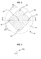
- FIG. 2 illustrates in more detail the internal face of the radome 20 comprising the first layer 24.
- a second layer 30 is fixed to the first layer 24.
- the second layer 30 is preferably made of materials of the same nature as for the layer 24. However, since it does not directly undergo the external influences, that is to say the wind and the UV radiation, its mechanical characteristics can be eased.
- the area of the second layer 30 should be strictly less than 100% of the area of the first layer 24, and preferably the area of the second layer 30 should have at least 50%, and preferably at least 70%, of the the area of the first layer 24 to have a significant radioelectric impact.
- the second layer 30 may furthermore have any shape, and preferably polygonal shapes such as a hexagon, triangle or quadrilateral such as a parallelogram, a square, a rectangle, a rhombus, a trapezium, etc., although circular or oblong shapes are allowed.
- a square shape is from the point of view simplicity preferable because easier and less expensive to produce.
- any other form is possible if the minimum ratio of areas is greater than about 50%.
- the second layer 30 may be fixed to the first layer 24 in any manner and using all the means available for this purpose according to the constraints known to those skilled in the art.
- the second layer 30 may in particular be attached to attachment points 32 as illustrated, or plated continuously over the entire surface of the first layer.
- the attachment points 32 can fix the second layer 30 in contact with the first layer 24, just as these attachment points 32 can also keep the second layer 30 spaced from said first layer 24.
- the spacing between the first and second layers may vary and not remain constant.
- the attachment points 32 are preferably made of UV-resistant plastic materials, and of a structure sufficiently strong to hold the two layers in place.
- the fixing points have a small diameter so that the set of attachment points 32 represents an area less than 0.05% of the surface of the radome.
- these attachment points 32 between the second layer 30 and the first layer 24 of the radome 20 may in particular be fastening clips, allowing easy attachment of the second layer 32 to the radome 20. These clips 32 can thus allow easy and quick disassembly of the second layer 32.
- FIGS. 4 to 6 illustrate possible alternative arrangements of the first and second layers 24, 30, i.e., a radome according to various embodiments.
- the figure 4 illustrates a variant in which the second layer 30 is fixed to the main layer 24 of the radome by attachment points 32 on the periphery of said second layer 30, as well as by one or more central attachment point (s) 32.
- spacers 44 of equal thickness are mounted co-axially with the attachment points 32 to maintain a constant spacing between said first and second layers.
- the spacers 34 preferably have a height of between 10 mm and 3 mm.
- the figure 5 illustrates a variant in which the second layer 30 is fixed to the first layer 24 of the radome by attachment points 32 on the periphery of said second layer 30, as well as by one or more central attachment point (s) 32.
- one or more struts 54 are mounted co-axially with the attachment points 32 only on the central portion of the first and second layers 24, 30 to have a curved shape, and more particularly to give a convex surface to the second layer 30 with respect to the flat surface of the first layer 24.
- the struts 54 of the central portion preferably have a height of between 10 mm and 3 mm.
- the figure 6 illustrates a variant in which the second layer 30 is fixed to the first layer 24 of the radome by attachment points 32 on the periphery of said second layer 30, as well as by one or more central attachment point (s) 32.
- one or more struts 64 are mounted co-axially with the attachment points 32 only on the peripheral portion of the first and second layers 24, 30 to give the second layer 30 a curved shape, and more particularly so that it has a concave surface with respect to the planar surface of the first layer 24.
- the spacers 34 preferably have a length of between 10 mm and 3 mm. It should be noted that the material of the second layer 30 must have some resilience to bending to allow a curved shape.
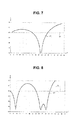
- Figures 7 and 8 illustrate the value of the reflection coefficient R in dB, or standing wave ratio, as a function of the frequency F in GHz of the wave incident on the radome over a frequency range from 6 to 40 GHz, for this radome ( figure 8 ) and a known radome ( figure 7 ).
- the known radome adapted for operation in the frequency range 20-30 GHz, corresponding to the performances of the figure 7 (curve 107) has a single layer of thickness 3.7 mm.
- the frequency performance is very good around 25 GHz, but only acceptable in the rest of the field.
- the radome corresponding to the curve 108 of the value of the reflection coefficient illustrated in FIG. figure 8 comprises a first layer 24 with a thickness of 3.7 mm, and a second layer 30 with a thickness of 3.7 mm, with a spacing between the first and second layers 24 and 30 of 5 mm. It can be seen that an antenna tuned for an optimum response around 25 GHz, including the radome described above, has acceptable performance for frequencies between 6 and 12 GHz.
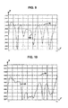
- the figure 9 illustrates a curve 110 of the loss P of reflection radiation ("return loss" in English), in dB, as a function of the frequency F in GHZ of the wave incident on the radome over a frequency range from 7.1 GHz at 8.5 GHz, for a parabolic antenna 1 meter in diameter with a radome having a single layer structure "sandwich" 3.7 mm thick already detailed above.
- the effectiveness of the known radome is limited. Indeed, the radome is not very transparent since the curve 110 has exceedances of the reference line 111, corresponding to the limit value of 18 dB, which occur at different points of the curve 110.
- this radome comprising a first layer 24 and a second layer 30 with a thickness of 3.7 mm, with a spacing between the first and second layers 24, 30 of 5 mm (similar to the radome of the figure 2 ), the performance over the frequency range 7.1 to 8.5 GHz is quite satisfactory, as illustrated in figure 10 (curve 112). A reflection loss of less than 18 dB is observed over the entire frequency band explored by curve 112.
Landscapes
- Details Of Aerials (AREA)
- Aerials With Secondary Devices (AREA)
Priority Applications (3)
| Application Number | Priority Date | Filing Date | Title |
|---|---|---|---|
| EP13305736.4A EP2811574B1 (de) | 2013-06-03 | 2013-06-03 | Starres Radom für eine Antenne mit Konkavreflektor |
| PCT/IB2014/061920 WO2014195869A2 (fr) | 2013-06-03 | 2014-06-03 | Radôme rigide pour une antenne a reflecteur concave |
| CN201480031960.2A CN105264713B (zh) | 2013-06-03 | 2014-06-03 | 用于带凹面反射器的天线的刚性天线罩 |
Applications Claiming Priority (1)
| Application Number | Priority Date | Filing Date | Title |
|---|---|---|---|
| EP13305736.4A EP2811574B1 (de) | 2013-06-03 | 2013-06-03 | Starres Radom für eine Antenne mit Konkavreflektor |
Publications (2)
| Publication Number | Publication Date |
|---|---|
| EP2811574A1 true EP2811574A1 (de) | 2014-12-10 |
| EP2811574B1 EP2811574B1 (de) | 2018-08-22 |
Family
ID=48670472
Family Applications (1)
| Application Number | Title | Priority Date | Filing Date |
|---|---|---|---|
| EP13305736.4A Active EP2811574B1 (de) | 2013-06-03 | 2013-06-03 | Starres Radom für eine Antenne mit Konkavreflektor |
Country Status (3)
| Country | Link |
|---|---|
| EP (1) | EP2811574B1 (de) |
| CN (1) | CN105264713B (de) |
| WO (1) | WO2014195869A2 (de) |
Cited By (1)
| Publication number | Priority date | Publication date | Assignee | Title |
|---|---|---|---|---|
| CN113140908A (zh) * | 2021-04-15 | 2021-07-20 | 大连海事大学 | 一种宽带圆极化卫星导航移动终端天线罩 |
Citations (4)
| Publication number | Priority date | Publication date | Assignee | Title |
|---|---|---|---|---|
| US20100103072A1 (en) * | 2008-10-24 | 2010-04-29 | Kuang-Yuh Wu | Honey Comb-Backed Armored Radome |
| US20110234468A1 (en) * | 2008-12-05 | 2011-09-29 | Norihiko Omuro | Antenna device and communication device provided therewith |
| US20110248902A1 (en) * | 2010-04-09 | 2011-10-13 | Tetsuya Miyagawa | Radome, antenna device and radar apparatus |
| US20120176294A1 (en) * | 2006-09-29 | 2012-07-12 | Kviatkofsky James F | Shaped ballistic radome |
Family Cites Families (2)
| Publication number | Priority date | Publication date | Assignee | Title |
|---|---|---|---|---|
| CN2653716Y (zh) * | 2003-08-18 | 2004-11-03 | 黎萍 | 一种吸顶式移动通讯天线 |
| CN101364669B (zh) * | 2008-09-25 | 2012-08-29 | 东华大学 | 超高分子量聚乙烯增强的雷达罩、其制备方法及应用 |
-
2013
- 2013-06-03 EP EP13305736.4A patent/EP2811574B1/de active Active
-
2014
- 2014-06-03 WO PCT/IB2014/061920 patent/WO2014195869A2/fr not_active Ceased
- 2014-06-03 CN CN201480031960.2A patent/CN105264713B/zh active Active
Patent Citations (4)
| Publication number | Priority date | Publication date | Assignee | Title |
|---|---|---|---|---|
| US20120176294A1 (en) * | 2006-09-29 | 2012-07-12 | Kviatkofsky James F | Shaped ballistic radome |
| US20100103072A1 (en) * | 2008-10-24 | 2010-04-29 | Kuang-Yuh Wu | Honey Comb-Backed Armored Radome |
| US20110234468A1 (en) * | 2008-12-05 | 2011-09-29 | Norihiko Omuro | Antenna device and communication device provided therewith |
| US20110248902A1 (en) * | 2010-04-09 | 2011-10-13 | Tetsuya Miyagawa | Radome, antenna device and radar apparatus |
Cited By (1)
| Publication number | Priority date | Publication date | Assignee | Title |
|---|---|---|---|---|
| CN113140908A (zh) * | 2021-04-15 | 2021-07-20 | 大连海事大学 | 一种宽带圆极化卫星导航移动终端天线罩 |
Also Published As
| Publication number | Publication date |
|---|---|
| CN105264713B (zh) | 2018-07-24 |
| CN105264713A (zh) | 2016-01-20 |
| WO2014195869A2 (fr) | 2014-12-11 |
| EP2811574B1 (de) | 2018-08-22 |
| WO2014195869A3 (fr) | 2015-06-25 |
Similar Documents
| Publication | Publication Date | Title |
|---|---|---|
| EP2573872B1 (de) | Linsenantenne, die eine dielektrische, beugende Komponente umfasst, die in der Lage ist, eine Hyperfrequenzwellenfront zu formen | |
| EP2804259B1 (de) | Radom für eine Antenne mit Konkavreflektor | |
| EP2081258B1 (de) | Subreflektor einer Doppelreflektorantenne | |
| FR2939970A1 (fr) | Radome pour antenne parabolique large bande. | |
| FR2986376A1 (fr) | Reflecteur secondaire d'antenne a double reflecteur | |
| FR3104835A1 (fr) | Antenne a onde de fuite en technologie afsiw | |
| WO2014044786A1 (fr) | Absorbant electromagnetique | |
| EP2658032B1 (de) | Hornstrahler einer Antenne mit gewelltem Gitter | |
| EP2811574B1 (de) | Starres Radom für eine Antenne mit Konkavreflektor | |
| EP2610966B1 (de) | Kompakte Breitbandantenne von sehr geringer Dicke und mit doppelten orthogonalen linearen Polarisierungen, die für den V/UHF-Bandbereich konzipiert ist | |
| FR2814614A1 (fr) | Lentille divergente a dome pour ondes hyperfrequences et antenne comportant une telle lentille | |
| EP2817850B1 (de) | Elektromagnetische bandlückenvorrichtung, verwendung davon in einer antennenvorrichtung und parameterfestlegungsverfahren für die antennenvorrichtung | |
| EP3903381B1 (de) | Verfahren zur integration einer »netzwerk -antenne in ein anderes elektromagnetisches medium und zugehörige antenne | |
| EP3325985B1 (de) | Vorrichtung für elektromagnetische dosimetrie und zugehöriges verfahren | |
| EP4148902A1 (de) | Elektromagnetisches system mit winkelabweichung der hauptkeule einer antenne | |
| FR2968848A1 (fr) | Antenne a reflecteur parabolique | |
| EP2772985A1 (de) | System zum Befestigen einer flachen Antennenkuppel auf einem Konkavreflektor einer Antenne | |
| FR2671235A1 (fr) | Antenne offset avec radome. | |
| FR3135170A1 (fr) | Antenne cornet améliorée | |
| FR3154872A1 (fr) | Dispositif d'émission / réception à domaine de dépointage étendu | |
| WO2008065148A2 (fr) | Dispositif d'alimentation d'une antenne à réflecteur | |
| FR3151945A1 (fr) | Antenne à réseau transmetteur | |
| FR3109027A1 (fr) | Absorbant radar large bande ajustable | |
| FR2713829A1 (fr) | Procédé de fabrication d'un radome autoportant. |
Legal Events
| Date | Code | Title | Description |
|---|---|---|---|
| PUAI | Public reference made under article 153(3) epc to a published international application that has entered the european phase |
Free format text: ORIGINAL CODE: 0009012 |
|
| 17P | Request for examination filed |
Effective date: 20130603 |
|
| AK | Designated contracting states |
Kind code of ref document: A1 Designated state(s): AL AT BE BG CH CY CZ DE DK EE ES FI FR GB GR HR HU IE IS IT LI LT LU LV MC MK MT NL NO PL PT RO RS SE SI SK SM TR |
|
| AX | Request for extension of the european patent |
Extension state: BA ME |
|
| R17P | Request for examination filed (corrected) |
Effective date: 20150610 |
|
| RBV | Designated contracting states (corrected) |
Designated state(s): AL AT BE BG CH CY CZ DE DK EE ES FI FR GB GR HR HU IE IS IT LI LT LU LV MC MK MT NL NO PL PT RO RS SE SI SK SM TR |
|
| GRAP | Despatch of communication of intention to grant a patent |
Free format text: ORIGINAL CODE: EPIDOSNIGR1 |
|
| STAA | Information on the status of an ep patent application or granted ep patent |
Free format text: STATUS: GRANT OF PATENT IS INTENDED |
|
| GRAJ | Information related to disapproval of communication of intention to grant by the applicant or resumption of examination proceedings by the epo deleted |
Free format text: ORIGINAL CODE: EPIDOSDIGR1 |
|
| STAA | Information on the status of an ep patent application or granted ep patent |
Free format text: STATUS: REQUEST FOR EXAMINATION WAS MADE |
|
| INTG | Intention to grant announced |
Effective date: 20171116 |
|
| INTC | Intention to grant announced (deleted) | ||
| GRAJ | Information related to disapproval of communication of intention to grant by the applicant or resumption of examination proceedings by the epo deleted |
Free format text: ORIGINAL CODE: EPIDOSDIGR1 |
|
| GRAP | Despatch of communication of intention to grant a patent |
Free format text: ORIGINAL CODE: EPIDOSNIGR1 |
|
| STAA | Information on the status of an ep patent application or granted ep patent |
Free format text: STATUS: GRANT OF PATENT IS INTENDED |
|
| INTC | Intention to grant announced (deleted) | ||
| INTG | Intention to grant announced |
Effective date: 20180219 |
|
| GRAS | Grant fee paid |
Free format text: ORIGINAL CODE: EPIDOSNIGR3 |
|
| GRAJ | Information related to disapproval of communication of intention to grant by the applicant or resumption of examination proceedings by the epo deleted |
Free format text: ORIGINAL CODE: EPIDOSDIGR1 |
|
| GRAL | Information related to payment of fee for publishing/printing deleted |
Free format text: ORIGINAL CODE: EPIDOSDIGR3 |
|
| STAA | Information on the status of an ep patent application or granted ep patent |
Free format text: STATUS: REQUEST FOR EXAMINATION WAS MADE |
|
| GRAR | Information related to intention to grant a patent recorded |
Free format text: ORIGINAL CODE: EPIDOSNIGR71 |
|
| STAA | Information on the status of an ep patent application or granted ep patent |
Free format text: STATUS: GRANT OF PATENT IS INTENDED |
|
| GRAA | (expected) grant |
Free format text: ORIGINAL CODE: 0009210 |
|
| STAA | Information on the status of an ep patent application or granted ep patent |
Free format text: STATUS: THE PATENT HAS BEEN GRANTED |
|
| INTC | Intention to grant announced (deleted) | ||
| INTG | Intention to grant announced |
Effective date: 20180712 |
|
| AK | Designated contracting states |
Kind code of ref document: B1 Designated state(s): AL AT BE BG CH CY CZ DE DK EE ES FI FR GB GR HR HU IE IS IT LI LT LU LV MC MK MT NL NO PL PT RO RS SE SI SK SM TR |
|
| REG | Reference to a national code |
Ref country code: GB Ref legal event code: FG4D Free format text: NOT ENGLISH |
|
| REG | Reference to a national code |
Ref country code: CH Ref legal event code: EP |
|
| REG | Reference to a national code |
Ref country code: AT Ref legal event code: REF Ref document number: 1033533 Country of ref document: AT Kind code of ref document: T Effective date: 20180915 |
|
| REG | Reference to a national code |
Ref country code: IE Ref legal event code: FG4D Free format text: LANGUAGE OF EP DOCUMENT: FRENCH |
|
| REG | Reference to a national code |
Ref country code: DE Ref legal event code: R096 Ref document number: 602013042323 Country of ref document: DE |
|
| REG | Reference to a national code |
Ref country code: NL Ref legal event code: MP Effective date: 20180822 |
|
| REG | Reference to a national code |
Ref country code: LT Ref legal event code: MG4D |
|
| PG25 | Lapsed in a contracting state [announced via postgrant information from national office to epo] |
Ref country code: FI Free format text: LAPSE BECAUSE OF FAILURE TO SUBMIT A TRANSLATION OF THE DESCRIPTION OR TO PAY THE FEE WITHIN THE PRESCRIBED TIME-LIMIT Effective date: 20180822 Ref country code: BG Free format text: LAPSE BECAUSE OF FAILURE TO SUBMIT A TRANSLATION OF THE DESCRIPTION OR TO PAY THE FEE WITHIN THE PRESCRIBED TIME-LIMIT Effective date: 20181122 Ref country code: NL Free format text: LAPSE BECAUSE OF FAILURE TO SUBMIT A TRANSLATION OF THE DESCRIPTION OR TO PAY THE FEE WITHIN THE PRESCRIBED TIME-LIMIT Effective date: 20180822 Ref country code: LT Free format text: LAPSE BECAUSE OF FAILURE TO SUBMIT A TRANSLATION OF THE DESCRIPTION OR TO PAY THE FEE WITHIN THE PRESCRIBED TIME-LIMIT Effective date: 20180822 Ref country code: NO Free format text: LAPSE BECAUSE OF FAILURE TO SUBMIT A TRANSLATION OF THE DESCRIPTION OR TO PAY THE FEE WITHIN THE PRESCRIBED TIME-LIMIT Effective date: 20181122 Ref country code: SE Free format text: LAPSE BECAUSE OF FAILURE TO SUBMIT A TRANSLATION OF THE DESCRIPTION OR TO PAY THE FEE WITHIN THE PRESCRIBED TIME-LIMIT Effective date: 20180822 Ref country code: IS Free format text: LAPSE BECAUSE OF FAILURE TO SUBMIT A TRANSLATION OF THE DESCRIPTION OR TO PAY THE FEE WITHIN THE PRESCRIBED TIME-LIMIT Effective date: 20181222 Ref country code: GR Free format text: LAPSE BECAUSE OF FAILURE TO SUBMIT A TRANSLATION OF THE DESCRIPTION OR TO PAY THE FEE WITHIN THE PRESCRIBED TIME-LIMIT Effective date: 20181123 Ref country code: RS Free format text: LAPSE BECAUSE OF FAILURE TO SUBMIT A TRANSLATION OF THE DESCRIPTION OR TO PAY THE FEE WITHIN THE PRESCRIBED TIME-LIMIT Effective date: 20180822 |
|
| REG | Reference to a national code |
Ref country code: AT Ref legal event code: MK05 Ref document number: 1033533 Country of ref document: AT Kind code of ref document: T Effective date: 20180822 |
|
| PG25 | Lapsed in a contracting state [announced via postgrant information from national office to epo] |
Ref country code: AL Free format text: LAPSE BECAUSE OF FAILURE TO SUBMIT A TRANSLATION OF THE DESCRIPTION OR TO PAY THE FEE WITHIN THE PRESCRIBED TIME-LIMIT Effective date: 20180822 Ref country code: HR Free format text: LAPSE BECAUSE OF FAILURE TO SUBMIT A TRANSLATION OF THE DESCRIPTION OR TO PAY THE FEE WITHIN THE PRESCRIBED TIME-LIMIT Effective date: 20180822 Ref country code: LV Free format text: LAPSE BECAUSE OF FAILURE TO SUBMIT A TRANSLATION OF THE DESCRIPTION OR TO PAY THE FEE WITHIN THE PRESCRIBED TIME-LIMIT Effective date: 20180822 |
|
| PG25 | Lapsed in a contracting state [announced via postgrant information from national office to epo] |
Ref country code: CZ Free format text: LAPSE BECAUSE OF FAILURE TO SUBMIT A TRANSLATION OF THE DESCRIPTION OR TO PAY THE FEE WITHIN THE PRESCRIBED TIME-LIMIT Effective date: 20180822 Ref country code: IT Free format text: LAPSE BECAUSE OF FAILURE TO SUBMIT A TRANSLATION OF THE DESCRIPTION OR TO PAY THE FEE WITHIN THE PRESCRIBED TIME-LIMIT Effective date: 20180822 Ref country code: AT Free format text: LAPSE BECAUSE OF FAILURE TO SUBMIT A TRANSLATION OF THE DESCRIPTION OR TO PAY THE FEE WITHIN THE PRESCRIBED TIME-LIMIT Effective date: 20180822 Ref country code: EE Free format text: LAPSE BECAUSE OF FAILURE TO SUBMIT A TRANSLATION OF THE DESCRIPTION OR TO PAY THE FEE WITHIN THE PRESCRIBED TIME-LIMIT Effective date: 20180822 Ref country code: PL Free format text: LAPSE BECAUSE OF FAILURE TO SUBMIT A TRANSLATION OF THE DESCRIPTION OR TO PAY THE FEE WITHIN THE PRESCRIBED TIME-LIMIT Effective date: 20180822 Ref country code: RO Free format text: LAPSE BECAUSE OF FAILURE TO SUBMIT A TRANSLATION OF THE DESCRIPTION OR TO PAY THE FEE WITHIN THE PRESCRIBED TIME-LIMIT Effective date: 20180822 Ref country code: ES Free format text: LAPSE BECAUSE OF FAILURE TO SUBMIT A TRANSLATION OF THE DESCRIPTION OR TO PAY THE FEE WITHIN THE PRESCRIBED TIME-LIMIT Effective date: 20180822 |
|
| REG | Reference to a national code |
Ref country code: DE Ref legal event code: R097 Ref document number: 602013042323 Country of ref document: DE |
|
| PG25 | Lapsed in a contracting state [announced via postgrant information from national office to epo] |
Ref country code: SK Free format text: LAPSE BECAUSE OF FAILURE TO SUBMIT A TRANSLATION OF THE DESCRIPTION OR TO PAY THE FEE WITHIN THE PRESCRIBED TIME-LIMIT Effective date: 20180822 Ref country code: SM Free format text: LAPSE BECAUSE OF FAILURE TO SUBMIT A TRANSLATION OF THE DESCRIPTION OR TO PAY THE FEE WITHIN THE PRESCRIBED TIME-LIMIT Effective date: 20180822 Ref country code: DK Free format text: LAPSE BECAUSE OF FAILURE TO SUBMIT A TRANSLATION OF THE DESCRIPTION OR TO PAY THE FEE WITHIN THE PRESCRIBED TIME-LIMIT Effective date: 20180822 |
|
| PLBE | No opposition filed within time limit |
Free format text: ORIGINAL CODE: 0009261 |
|
| STAA | Information on the status of an ep patent application or granted ep patent |
Free format text: STATUS: NO OPPOSITION FILED WITHIN TIME LIMIT |
|
| 26N | No opposition filed |
Effective date: 20190523 |
|
| PG25 | Lapsed in a contracting state [announced via postgrant information from national office to epo] |
Ref country code: SI Free format text: LAPSE BECAUSE OF FAILURE TO SUBMIT A TRANSLATION OF THE DESCRIPTION OR TO PAY THE FEE WITHIN THE PRESCRIBED TIME-LIMIT Effective date: 20180822 |
|
| PG25 | Lapsed in a contracting state [announced via postgrant information from national office to epo] |
Ref country code: MC Free format text: LAPSE BECAUSE OF FAILURE TO SUBMIT A TRANSLATION OF THE DESCRIPTION OR TO PAY THE FEE WITHIN THE PRESCRIBED TIME-LIMIT Effective date: 20180822 |
|
| REG | Reference to a national code |
Ref country code: CH Ref legal event code: PL |
|
| REG | Reference to a national code |
Ref country code: BE Ref legal event code: MM Effective date: 20190630 |
|
| PG25 | Lapsed in a contracting state [announced via postgrant information from national office to epo] |
Ref country code: TR Free format text: LAPSE BECAUSE OF FAILURE TO SUBMIT A TRANSLATION OF THE DESCRIPTION OR TO PAY THE FEE WITHIN THE PRESCRIBED TIME-LIMIT Effective date: 20180822 |
|
| PG25 | Lapsed in a contracting state [announced via postgrant information from national office to epo] |
Ref country code: IE Free format text: LAPSE BECAUSE OF NON-PAYMENT OF DUE FEES Effective date: 20190603 |
|
| PG25 | Lapsed in a contracting state [announced via postgrant information from national office to epo] |
Ref country code: CH Free format text: LAPSE BECAUSE OF NON-PAYMENT OF DUE FEES Effective date: 20190630 Ref country code: LU Free format text: LAPSE BECAUSE OF NON-PAYMENT OF DUE FEES Effective date: 20190603 Ref country code: BE Free format text: LAPSE BECAUSE OF NON-PAYMENT OF DUE FEES Effective date: 20190630 Ref country code: LI Free format text: LAPSE BECAUSE OF NON-PAYMENT OF DUE FEES Effective date: 20190630 |
|
| PG25 | Lapsed in a contracting state [announced via postgrant information from national office to epo] |
Ref country code: PT Free format text: LAPSE BECAUSE OF FAILURE TO SUBMIT A TRANSLATION OF THE DESCRIPTION OR TO PAY THE FEE WITHIN THE PRESCRIBED TIME-LIMIT Effective date: 20181222 |
|
| PG25 | Lapsed in a contracting state [announced via postgrant information from national office to epo] |
Ref country code: CY Free format text: LAPSE BECAUSE OF FAILURE TO SUBMIT A TRANSLATION OF THE DESCRIPTION OR TO PAY THE FEE WITHIN THE PRESCRIBED TIME-LIMIT Effective date: 20180822 |
|
| PG25 | Lapsed in a contracting state [announced via postgrant information from national office to epo] |
Ref country code: HU Free format text: LAPSE BECAUSE OF FAILURE TO SUBMIT A TRANSLATION OF THE DESCRIPTION OR TO PAY THE FEE WITHIN THE PRESCRIBED TIME-LIMIT; INVALID AB INITIO Effective date: 20130603 Ref country code: MT Free format text: LAPSE BECAUSE OF FAILURE TO SUBMIT A TRANSLATION OF THE DESCRIPTION OR TO PAY THE FEE WITHIN THE PRESCRIBED TIME-LIMIT Effective date: 20180822 |
|
| PG25 | Lapsed in a contracting state [announced via postgrant information from national office to epo] |
Ref country code: MK Free format text: LAPSE BECAUSE OF FAILURE TO SUBMIT A TRANSLATION OF THE DESCRIPTION OR TO PAY THE FEE WITHIN THE PRESCRIBED TIME-LIMIT Effective date: 20180822 |
|
| PGFP | Annual fee paid to national office [announced via postgrant information from national office to epo] |
Ref country code: DE Payment date: 20250429 Year of fee payment: 13 |
|
| PGFP | Annual fee paid to national office [announced via postgrant information from national office to epo] |
Ref country code: GB Payment date: 20250501 Year of fee payment: 13 |
|
| PGFP | Annual fee paid to national office [announced via postgrant information from national office to epo] |
Ref country code: FR Payment date: 20250508 Year of fee payment: 13 |
|
| REG | Reference to a national code |
Ref country code: DE Ref legal event code: R081 Ref document number: 602013042323 Country of ref document: DE Owner name: NOKIA SOLUTIONS (SHANGHAI) CO., LTD., CN Free format text: FORMER OWNER: ALCATEL-LUCENT SHANGHAI BELL CO., LTD., SHANGHAI, CN |